

Page 1
GE
T
Digital Energy
GT Series
Relay Card
1 SAFETY RULES
This manual contains all necessary information about the correct installation of the Relay Card into the
Digital Energy™ GT Series. Before attempting to install or operate the equipment, carefully read this manual. Keep
this manual together with the User manual next to the UPS for future references.
Full understanding of and compliance with the safety instructions and warnings contained in this manual are the
ONLY CONDITIONS
to avoid any dangerous situation during installation, operation and maintenance work, and to preserve the
maximum reliability of the UPS system.
NOTE !
The installation and cabling of the option “Relay Card” must be performed by a
QUALIFIED SERVICE PERSON*.
Please refer to the “Safety Rules” included in the “Operating Manual” of the UPS.
If any problems are encountered with the description of this installation guide, please contact the
nearest Service Centre before proceeding.
CAUTION !
These are sensitive electronic devices. Risk of electrostatic discharge!
Qualified, skilled personnel
are persons who (because of their training, experience, and position as well as their knowledge of appropriate standards,
regulations, health and safety requirements and working conditions) are authorised to be responsible for the safety of the
equipment, at all times whilst carrying out their normal duties and are therefore aware of, and can report, possible hazards
(observe IEC 60364 and national wiring regulations and accident prevention rules).
GE refuses any responsibility in case of non-observance, unauthorized alterations or improper use of the delivered UPS.
While every care has been taken to ensure the completeness and accuracy of this manual, GE accepts no responsibility or
liability for any loss or damage resulting from the use of the information contained in this document.
This document shall not be copied nor reproduced without the permission of GE.
Due to technical improvements, some of the information contained in this manual may be changed without notice.
2 INTRODUCTION
Description
Package contents:
he Relay Card is to be installed in the option slot of the
Digital Energy™ UPS GT Series model. The card is provided
with a 9-pole sub-D connector and four potential free
changeover contacts, representing: battery low, bypass
active, mains failure and general alarm.
Modifications reserved 1 ISG_OPT_REL_CRD_XGB_V010.doc
• ESD-proof bag with Relay Card
• This manual
Page 2
3 INSTALLATION
Be sure that you have read and fully understood Chapter 1 “Safety Rules”.
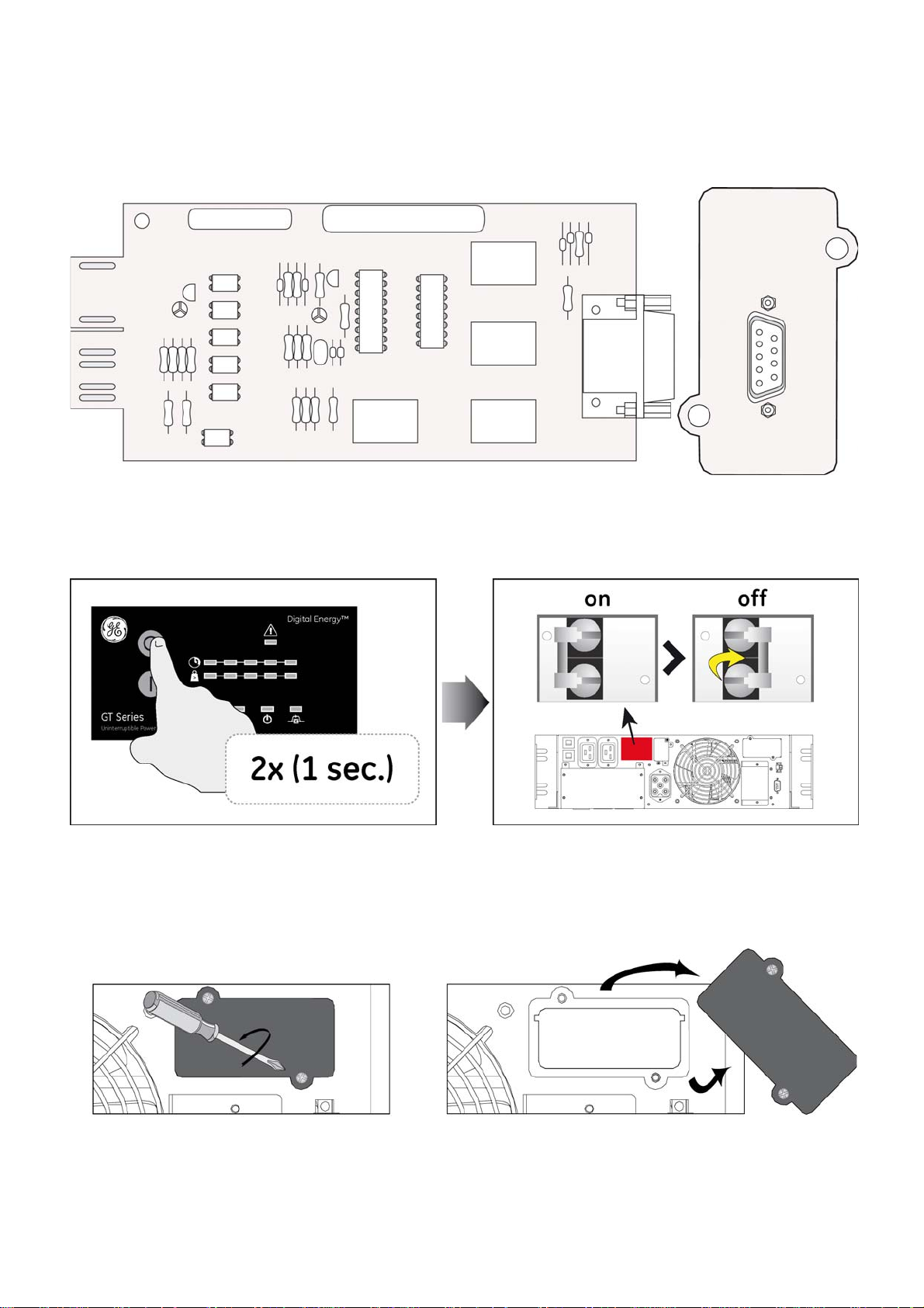
Fig. 1
• Fig 1: Top view of the Relay Card.
Fig. 2
• Fig 2: Press keypad “0” 2 times for 1 second to switch off the UPS. And turn the UPS input switch to
position “Off”.
Fig. 3
• Fig 3: Loosen cover of option slot, remove cover (save the screws for later use).
For the location of the option slot please consult the user manual of the UPS.
Modifications reserved 2 ISG_OPT_REL_CRD_XGB_V010.doc
Page 3

• Fig 4: Insert the relay card into the option slot.
Slide the card on the guides on the sides of the slot. Do not attempt to install upside-down – keeping
the screw holes aligned will ensure the correct installation. Secure the card using the screws
removed in the previous step.
Fig. 4
Fig. 5 Fig. 6
• Fig 5: Sub D-9 Pin configuration
When the Shutdown pin is driven high (connected to 12V) it activates the UPS Shutdown signal. The
Shutdown signal is only effective during a mains failure, when the UPS is operating on Battery. The
UPS will shutdown two minutes after the signal activation.
• Fig 6: Connect data cable
Fig. 4
• Fig 7: Switch on the UPS
Modifications reserved 3 ISG_OPT_REL_CRD_XGB_V010.doc
Page 4

4 SPECIFICATIONS
12V Power Supply : 8-20V
12V Max. power :
Relay contacts :
Relay contacts rating :
Current 0.5A max (50VA or 30W max)
Shutdown :
Operating temp. :
Storage temp. :
0.6W
Sub D-9 connector, galvanic isolated
60VDC or 30VAC max
Connect to GND or 12V Power supply pin only
0 ~ +40°C
max. 60°C
*NOTICE!
Although the Relay Card output contacts are voltage free, they should not be connected to any mains
connected circuit. The outputs are not designed to switch AC loads directly. The shutdown input has been
designed to be driven by dry contact outputs only.
Do not attempt to power external devices using the 12V signal (pin 9)
Use reinforced isolation to the mains for equipment and cables connected to these connections.
GE Consumer & Industrial SA
General Electric Company
GE imagination at work
CH – 6595 Riazzino (Locarno)
Switzerland
T +41 (0)91 / 850 51 51
F +41 (0)91 / 850 51 44
www.gedigitalenergy.com
Modifications reserved 4 ISG_OPT_REL_CRD_XGB_V010.doc
 Loading...