

Page 1
GE
Industrial Solutions
ASTAT-XT® Soft Starters
Remote keypad installation
8 Amp to 72 Amp units (QT#0008 to QT#0072)
Product Number: QTAKPADKIT1
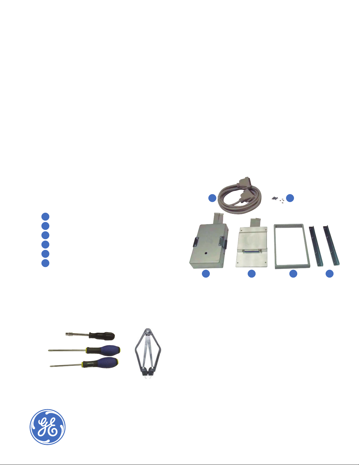
1. Kit components
A.
3 meters cable with connectors
B.
Remote keypad box
C.
Soft starter dummy cover
D.
Remote keypad frame
E.
Remote keypad PCB holding brackets
F.
Screws M3x8 (8 pieces) and nuts M3 (4 pieces)
2. Recommended tools
— Philips screw driver 2x125 mm
— Philips screw driver 1x100 mm
— 5.5 mm socket for M3 nut with a drive
— Flat cable connector extractor
A.
B. C. D. E.
F.
imagination at work
Page 2
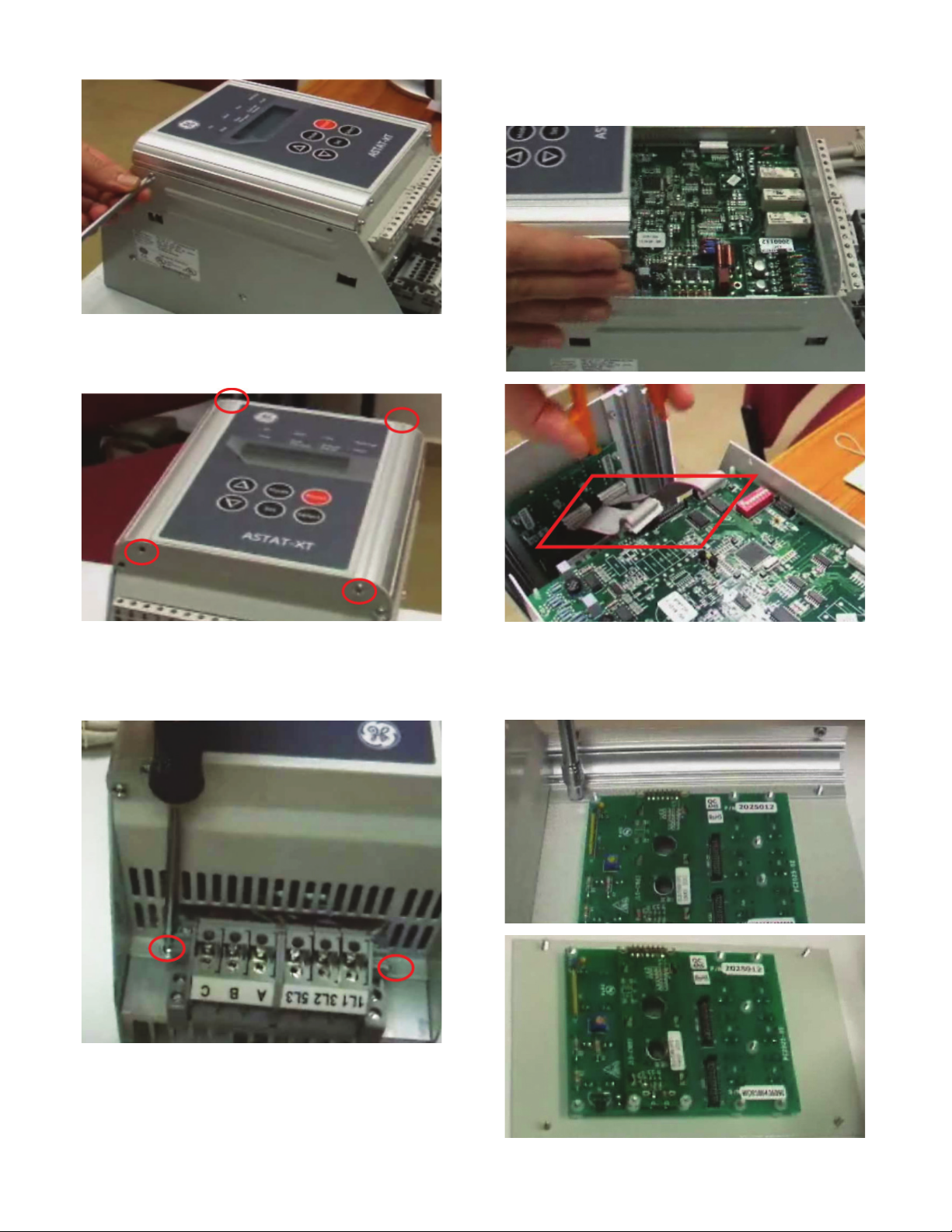
3. Remove 4 screws from side walls of the starter.
6. Remove the front cover and disconnect fl at
cable connections from main SMDP2000 and
from keypad PCB2025.
4. Remove 4 screws from the starter bottom wall.
5. Remove 2 screws holding the cover to the
heat sink.
7. Dismantle 4 nuts holding front cover to soft
starter frame.
Page 3
8. Mount the dummy cover (Item C) to soft starter
frame and fasten with 4 nuts.
Connect 2 fl at cable connectors to SMDP2000
9.
and install front cover back to place.
10. Fasten 2 screws that were loosened in Step 5.
11. Fasten 4 screws that were loosened in Step 3.
Do not fully fasten the screws.
12. Fasten 4 screws that were loosened in Step 4.
Install spring washers on the bottom screws.
13. Fully fasten 4 screws that were fastened in
Step 11.
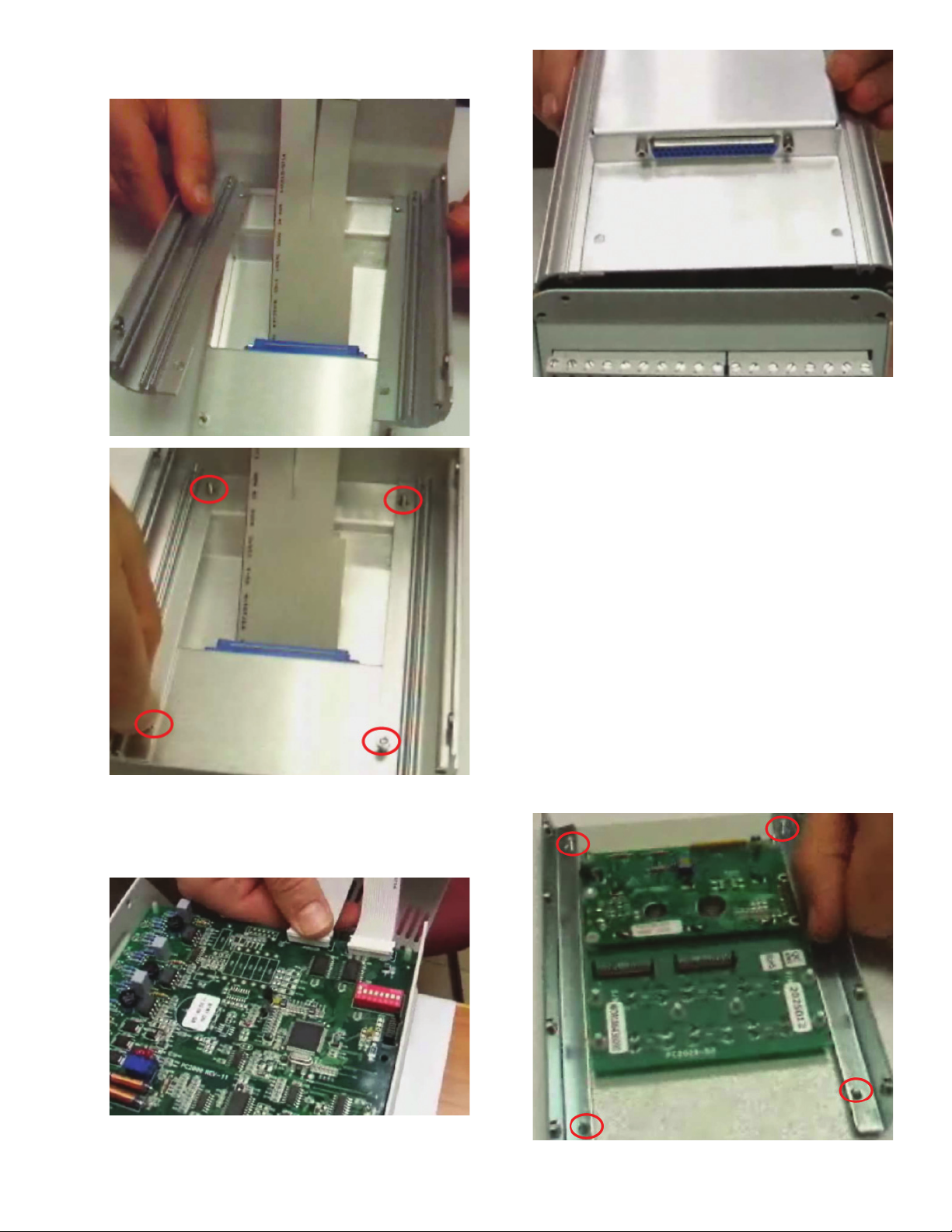
14. Put display unit in the holding brackets (Item E)
and fasten it with 4 nuts.
Page 4

15. Put the front display unit with brackets in the
remote keypad frame and fasten holding nuts.
16. Put and fully fasten 4 screws.
18.
Fasten 4 screws holding keypad unit to the box.
17. Connect 2 fl at cable connectors from remote
keypad box (Item B) to display unit.
19. Install the power module and remote keypad
and connect the cable. Connect cable (Item A)
between control module and power module.
imagination at work
DET-792 (03/13)
 Loading...