

Page 1
DEH40380 R02
g
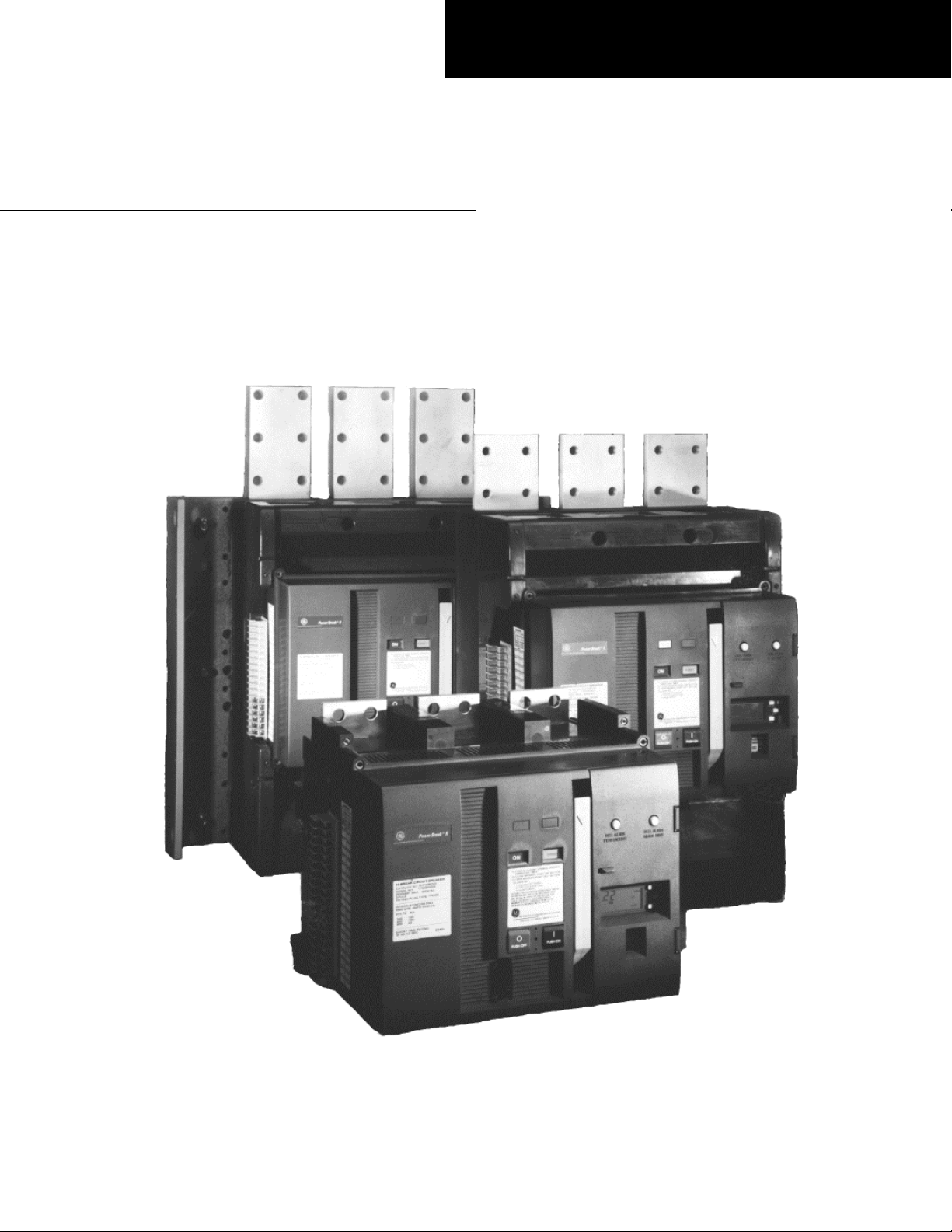
Power Break® II Switches
800–4000 A Frames, 240–600 Vac
User’s Guide
Page 2
Power Break® II Switches
Getting Started
Since this switch is available in a variety of configurations, please take a moment to compare the catalog number of your
purchased switch with the catalog number key below. Installation of an incorrect switch could result in misapplication,
lack of system coordination, or reduced system selectivity. If you have any questions, call the GE Customer Support
Center at 800-843-3742.
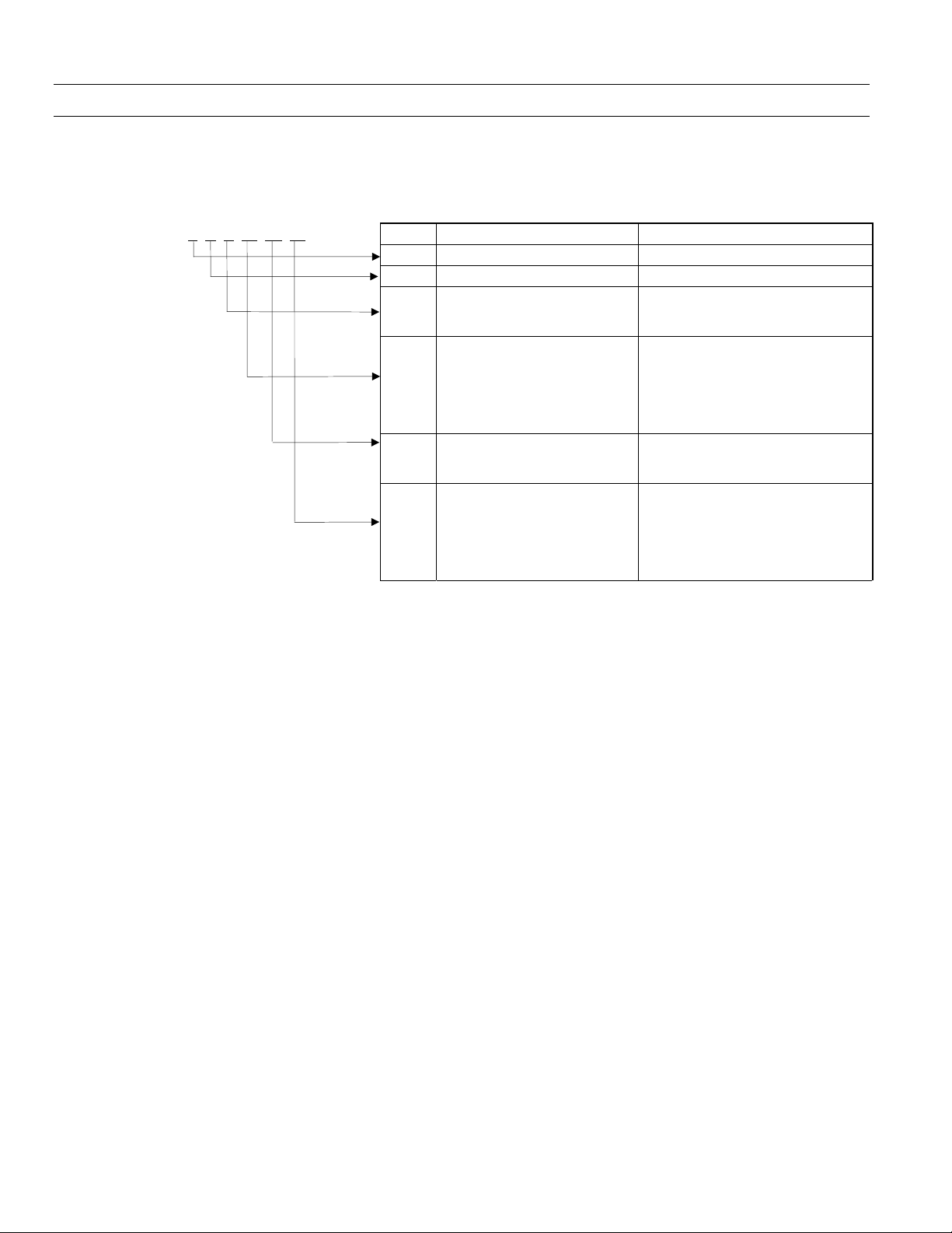
S H D 20 Y2 20 Code Description Function
H Hi-Break
B
08
Y2
08
Power Break® II insulated-case switch catalog numbering system.
S Power Break® II Switch Family
Frame Type
Back-connected
D
Draw-out
F
Front-connected
800 A
16
1600 A
20
2000 A
25
2500 A
30
3000 A
40
4000 A
up to 2000 A CTs
Y3
2500–3000 A CTs
Y4
4000 A CTs
800 A
16
1600 A
20
2000 A
25
2500 A
30
3000 A
40
4000 A
Connection Type
Frame Rating
Power+™ Control Unit
Maximum CT Current Rating
Example – a switch with catalog number SSD20Y220 has the following features:
• Power Break® II (S)
• Hi-Break frame (H)
• Draw-out (D)
• 2000 A frame rating (20)
• Control Unit with 2000 A CT (Y2)
• 2000 A CT rating (20)
Page 3

WARNINGS
CAUTIONS
NOTES
DEH40380
WARNINGS, CAUTIONS, AND NOTES
AS USED IN THIS PUBLICATION
Warning notices are used in this publication to emphasize that hazardous voltages, currents, or
other conditions that could cause personal injury are present in this equipment or may be
associated with its use.
Warning notices are also used for situations in which inattention or lack of equipment knowledge
could cause either personal injury or damage to equipment.
Caution notices are used for situations in which equipment might be damaged if care is not taken.
Notes call attention to information that is especially significant to understanding and operating the
equipment.
This document is based on information available at the time of its publication. While efforts have
been made to ensure accuracy, the information contained herein does not cover all details or
variations in hardware and software, nor does it provide for every possible contingency in
connection with installation, operation, and maintenance. Features may be described herein that
are not present in all hardware and software systems. GE Industrial Systems assumes no obligation
of notice to holders of this document with respect to changes subsequently made.
GE Industrial Systems makes no representation or warranty, expressed, implied, or statutory, with
respect to, and assumes no responsibility for the accuracy, completeness, sufficiency, or usefulness
of the information contained herein. No warrantees of merchantability or fitness for purpose shall
apply.
The following are trademarks of GE Company:
Power Break®, Power+™
© Copyright 2001 GE Company
All Rights Reserved
i
Page 4

Power Break® II Switches
Table of Contents
Chapter 1. Introduction
1-1 Overview ..................................................................................................................................... 1
1-2 Receiving the Switch .................................................................................................................. 1
Storage................................................................................................................................ 1
1-3 Preparation for Installation........................................................................................................ 1
Bolted Electrical Connections............................................................................................ 1
Panel Cutouts and Clearances............................................................................................ 1
Accessory Installation ......................................................................................................... 2
1-4 Switch Installation...................................................................................................................... 3
Chapter 2. Operation
2-1 Standard Features....................................................................................................................... 4
2-2 Operating Instructions............................................................................................................... 4
Sequence of Operations...................................................................................................... 4
Operating Instructions for Manually Operated Switchs..................................................... 4
Additional Instructions for Motor-Operated Switchs......................................................... 6
Padlock Operation.............................................................................................................. 6
Periodic Operational Checks.............................................................................................. 6
Wiring Notes ....................................................................................................................... 6
2-3 Trip Unit Setup .......................................................................................................................... 7
Chapter 3. Accessory Operation
3-1 Lug and Adapter Kits ................................................................................................................. 8
Lug Kits (800–2000 A Frames)........................................................................................... 8
Lug Kits with Straps (2500–4000 A Frames) ...................................................................... 8
T-Studs................................................................................................................................ 8
Adapter Kits ........................................................................................................................ 8
3-2 Plug-In Accessory Compartment................................................................................................ 9
3-3 Bell Alarm–Alarm Only.............................................................................................................. 9
Operation ........................................................................................................................... 9
3-4 Bell Alarm with Lockout............................................................................................................. 9
Operation ......................................................................................................................... 10
3-5 Shunt Trip................................................................................................................................ 10
Operation ......................................................................................................................... 10
3–6 Shunt Trip with Lockout......................................................................................................... 11
Operation ......................................................................................................................... 11
3-6 Undervoltage Release............................................................................................................... 11
Operation ......................................................................................................................... 11
3-8 Motor Operator Mechanism .................................................................................................... 12
Remote Operation............................................................................................................ 12
Automatic Operation........................................................................................................ 12
3-9 Remote Close............................................................................................................................ 12
Remote Operation............................................................................................................ 12
ii
Page 5

Power Break® II Switches
Table of Contents
3-10 Key Interlock Mounting Provision..........................................................................................13
Operation.......................................................................................................................... 13
3-11 Mechanical Counter ............................................................................................................... 14
3-12 Auxiliary Switch Module......................................................................................................... 14
Operation.......................................................................................................................... 14
3-13 Door Interlock.........................................................................................................................15
Operation.......................................................................................................................... 15
3-14 Push Button Cover.................................................................................................................. 15
Operation.......................................................................................................................... 15
Chapter 4. Trouble-Shooting Guide
............................................................................................ 17
iii
Page 6

Power Break® II Switches
List of Figures
1. Locations of the front-panel escutcheon cutout and mounting holes, 800–2000 A frames. .................. 2
2. Locations of the front-panel escutcheon cutout and monting plate, 2500–4000 A frames....................2
1
3. Locations of the
2000 A frames.......................................................................................................................................... 3
4. Locations of the
2500–3000 A back-connected frames. ..................................................................................................... 3
5. Locations of the 3/4-inch diameter through holes for mounting the switch in equipment, 4000 A
front-connected frame. ........................................................................................................................... 3
6. Front of the switch, showing the locations of standard features.............................................................4
7. Front of the switch, with the Trip Unit and top cover removed............................................................. 4
8. Side view of the switch, showing the padlock hasp extended.................................................................6
9. Terminal block mounted on the right side of the switch.......................................................................7
10. Locations of the plug-in accessory modules In the compartment on the front of the switch................ 9
11. Bell Alarm–Alarm Only module............................................................................................................. 9
12. Bell Alarm–Alarm Only connections on the right terminal block. ........................................................9
13. Bell Alarm with Lockout module..........................................................................................................10
14. Bell Alarm with Lockout connections on the right terminal block. ..................................................... 10
15. Shunt Trip module............................................................................................................................... 10
16. Shunt Trip with Lockout module......................................................................................................... 11
17. Undervoltage Release module. .............................................................................................................11
18. Motor Operator Mechanism.................................................................................................................12
19. Remote Close accessory......................................................................................................................... 13
20. Side view of the switch, showing the padlock tab extended with the Key Interlock installed. ............. 13
21. Mechanical Counter. ............................................................................................................................ 14
22. Auxiliary Switch Module with 12 switches. ...........................................................................................14
23. Auxiliary switch wiring diagram. ..........................................................................................................14
24. Door Interlock accessory installed on the switch.................................................................................. 15
25. Push Button Cover. ............................................................................................................................... 16
/4
–20 x 3/8-inch deep screw inserts for mounting the switch in equipment, 800–
3
/8–16 x 7/16-inch deep screw inserts for mounting the switch in equipment,
iv
Page 7

Power Break® II Switches
List of Tables
1. Weights of the various switch frame sizes, with and without a motor operator......................................1
2. Bolt sizes and mounting torques for bus connections.............................................................................1
3. Sequence of operations that may be performed with Power Break II circuit switches............................5
4. Accessory connections to the right terminal block B. .............................................................................7
5. Catalog numbers and wire sizes of Lug Kits for 800–2000 A frames. ......................................................8
6. Catalog numbers and specifications of Lug Kits with Straps for 2500–4000 A frames. ..........................8
7. Catalog numbers and ratings of T-Studs.................................................................................................8
8. Catalog numbers and ratings of Adapter Kits.........................................................................................8
9. Bell Alarm–Alarm Only catalog numbers...............................................................................................9
10. Bell Alarm with Lockout catalog numbers............................................................................................10
11. Catalog numbers and voltages for the Shunt Trip................................................................................10
12. Catalog numbers and voltages for the Shunt Trip with Lockout..........................................................11
13. Catalog numbers and voltages for the Undervoltage Release...............................................................12
14. Catalog numbers and operating voltages for the Motor Operator Mechanism. ..................................12
15. Catalog numbers and operating voltages for the Remote Close accessory...........................................13
16. Catalog numbers of Key Interlock models. ...........................................................................................13
17. Auxiliary Switch Module catalog numbers............................................................................................14
18. Auxiliary switch positions on the terminal board on the left side of the switch, Block A.....................15
v
Page 8

Page 9

Power Break® II Switches
Chapter 1. Introduction
1-1 Overview
Power Break® II insulated-case switches are designed to
serve low-voltage power circuits and equipment. They are
available with and Power+™ Control Units for operation
of accessories and optional ground-fault detection.
1-2 Receiving the Switch
Unpack the switch and inspect it for shipping damage.
Ensure that the switch has the proper current, voltage,
and interruption ratings for the application by comparing
the catalog number with the table in the Getting Started
section on the inside front page.
The weights of the various frame sizes are listed in Table
1, for reference.
Frame Rating Operation
800 A
1600 A or 2000
A
2500 A
Front Connect
2500 A
Back Connect
3000 A
Front Connect
3000 A
Back Connect
4000 A
Type
Manual
Electrical
Manual
Electrical
Manual
Electrical
Manual
Electrical
Manual
Electrical
Manual
Electrical
Manual
Electrical
Table 1. Weights of the various switch frame sizes, with and
without a motor operator.
Storage
The switch should be placed in service immediately in its
permanent location. However, if it must be stored for an
indefinite period, it should be carefully protected against
condensation, preferably by storage in a warm dry room.
Switches for outdoor equipment should be stored in that
equipment only when power is available and heaters are in
operation, to prevent condensation.
The switch should be stored in a clean location, free from
corrosive gases or fumes. In particular, protect the switch
from moisture and cement dust, as that combination may
be corrosive.
If the switch is stored for any length of time, it should be
inspected periodically to ensure good mechanical
condition.
Weight
(lb)
71
80
79
88
178
187
167
176
179
188
216
225
320
329
1-3 Preparation for Installation
Bolted Electrical Connections
Using an industry-accepted solvent, remove any foreign
material from the line and load strap surfaces and the
corresponding surfaces of the connecting bus. Ensure that
the mating surfaces are smooth and free of burrs and
nicks.
Place the bus connections in position and align the
mounting holes. Insert and fasten the mounting bolts and
washers according to specifications in Table 2.
Bus Connection
Switch Frame Bolt Diam. Torque
800A (1)
1600-2000A (2) 1/2 in. 300
2500 A (4) 3/8 in. 225
3000 A (4) 3/8 in. 225
4000 A (6) 1/2 in. 300
1
/2 in. 300
Table 2. Bolt sizes and mounting torques for bus connections.
Panel Cutouts and Clearances
Use the following information to prepare the equipment
and assure proper clearances for installation and
operation of the switch.
Figures 1 and 2 show the front-panel escutcheon cutout
patterns and the locations of the switch mounting bolts.
The standard door cutout dimensions require a trim plate
on the switch. The optional dimensions are for flush front
or nonhinged door construction and the trim plate may
be omitted. Ventilation cutouts are required for stationarymounted switches rated 1600 A and larger and for drawout switches rated 2000 A and larger. Ventilation cutouts
not
are
frame switches or for stationary-mounted 800 A frame
switches.
Because of arc chamber venting, the minimum throughair distance from the top of the switch’s molded case to
grounded metal for 800–2000 A switches is 4.50 inches
[114 mm] in an area 5.31 inches x 16.00 inches [135 mm x
406 mm], centered over the vent screens. (Refer to outline
drawings 10054370, Sheets 1–5, for details.)
For 2500–4000 A switches, the minimum through-air
distance from the top of the switch’s molded case to
grounded metal is 8.00 inches [203 mm] in an area 9.00
inches x 16.00 inches [227 mm x 406 mm], over the vent
screens. (Refer to outline drawings 10055629, Sheets 1–7,
for details.)
required for draw-out-mounted 800 A or 1600 A
(in-lb)
1
Page 10

Power Break® II Switches
Chapter 1. Introduction
Figure 1. Locations of the front-panel escutcheon cutout and
mounting holes, 800–2000 A frames.
Accessory Installation
The following accessories may be installed in the switch.
Refer to Chapter 3 of this publication for catalog numbers
and to the instruction sheet supplied with each accessory
for installation instructions.
• Lugs and Adapters
• Motor Operator Mechanism
• Remote Close
• Undervoltage Release
• Shunt Trip
• Shunt Trip with Lockout
• Bell Alarm–Alarm Only
• Bell Alarm with Lockout
• Auxiliary Switch Module
• Mechanical Counter
• Key Interlock Mounting Provision
• Push Button Cover
• Door Interlock
• Mechanical Interlock
Figure 2. Locations of the front-panel escutcheon cutout and
mounting plate, 2500–4000 A frames.
2
Page 11

1-4 Switch Installation
Ensure that all accessory connections are secure. Line up
the bolt holes in the enclosure with the attachment points
on the switch, illustrated in Figures 3, 4 and 5, insert the
bolts and tighten. Use
between the line and load terminals to support the switch.
nonmagnetic
material in the area
Power Break® II Switches
Chapter 1. Introduction
1
Figure 3. Locations of the
for mounting the switch in equipment, 800–2000 A frames.
Figure 4. Locations of the
for mounting the switch in equipment, 2500–3000 A back-
/4–20 x 3/8-inch deep screw inserts
3
/8–16 x 7/16-inch deep screw inserts
connected frames.
3
Figure 5. Locations of the
mounting the switch in equipment, 4000 A front-connected
/4-inch diameter through holes for
frame.
3
Page 12

Power Break® II Switches
Chapter 2. Operation
2-1 Standard Features
Power Break II switches are equipped with the following
standard features. The letters are keyed to the switch
photographs in Figures 6 and 7.
A Indicator:
B Indicator:
C
ON button
D
OFF button
E Manual charging handle
F Integral 36-point terminal block (12 auxiliary
switches, A-B type), Block “A”
G Integral 36-point terminal block (all other con-
nections), Block “B”
H Sealable hinged cover
I Cover mounting screws (4)
K Control Unit interchangeable rating plug
L Test set connection port
M Standard padlock provision
N Dust-resistant ventilation slots
ON – Red
OFF – Green
CHARGED – Yellow
DISCHARGED – White
Figure 7. Front of the switch, with the Control unit and top
cover removed.
2-2 Operating Instructions
Sequence of Operations
The sequence of operations that may be performed on the
switch are listed in Table 3. Refer to Chapter 3 for
information about accessory operation.
Figure 6. Front of the switch, showing the locations of
standard features.
Operating Instructions for Manually
Operated Switch
Charging the Mechanism Springs
Pull the operating handle down about 90° (until it stops).
Repeat five more times to fully charge the springs.
will not close the switch contacts.
will show
springs are fully charged, the handle locks in the stored
position.
NOTE:
are fully charged and the handle is stored fully in.
NOTE:
isée à moins que les ressorts soient réarmés tout à fait, et
le levier est complètement remis à la position
d’emmagasinage.
CHARGED on a yellow background. When the
The switch cannot be closed unless the springs
La fermeture de l'interrupteurne peut être réal-
The charge indicator
This
4
Page 13

Power Break® II Switches
Chapter 2 – Operation
On/Off
Indicator
OFF DISCHARGED Open Discharged Mechanism may be charged
OFF CHARGED Open Charged Contacts may be closed
ON DISCHARGED Closed Discharged Mechanism may be recharged or
ON CHARGED Closed Charged Contacts may be opened
Charge
Indicator
Main Switch
Contacts
Condition of
Charging Springs
Next Permissible Operating Function
Contacts may be opened
Table 3. Sequence of operations that may be performed with Power Break II switches.
Closing the Switch
Close the switch contacts with either of the following
methods:
• Depress the ON button on the front of the switch.
• Energize the (optional) Remote Close accessory by
applying rated voltage to terminals 16 and 34 on
terminal block B.
CAUTION:
If the switch latch is held in the tripped
position by any of the following conditions and an
attempt is made to close the main switch contacts, the
mechanism will “crash” (the closing springs discharge
with no motion of the switch contact arms). The switch
has been designed and tested to withstand more than
100 crash operations, but repeated attempts to close a
locked-out switch will damage the switch mechanism.
CAUTION:
the switch latch is held in the tripped position by any of
the following conditions:
• The Bell Alarm with Lockout was not reset after a
ground fault lockout.
• The Undervoltage Release is not energized.
The main switch contacts cannot be closed if
• The Key interlock or padlock is in the locked OFF
condition.
• The draw-out interlock is engaged with the carriage
between the TEST and T CONNECTED positions.
• The walking beam interlock or mechanical interlock
is activated.
• The Shunt Trip with Lockout is energized.
These conditions must be corrected before the switch
can be closed.
ATTENTION:
Les contacts de l'interrupteur principal
peuvent être fermés où le loquet de l'interrupteur est
maintenu en position déclenchée à cause de toute des
conditions suivantes:
• Si la réarmeture du déclencheur n’est pas réalisée
après le verrouillage en position “ouvert” provenant
du courant de surcharge.
• Si le minimum de tension (UVR) n’est pas sous
tension.
• Le déclenchement shunt avec blocage est actionné.
Ces conditions doivent être corrigées avant l'interrupteur
peut être fermé.
ATTENTION:
position de déclenchement dans n’importe quelle des
conditions suivantes et que l’on tente de fermer les
contacts de l'interrupteur principal, le mécanisme subira
un “crash” (les ressorts de fermeture se détendent sans
que les bras des contacts du disjoncteur ne bougent).
L'interrupteur a été conçu et testé pour résister à plus de
100 opérations de type “crash,” cependant des tentatives
répétées ayant pour but de fermer un interrupteur
bloqué endommageront le mécanisme de l'interrupteur.
• Si le verrou de clé ou le cadenas est verrouillé en
position OFF.
• Si le chariot du verrou débrochable est localisé entre
les positions TEST et CONNECTED.
• L’enclenchement par support mobile ou
Si le cliquet de l'interrupteur est tenu en
enclenchement mécanique est activé.
5
Page 14

Power Break® II Switches
Chapter 2. Operation
Opening the Switch
Open the switch contacts with either of the following
methods:
• Depress the OFF button on the front of the switch.
• Energize the (optional) Shunt Trip or Shunt Trip
with Lockout accessory or de-energize the (optional)
Undervoltage Release accessory.
Additional Instructions for Motor-Operated
Switches
Charging the Mechanism Springs
The mechanism closing springs may also be charged by
the following method:
• Short terminals 17 and 35 on the right terminal
block, with a push button or similar device, for a
minimum of five seconds.
• If power is lost during the charge cycle, finish
charging the springs by cycling the charging handle
until the indicator shows
background. When the springs are fully charged, the
handle locks in the stored position.
Automatic Operation
Connect terminals 17 and 35 on the terminal block on the
right side of the switch with a jumper wire. The Motor
Operator will automatically recharge the switch closing
springs whenever the switch closes.
CAUTION:
ATTENTION:
fermeture automatique.
Do not wire switches for automatic close.
Ne pas câbler les interrupteurs pour la
Padlock Operation
The padlock prevents the switch from closing by holding
the trip latch in the tripped position. To install the
padlock, use the following procedure:
1. Trip the switch (press the OFF button).
2. Grasp the padlock tab (see Figure 6) and pull it out
until it is fully extended, as illustrated in Figure 8.
Note that if the switch contacts are closed, the
padlock tab will not extend.
3. Insert the padlock; the switch will not close.
As many as three
one time.
1
/4" to 3/8" padlocks may be attached at
CHARGED on a yellow
Figure 8. Side view of the switch, showing the padlock tab
extended.
Periodic Operational Checks
Approximately once a year, verify that the switch is
operating correctly by opening and closing the
mechanism.
Wiring Notes
Figure 9 illustrates the terminal block installed on the
right side of the switch. Table 4 lists the device connections to the terminal block. Each terminal point will
accept the following connections:
• Bare stripped wire – one #12 AWG or two #14 AWG.
• Ring or spade connectors – two per terminal.
The terminal screws should be tightened to 7–9 in-lb
torque.
The left terminal block is blank unless the optional
Auxiliary Switch Module accessory is ordered. See Table
16 for the device connections to the Auxiliary Switch
Module terminal block.
6
Page 15

Figure 9. Terminal block mounted on the right side of the
switch.
Terminal Terminal
18 Motor Operator + 36 Motor Operator –
17 Remote Charge 35 Remote Charge
16 Remote Close + 34 Remote Close –
15 Bell Alarm only Com 33 Charge Indicator
14 Bell Alarm only NO 32 Shunt Trip
13 Bell Alarm only NC 31 Shunt Trip
12 Lockout Common 30 Undervoltage Release
11 Lockout NO 29 Undervoltage Release
10 Lockout NC 28 Reserved
9 Reserved 27 Reserved
8 Reserved 26 Zone-Select Input –
7 commnet – 25 Zone-Select Input +
6 commnet + 24 Zone-Select Output –
5 C Phase Volts 23 Zone-Select Output +
4 B Phase Volts 22 Draw-Out Switch
3 A Phase volts 21 Draw-Out Switch
2 24 Vdc – 20 N Tap
1 24 Vdc + 19 N Common
Do not apply voltage; see wiring diagram.
Not a user connection.
Table 4. Accessory connections to the right-side terminal block
B.
Power Break® II Switches
Chapter 2. Operation
2-3 Control Unit Setup
See DEH–40381 for detailed instructions on setting up
Power+ Control Units.
7
Page 16

Power Break® II Switches
Chapter 3. Accessory Operation
Following are the operation procedures for each of the
available switch accessories. See the user guides supplied
with the accessories for installation and removal.
3-1 Lug and Adapter Kits
Lug Kits (800–2000 A Frames)
Direct-mounting lugs bolt directly to the line or load strap
of the switch. Order one Lug Kit per line or load pole. Lug
Kit catalog numbers and wire sizes are listed in Table 5.
Cat. No. Wires Wire Sizes Amps
TPLUG106
TPLUG206 2 #2–600 kcmil CU/AL 600
TPLUG308 3 300-750 kcmil CU/AL 800
TPLUG408 4 500–800 kcmil CU/AL 1600
1
2
Table 5. Catalog numbers and wire sizes of Lug Kits for 800–
Lug Kits with Straps (2500–4000 A Frames)
Lug Kits with Straps include copper straps that connect
directly to switch T-studs (must be ordered separately) to
provide proper phase clearances for mounting lugs. Order
one Lug Kit with Straps per line or load side. Catalog
numbers are listed in Table 6.
Cat. No.
TSLUG08 9 3 800
TSLUG12 12 4 2500 or 1200
TSLUG16 15 5 3/0-800 3000 1600
TSLUG20 18 6 kcmil 2000
TSLUG25 21 7 Cu/Al 2500
TSLUG30 27 9 3000 3000
TSLUG40 33 11 4000 4000
Table 6. Catalog numbers and specifications of Lug Kits with
Lugs
per Kit
Straps for 2500–4000 A frames.
#2–600 kcmil CU/AL
1/0–250 kcmil CU/AL
2000 A frames.
Max.
Wires
per Pole
Wire
Range
Frame
Size (A)
400
Max.
Amps
T-Studs
T-Studs bolt directly to the line or load terminals of the
switch. Order one T-Stud per line or load pole. T-Stud
catalog numbers and ratings are listed in Table 7.
Cat. No. Material Frame (A)
SP08FCA Al 800 800 Front
SP08FCC Cu 800 800 Front
SP20FCA Al 1600–2000 2000 Front
SP20FCC Cu 1600–2000 2000 Front
SPS20FCA Al 2500 2000 Front
SPS20BCA Al 2500 2000 Back
SPS25FCC Cu 2500 2500 Front
SPS25BCC Cu 2500 2500 Back
SPS30FCC Cu 3000 3000 Front
N/A
SPS40FCC Cu 4000 4000 Front
SPS40LFCC Cu 4000 4000 Front
Integral T-Studs are not removable on 3000 A back-connected switches.
Long studs may be used in place of or alternated with SPS40FCC if
desired.
Cu 3000 3000 Back
Max.
Amps
Switch
Connect
Table 7. Catalog numbers and ratings of T-Studs.
Adapter Kits
Adapter Kits bolt directly to the line or load terminals on
the rear of the switch. They provide proper phase-to-phase
clearances for mounting lugs or busbars. Order one
Adapter Kit per three-phase line or load side. Lugs must
be ordered separately. Adapter Kit catalog numbers and
ratings are listed in Table 8.
Cat. No. Frame (A)
TPLUGA08 800
TPLUGA16
TPLUGA20
Premounts in equipment, allowing cabling or bussing to be completed
before switch mounting.
3/0–800 kcmil Cu/Al wire range.
Anderson No. VCEL-075-12H1 or equivalent.
1600
1600–2000
Table 8. Catalog numbers and ratings of Adapter Kits.
Lug Odering Information
(Per Line or Load Side)
9 TPLUG108
or 9 Crimp Lugs
18 TPLUG108
or 18 Crimp Lugs
18 TPLUG108
or 18 Crimp Lugs
Lugs
Lugs
Lugs
8
Page 17

Power Break® II Switches
Chapter 3. Accessory Operation
3-2 Plug-In Accessory Compartment
Several of the accessories are installed in the accessory
compartment on the front of the switch. Figure 10
illustrates this compartment and the locations of each of
the plug-in accessory modules.
Figure 10. Locations of the plug-in accessory modules in the
compartment on the front of the switch.
3-3 Bell Alarm–Alarm Only
The Bell Alarm–Alarm Only module, shown in Figure 11,
provides a switch to remotely indicate that the switch has
tripped. It is reset either automatically when the switch is
reclosed or manually when the reset button on the front
of the Bell Alarm–Alarm Only module is pressed.
Catalog No. Contact Rating
SPBAA240 6 A at 240 Vac
0.25 A at 250 Vdc
0.50 A at 125 Vdc
SPBAA600 6 A at 600 Vac
0.25 A at 250 Vdc
0.50 A at 125 Vdc
600 V version is not UL listed.
Table 9. Bell Alarm–Alarm Only catalog numbers.
Operation
The Bell Alarm–Alarm Only provides normally open (NO)
and normally closed (NC) outputs available at the
terminal block on the right side of the switch, as
illustrated in Figure 12. The outputs change state
whenever a switch ground fault trip occurs. This trip can
be caused by a ground fault condition detected by the
Control Unit.
The Bell Alarm–Alarm Only accessory resets automatically,
returning the outputs to their normal configuration, when
the switch is reclosed. The Bell Alarm–Alarm Only can
also be reset manually, before the switch is reclosed, by
pressing the reset button on the front of the module.
Figure 11. Bell Alarm–Alarm Only module.
The Power+™ Control Unit activates the Bell Alarm–
Alarm Only for protection trips only.
The catalog numbers for the Bell Alarm–Alarm Only are
listed in Table 9. For installation instructions see GEH–
6275.
Figure 12. Bell Alarm–Alarm Only connections on the right
terminal block. The contacts are shown in the reset state.
3-4 Bell Alarm with Lockout
The Bell Alarm with Lockout module, shown in Figure 13,
prevents reclosing of the switch after a ground fault trip
until the Bell Alarm with Lockout is reset. It can only be
reset by pressing the button on the top of the module.
This module also provides a switch to remotely indicate
that the switch has tripped.
The Power+™ Control Unit activates the Bell Alarm with
Lockout for ground fault protection trips only.
The catalog numbers for the Bell Alarm with Lockout are
listed in Table 10. For installation instructions see GEH–
6278.
9
Page 18

Power Break® II Switches
Chapter 3. Accessory Operation
Figure 13. Bell Alarm with Lockout module.
3-5 Shunt Trip
The Shunt Trip module, shown in Figure 15, allows the
switch to be tripped electrically from a remote location.
Catalog No. Contact Rating
SPBAL240 6 A at 240 Vac
0.25 A at 250 Vdc
0.50 A at 125 Vdc
SPBAL600 6 A at 600 Vac
0.25 A at 250 Vdc
0.50 A at 125 Vdc
The 600 V version is not UL listed.
Table 10. Bell Alarm with Lockout catalog numbers.
Operation
The Bell Alarm with Lockout prevents reclosing of the
switch after a ground fault trip until the reset button on
the front of the module is pressed. This trip can be caused
by a ground fault condition detected by the Control Unit.
In addition, the Bell Alarm with Lockout provides
normally open (NO) and normally closed (NC) alarm
outputs available at the terminal block on the right side of
the switch, as illustrated in Figure 14. These outputs are
returned to their normal state when the Bell Alarm with
Lockout reset button is firmly pressed.
Figure 14. Bell Alarm with Lockout connections on the right
terminal block. The contacts are shown in the reset state.
Figure 15. Shunt Trip module.
If the switch is equipped with a Power+™ Control Unit, it
is configured so that only ground fault trips will activate a
Bell Alarm–Alarm Only or Bell Alarm with Lockout.
The catalog numbers for the Shunt Trip for various
voltage applications are listed in Table 11. For installation
instructions see GEH–6284 or GEH–6519.
Catalog
Number
SPST012 12 Vdc 3.0 200
SPST024
SPST048
SPST120
SPST208 208 Vac 1.5 50
SPST240
SPST480 480 Vac 0.375 21
SPST600 600 Vac 0.3 17
24–600 Vac devices are rated for 50/60 Hz.
Peak inrush current is present for 2–6 ms after activation. This number is
provided so that fuses and supplies can be chosen appropriately.
Ratings for 480 Vac and 600 Vac devices are at the input of the upstream
transformer, included with the accessory and specified in GEH–6519,
which powers the device. For voltage and current ratings at the switch
terminal block, see SPST120.
Voltage
Rating
24 Vac
24 Vdc
48 Vac
48 Vdc
120 Vac
125 Vdc
240 Vac
250 Vdc
Peak Inrush
Current, A
Nominal RMS
Current, mA
1.5 140
1.5 110
1.5 85
1.5 40
Table 11. Catalog numbers and voltages for the Shunt Trip.
Operation
Apply control voltage to terminals 31 and 32 of the
terminal strip on the right side of the switch to open the
switch. The Shunt Trip will cause the switch to open when
the control voltage is greater than 75% of the dc-rated
value or 55% of the ac-rated value.
10
Page 19

Power Break® II Switches
Chapter 3. Accessory Operation
3–6 Shunt Trip with Lockout
The Shunt Trip with Lockout module, shown in Figure
16, allows the switch to be opened electrically from a
remote location and prevents the switch from closing
while the accessory is energized.
Figure 16. Shunt Trip with Lockout module.
If the switch is equipped with a Power+™ Control Unit, it
is configured so that only ground fault trips will activate a
Bell Alarm–Alarm Only or Bell Alarm with Lockout.
The catalog numbers for the Shunt Trip for various
voltage applications are listed in Table 12. For installation
instructions see GEH–6284 or GEH–6519.
Catalog
Number
SPSTL012 12 Vdc 19 300
SPSTL024
SPSTL048
SPSTL120
SPSTL208 208 Vac 1.9 60
SPSTL240
SPSTL480 480 Vac 0.75 20
SPSTL600 600 Vac 0.60 16
24–600 Vac devices are rated for 50/60 Hz.
Peak inrush current is present for 2–6 ms after activation. This number is
provided so that fuses and supplies can be chosen appropriately.
Ratings for 480 Vac and 600 Vac devices are at the input of the upstream
transformer, included with the accessory and specified in GEH–6519,
which powers the device. For voltage and current ratings at the switch
terminal block, see SPSTL120.
Table 12. Catalog numbers and voltages for the Shun t Trip
Voltage
Rating
24 Vac
24 Vdc
48 Vac
48 Vdc
120 Vac
125 Vdc
240 Vac
250 Vdc
Peak Inrush
Current, A
15 300
7.5 200
3.0 80
1.5 45
with Lockout.
Nominal RMS
Current, mA
3-7 Undervoltage Release
The Undervoltage Release (UVR) module, shown in
Figure 17, opens the switch when the input control voltage
drops to 35–60% of its rated value and prevents an open
switch from closing until the input control voltage is
greater than 80% of the rated value.
If the switch is equipped with a Power+™ Control Unit, it
is configured so that only ground fault trips will activate a
Bell Alarm–Alarm Only or Bell Alarm with Lockout.
Figure 17. Undervoltage Release module.
The catalog numbers for the UVR for various voltage
applications are listed in Table 13. For installation
instructions see GEH-6285 or GEH–6520.
Operation
Apply control voltage to terminals 29 and 30 of the
terminal strip on the right side of the switch. When the
applied control voltage is above 80% of the UVR’s rated
value, the switch can be closed. When the voltage drops to
35–60% of the rated value, the UVR will open the switch.
Operation
Apply control voltages to terminals 31 and 32 of the
terminal strip on the right side of the switch to open the
switch. The Shunt Trip with Lockout will cause the switch
to open when the control voltage is greater than 75% of
the dc-rated value or 55% of the ac-rated value.
11
Page 20

Power Break® II Switches
Chapter 3. Accessory Operation
Catalog
Number
SPUV012DC 12 Vdc 19 300
SPUV024DC 24 Vdc 15 140
SPUV048DC 48 Vdc 7.5 70
SPUV125DC 125 Vdc 3 30
SPUV250DC 250 Vdc 1.5 15
SPUV024AC 24 Vac 15 370
SPUV048AC 48 Vac 7.5 210
SPUV120AC 120 Vac 3 80
SPUV208AC 208 Vac 1.9 60
SPUV240AC 240 Vac 1.5 45
SPUV480AC 480 Vac 0.75 20
SPUV600AC 600 Vac 0.60 16
24–600 Vac devices are rated for 50/60 Hz.
Peak inrush current is present for 2–6 ms after activation. This number is
provided so that fuses and supplies can be chosen appropriately.
Ratings for 480 Vac and 600 Vac devices are at the input of the upstream
transformer, included with the accessory and specified in GEH–6520,
which powers the device. For voltage and current ratings at the switch
terminal block, see SPUV120AC.
Voltage
Rating
Peak Inrush
Current, A
Nominal RMS
Current, mA
Table 13. Catalog numbers and voltages for the Undervoltage
Release.
3-8 Motor Operator Mechanism
The Motor Operator Mechanism, shown in Figure 18,
provides a means of remotely or automatically charging
the springs that close the switch. Table 14 lists the catalog
numbers for the available Motor Operator Mechanism
models. For installation instructions see GEH-6281.
Catalog No. Voltage Rating
SPE024 24 Vdc
SPE048 48 Vdc
SPE072 72 Vdc
SPE120 120 Vac
SPE125 125 Vdc
SPE240 240 Vac
Table 14. Catalog numbers and operating voltages for the
Motor Operator Mechanism.
Remote Operation
The switch closing springs can be charged remotely by
shorting terminals 17 and 35 on the terminal block on the
right side of the switch, with a push button or similar
device, for a minimum of five seconds.
Automatic Operation
Connect terminals 17 and 35 on the terminal block on the
right side of the switch with a jumper wire. The Motor
Operator will automatically recharge the switch closing
springs whenever the switch closes.
CAUTION:
Do not wire switches for both automatic
charge and automatic close.
ATTENTION:
Ne pas câbler les interrupteurs pour tous
les deux l’armement automatique et la fermeture
automatique.
3-9 Remote Close
Figure 18. Motor Operator Mechanism.
The Remote Close accessory, shown in Figure 19, provides
a means of remotely closing the switch after the springs
have been charged. Table 15 lists the catalog numbers for
the available models. For installation instructions see
GEH-6283.
Remote Operation
The switch can be closed remotely, provided that the
springs are charged, by applying the rated voltage to
terminals 16 and 34 on the terminal block on the right
side of the switch.
The Remote Close accessory is continuously rated and has
an anti-pump feature that prevents a motor-operated
switch from repeatedly closing into a fault. Closing control
voltage must be removed and reapplied for each switch
closure.
12
Page 21

Figure 19. Remote Close accessory.
Catalog No. Voltage Rating
SPRCS024 24 Vdc
SPRCS048 48 Vdc
SPRCS072 72 Vdc
SPRCS120 120 Vac
SPRCS125 125 Vdc
SPRCS240 240 Vac
Power Break® II Switches
Chapter 3. Accessory Operation
2. Grasp the padlock tab and pull it out, as illustrated in
Figure 20. Note that if the switch contacts are closed,
the padlock tab will not pull out.
3. Turn the key, securing the padlock tab in the
extended position. The switch cannot be closed
until the Key Interlock is disengaged.
4. Rotate the secondary padlock lever out and assemble
padlocks as desired.
Table 15. Catalog numbers and operating voltages for the
Remote Close accessory.
3-10 Key Interlock Mounting Provision
The Key Interlock Mounting Provision provides mounting
for one to four key locks. The GE catalog number is SPK4.
The key locks must have a zero extension when the bolt is
withdrawn with 0.75-inch extension when the bolt is
extended. The lock may be up to 1.50 inch wide. Catalog
numbers for suitable locks from ABB-Kirk® and Superior
Interlock are listed in Table 17. For installation
instructions see GEH-6279.
#
Locks
1 KFN00001_ S105827Y 2.38"
2 KFN00002_ S105828Y 3.38"
3 KFN00003_ S105829Y 4.38"
4 KFN00004_ S105827-4Y 5.48"
Final digit may be 0, 1, 2, or 3 depending on key removable positions.
Table 16. Catalog numbers of Key Interlock models.
Operation
The Key Interlock prevents the switch from closing by
holding the padlock tab extended, thus keeping the trip
latch in the tripped position. A secondary padlock lever is
included with the Key Interlock, since the Key Interlock
blocks easy access to the standard padlock hasp. To
operate, use the following procedure:
1. Open the switch (press the
ABB-Kirk®
Cat. No.
Superior
Cat. No.
OFF button).
Approx. Lock
Length
Figure 20. Side view of the switch, showing the padlock tab
extended with the Key Interlock installed.
CAUTION:
Repeated attempts to close a locked-out
switch will damage the switch mechanism.
ATTENTION:
Les tentatives à maintes fermer un
interrupteur verrouillê en position “ouvert” endommageront le mêcanisme de l'interrupteur.
13
Page 22

Power Break® II Switches
Chapter 3. Accessory Operation
3-11 Mechanical Counter
The Mechanical Counter, shown in Figure 21, counts the
number of times the switch is closed. The catalog number
of the Mechanical Counter is SPCOUNTER. For
installation instructions see GEH-6280.
Figure 21. Mechanical Counter.
3-12 Auxiliary Switch Module
The Auxiliary Switch Module, shown in Figure 22,
provides remote indication of the switch main contact
position through the terminals on the terminal block on
the left side of the switch.
Auxiliary Switch Modules are available with 4, 8, and 12
switches with ratings of 6 A at 240 Vac or 600 Vac. Additional ratings of 0.5 A at 125 Vdc and 0.25 A at 250 Vdc
apply to all models. Catalog numbers are listed in Table
17. For installation instructions see GEH-6274.
Figure 22. Auxiliary Switch Module with 12 switches.
# Switches 240 Vac 600 Vac
4 SPAS240AB4 SPAS600AB4
8 SPAS240AB8 SPAS600AB8
12 SPAS240AB12 SPAS600AB12
600 Vac devices are not UL listed.
Table 17. Auxiliary Switch Module catalog numbers.
Operation
Each auxiliary switch provides two outputs that can be
used to indicate switch main contact position. The A
output is open or closed the same as the switch, while the
B output is the opposite to the switch contacts. Figure 23 is
a wiring diagram of each auxiliary switch.
The connections for the auxiliary switch outputs are
found on the terminal block on the left side of the switch
and are listed in Table 18.
Figure 23. Auxiliary switch wiring diagram.
14
Page 23

Terminal (upper) Terminal (lower)
1 Auxiliary 12 A 19 Auxiliary 11 A
2 Auxiliary 12 B 20 Auxiliary 11 B
3 Auxiliary 12 common 21 Auxiliary 11 common
4 Auxiliary 10 A 22 Auxiliary 9 A
5 Auxiliary 10 B 23 Auxiliary 9 B
6 Auxiliary 10 common 24 Auxiliary 9 common
7 Auxiliary 8 A 25 Auxiliary 7 A
8 Auxiliary 8 B 26 Auxiliary 7 B
9 Auxiliary 8 common 27 Auxiliary 7 common
10 Auxiliary 6 A 28 Auxiliary 5 A
11 Auxiliary 6 B 29 Auxiliary 5 B
12 Auxiliary 6 common 30 Auxiliary 5 common
13 Auxiliary 4 A 31 Auxiliary 3 A
14 Auxiliary 4 B 32 Auxiliary 3 B
15 Auxiliary 4 common 33 Auxiliary 3 common
16 Auxiliary 2 A 34 Auxiliary 1 A
17 Auxiliary 2 B 35 Auxiliary 1 B
18 Auxiliary 2 common 36 Auxiliary 1 common
Table 18. Auxiliary switch positions on the terminal board on
the left side of the switch, Block A.
3-13 Door Interlock
The Door Interlock, shown in Figure 24, prevents the
casual opening of the enclosure door, particularly while
the switch is
Interlock is SPDIL. For installation instructions see GEH-
6276.
Operation
The Door Interlock prevents the opening of the enclosure
door unless the locking lever is disengaged. The lever can
be disengaged easily with the switch
greater difficulty with the switch
ON. The catalog number of the Door
OFF or with somewhat
ON, as described below.
Power Break® II Switches
Chapter 3. Accessory Operation
Figure 24. Door Interlock accessory installed on the switch.
Opening Door with Switch On
The Door Interlock can be defeated, to allow opening the
enclosure door with the switch
padlock tab cannot be lifted. Depress the interlock spring
with a screwdriver in the slot on the top of the locking
lever and push the lever counter-clockwise to disengage it
from the spring. Remove the screwdriver, then continue
rotating the locking lever until it clears the door.
ON, even though the
3-14 Push Button Cover
The Push Button Cover, shown in Figure 25, prevents
accidental or unauthorized closing or opening of the
switch with the local push buttons. It consists of two
unbreakable, individually sealable Lexan® shields, one
over the
button. The catalog number is SPPBCOVER. For
installation instructions see GEH-6282.
PUSH ON button and one over the PUSH OFF
Opening Door with Switch Off
To open the enclosure door when the switch is OFF, pull
up on the padlock tab and slide the Door Interlock lever
counter-clockwise until it no longer obstructs the door.
When the door is reclosed, simply slide the lever back into
the locking position.
Operation
Close the cover and put a sealing wire or wire tie in the
slot. Each of the covers may be sealed independently.
15
Page 24

Power Break® II Switches
Chapter 3. Accessory Operation
Figure 25. Push Button Cover.
16
Page 25

Power Break® II Switches
Chapter 4. Trouble-Shooting Guide
The following guide is provided for trouble-shooting and
isolating common problems. It does not cover every
possible situation. Contact the GE Insustrial Systems
Customer Support Center at 800-843-3742 if any problem
is not resolved by these procedures.
Symptom Possible Cause Corrective Action
1. The switch does not
close when the
button is pressed and
there is no sound of the
closing spring releasing.
2.
The switch does not
close when the
button is pressed, but
the closing spring is
heard to release.
3.
The switch can be
opened locally, but not
remotely.
ON
ON
The closing spring is not fully
charged.
The Bell Alarm with Lockout is
deployed.
The Undervoltage Release is
not energized.
The Control Unit is not
properly installed.
The Control Unit detected a
fault and immediately tripped
the switch.
The Shunt Trip is energized.
The switch is locked in the
position by a padlock or key
interlock.
The switch is interlocked with
another switch with a walking
beam.
If a draw-out switch, it is not
fully inserted in the
substructure (between the
TEST and CONNECTED
positions.
There is a problem with the
Shunt Trip.
There is a problem with the
Undervoltage Release.
On a manually operated switch, operate the handle
until the indicator shows
On an electrically operated switch, check that the
voltage to the motor operator is at least 85% of
nominal. See GEH–6281,
Mechanism.
Correct the condition that initiated the bell alarm,
then depress the yellow plunger on the Bell Alarm
with Lockout module to reset the lockout. See GEH–
6278,
See GEH–6285,
energizing the UVR.
See DEH–40381,
Control Unit installation procedure.
Clear the fault, then recharge the closing spring and
close the switch. For fault diagnostics, see DEH–
40381,
See GEH–6284, S
energizing the unit.
After ensuring that the safety reason for locking the
OFF
switch no longer applies, remove the padlock or key
interlock. See GEH–-6279,
Provision
See GEH–6286,
removal procedure.
Ensure that the switch is fully racked in to the
substructure. See GEH–6272,
Bell Alarm with Lockout
Undervoltage Release
Power+™ Control Units,
Power+™ Control Units.
hunt Trip
.
Walking-Beam Interlock
800–4000 Amperes
See the trouble-shooting instructions in GEH–6284,
hunt Trip
S
See the trouble-shooting instructions in GEH–6285,
.
Undervoltage Release
CHARGED.
Motor Operator
.
, for instructions on de-
Key Interlock Mounting
Draw-Out Substructure,
.
.
, for details on
for the
, for the
17
Page 26

Power Break® II Switches
Chapter 4. Trouble-Shooting Guide
For any other problems related to Power Break II
accessories, consult the corresponding User’s Guide:
• GEH–6271,
• GEH–6272,
Ampere
• GEH–6274,
• GEH–6275,
• GEH–6276,
• GEH–4546,
• GEH–6278,
• GEH–6279,
• GEH–6280,
• GEH–6281,
• GEH–6282,
• GEH–6283,
• GEH–6284,
(except 480 and 600 Vac)
• GEH–6519,
Lockout, 480 & 600 Vac
• GEH–6285,
600 Vac)
• GEH–6520,
• GEH–6286,
• GEH–6440,
• GEH–6460,
• DEH–40381,
Draw-Out 800–4000 Ampere Frames
Draw-Out Substructure, 800–4000
Auxiliary Switch Module
Bell Alarm – Alarm Only
Door Interlock
Lugs & Adapters for 800–2000 A Frames
Bell Alarm with Lockout
Key Interlock Mounting Provision
Mechanical Counter
Motor Operator Mechanism
Push Button Cover
Remote Close
Shunt Trip and Shunt Trip with Lockout
Shunt Trip and Shunt Trip with
Undervoltage Release
(except 480 and
Undervoltage Release, 480 & 600 Vac
Mechanical Interlock
Draw-Out Substructure Rail Kit
Secondary Disconnect
Power+™ Control Units
18
Page 27

Page 28

g
GE Industiral Systems
General Electric Company
41 Woodford Ave., Plainville, CT 06062
DEH40380 R02 0701 © 2001 General Electric Company
 Loading...