

Page 1
DEH40466 Installation Instructions R04
g
Power Break® II Circuit Breakers
Replacement Stop Block Kit
Application
This kit is provided to replace the stop block assembly in the
Power Break II insulated-case circuit breakers. The parts
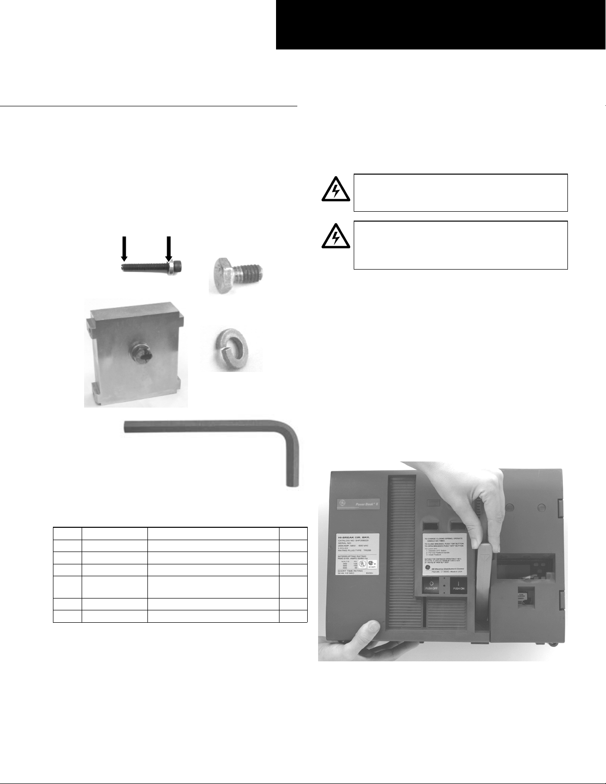
included in this kit are illustrated in
1. In the following instructions and figures, numbers in
brackets refer to the items in Table 1.
[1]
[3]
Figure 1:Parts included in the stop block gasket kit
Item Part # Description Qty.
1
N170P19024 SPRING ASSEMBLY SCREW 1
2 192A6368P1 SPACER 1
3 10054595G1 ASSEMBLY, STOP BLOCK 1
4 192A6976P233 BOLT, N22P21008B6 W/NYLON
5 N405P41B6 LOCKWASHER, STL SPRING 1/4 4
6 10103378P1 5/32 ALLEN WRENCH TOOL 1
Table 1. Parts list for the stop block gasket kit.
PATCH
Figure 1 and listed in Table
[2]
[6]
[4]
[5]
4
Installation
WARNING: Before beginning this procedure, turn
the breaker
sources, and discharge the closing springs.
AVERTISSEMENT: Mettre le disjoncteur à OFF , le
débrancher de toutes les sources de tension et
déclencher les ressorts de fermeture avant
d'entamer cette procédure.
1. Turn the breaker off and discharge the closing spring by
depressing the
ON-OFF. Verify that the breaker OFF-ON indicator shows
OFF on a green background and that the charge
indicator shows
2. A draw-out and stationary-mounted breaker need not
be removed from their enclosures, but be careful that all
primary and control power to the breakers are
disconnected.
3. Loosen the four #8-32 screws that attach the trim plate
to the breaker, if present, and remove the trim plate.
4. Loosen the four screws at the corners of the breaker
cover. Operate the charging handle one time and hold it
extended to remove the cover from the breaker face, as
illustrated in
OFF, disconnect it from all voltage
OFF and ON buttons in the sequence OFF-
DISCHARGED on a white background.
Figure 2.
Figure 2: Removing or installing the breaker top cover.
Page 2
5. Operate the charging handle four more times (for a total
of five, one less than the six needed to fully charge the
closing spring). If the closing spring does not charge, use
the following steps:
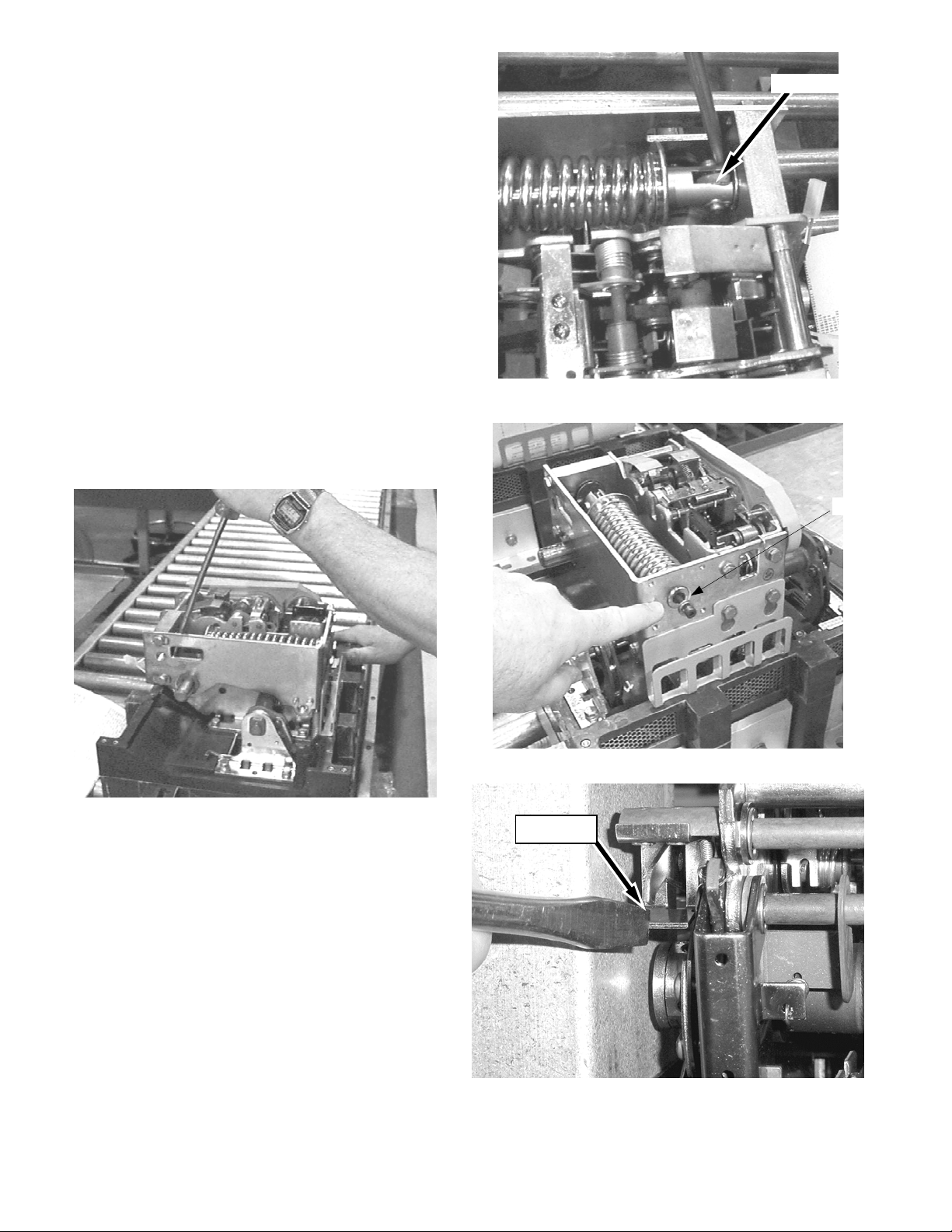
a. With a large screwdriver, put pressure on the end of
the closing spring, as shown in
Figure 3 and Figure 4.
b. Maintain pressure with the screwdriver while
operating the charging handle one time.
c. Remove the screwdriver and operate the handle four
more times.
6. Install the spring assembly screw [1] with spacer [2] at
the end of the spring assembly, as shown in
5
with the supplied
/32 Allen Wrench tool [6].
Figure 5
7. Release the closing spring by pressing the close de-latch
lever with a screwdriver, as shown in
Figure 6. Then
press the lever nearest the spring to release the breaker
mechanism, as shown in
Figure 8.
8. Using a screwdriver pull the ratchet arm away from the
sprocket to allow for the shaft mechanism to rotate
freely (
Figure 10). While holding the ratchet arm away
from the sprocket, press the spring against the stop
block as shown in
spring assembly up and out, as shown in
Figure 11, then lift the front end of the
Figure 12.
Screwdriver
Figure 4: Application point of screwdriver.
[1, 2]
Figure 3: Applying pressure to the end of the closing spring.
Figure 5: Installing the spring assembly screw.
Close De-latch
Lever
Figure 6: Pressing the close de-latch lever to release the
closing spring.
Page 3
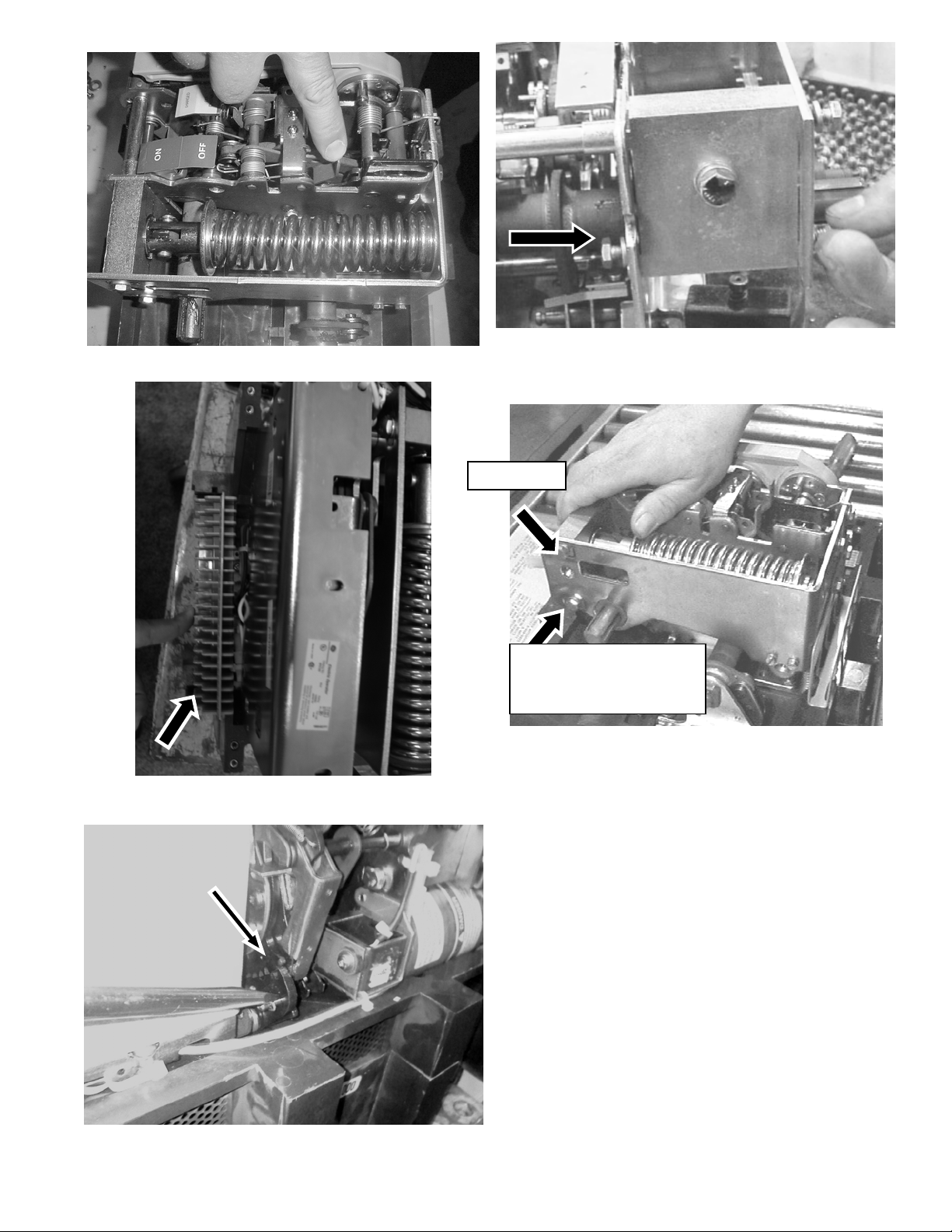
Figure 8: Releasing the breaker mechanism.
Figure 7: Illustration of Bolt on Handle Si de of Assem bl y
Wall
Front Bolt
Rear Bolt
(Not Present with
Electric Operator
Figure 11: Pressing the spring assembly to allow removal.
Figure 9: Secondary Connections Piece to be Removed Before
Electric Operator
Figure 10: Illustration of ratchet arm being pulled away from
sprocket
9. If the Electric Operator is installed on a stationary
breaker it must be detached before the Stop Block is
replaced. First remove the gray plastic secondary
connection piece from the left side of the breaker (
). Remove the two long Phillips screws and external
9
Figure
tooth lock washers from the left side of the Electric
Operator (
Figure 22 & Figure 23) with a #3 Phillips
screwdriver.
10. If working on the stationary model, support the Electric
Operator with your hand so it does not fall following the
next step. Remove the two smaller hex screws and split
lock washers from the silver bottom plate that secures
the Electric Operator to the assembly walls (
Figure 23).
The Electric Operator may now be set-aside without
disconnecting the electric snap connections. The Drawout model only requires that the electric operator be slid
7
to the left slightly allowing for a
the bolt on the side of the assembly wall (
/16 wrench to access
Figure 21 &
Figure 22).
11. Remove the front and rear bolts that secure the stop
block to the left side of the spring assembly wall (
), and the bolt securing the stop block assembly to the
11
Figure
Page 4

handle side of the assembly wall (Figure 10). If Electric
Operator is installed, then only the front and handle side
bolts will need to be removed because the rear bolt will
not be installed.
12. Loosen any screws on the front face of the accessories
Figure 13) until the screws are fully loosened from the
(
housing, and then loosen the ¼-in setscrews located on
the side of the shunt trip guide housing (
Figure 14). This
will allow the guide housing and accessories to be
removed.
13. Using the supplied
long bolt (BH HEX SKT
the structure as seen in
5
/32 Allen Wrench [6], unscrew the
1
/4-20 X 3.56 SCREW) located on
Figure 15 from the stop block
but it is not necessary to fully remove from the Spacer
Side Frame Pin tubing with collar that it passes through.
14. Wedge a flat head screwdriver between the spring
frame bearing and shaft and then rotate 90 degrees in
order to deflect the left side of the spring assembly wall
outward (
block (
Figure 16) to allow for the removal of the stop
Figure 17).
15. Discard the currently installed stop block, replace with
the new stop block assembly [3], and secure with the
three new Bolts with nylon patch [4] with Steel Spring
Lock Washers [5] on each to 65 inch-pounds min. For
models with the Electric Operator only replace the front
and handle side bolts. Ensure that the holes in the new
stop block align with the screw holes in the assembly to
avoid installing the new stop block incorrectly. Looking
at the block with the stop block gasket facing down,
there should be three holes on the left side of the stop
block and two holes on the right side.
16. Screw in the long bolt as seen in
Figure 15 with a 5/32
Allen Wrench [6] to 90 inch-pounds min., and secure the
Shunt Trip guide casing and unit back into place.
17. Align the charging spring back in position, as shown in
Figure 8.
18. Operate the breaker-charging handle five times.
Remove the spring assembly screw [1] and spacer [2]
from the end of the spring.
19. Press on the close de-latch lever with a screwdriver,
rotating it clockwise as seen from the handle side of the
breaker, as shown in
Figure 19. Then, with another
screwdriver, rotate the close de-latch mechanism to
release the charging pawl.
20. Rotate the trip de-latch lever fully back against the
frame, as shown in
Figure 20, while pressing down on
the cradle to release the closing mechanism. While
holding the cradle down, rotate the spring forward
against the stop block.
Figure 12: Spring Removed Up and Out of Assembly.
Shunt Trip Screw
Figure 13:Shunt Trip Screw to be Unscrewed
¼-in Setscrews
Figure 14: 2 Setscrews
Page 5
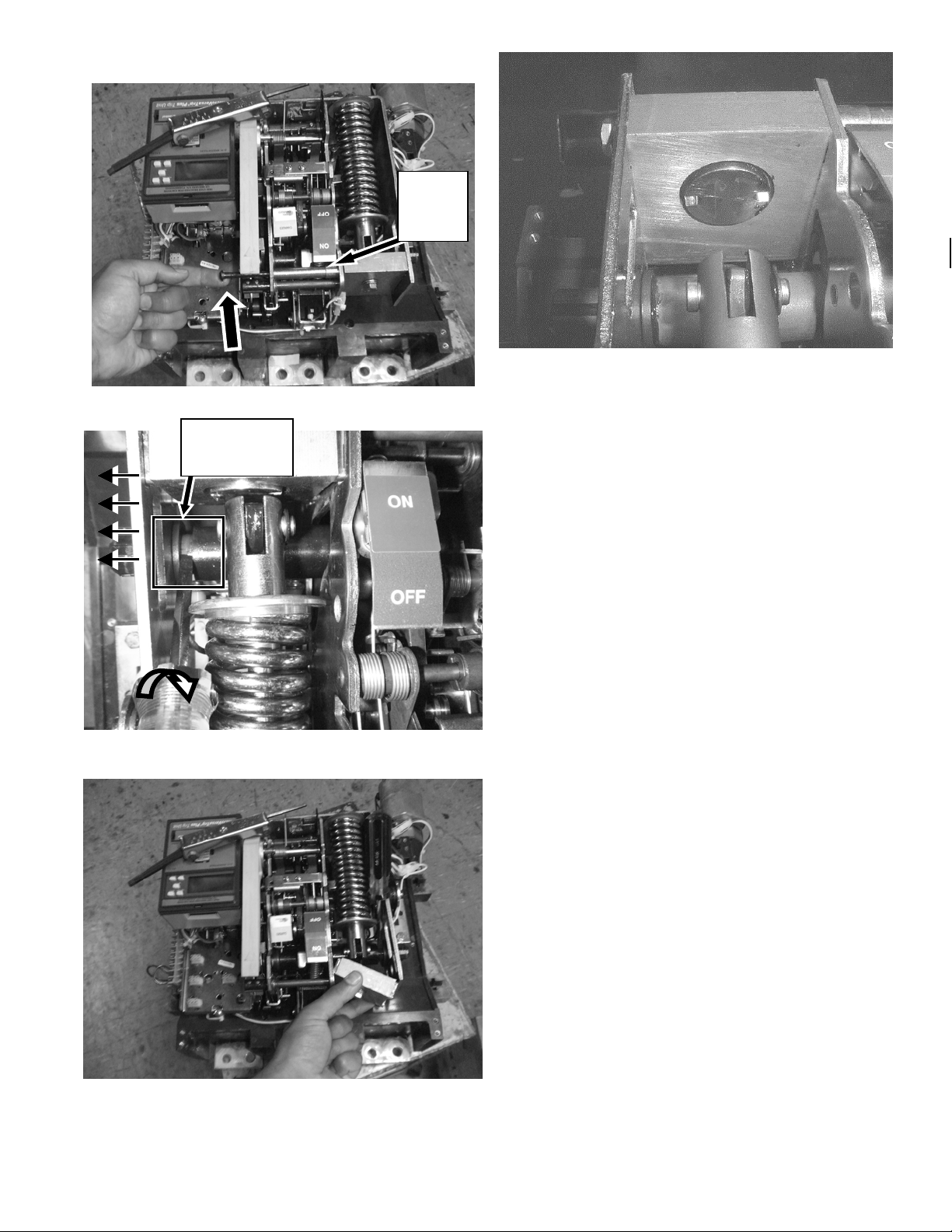
Tubin
g with
Collar
Figure 15: Allen Screw to be loosened for Stop Block Removal
Spring
Frame
Figure 18: Stop block in position in breaker.
21. Replace the Electric Operator if previously removed by
securing with the long screws on the left side of the
spring assembly wall and the short hex screws on the
bottom of the spring assembly (
Figure 23).
22. Operate the charging handle one more time to fully
charge the spring, then close and trip the breaker.
23. Operate the charging handle once and hold the handle
extended while reinstalling the breaker top cover, as
shown in
Figure 2. Tighten the four #10-32 screws to 15
in-lb.
24. Replace the trim plate, if present, and tighten the four
#8-32 mounting screws to 20 in-lb.
25. Operate the charging handle until the spring is
completely charged. Close and trip the breaker.
26. Return the breaker to operation.
Figure 16: Screwdriver Placement for Deflection of Assembly
Wall
Figure 17: Removal of Stop Block Assembly
Page 6

Figure 19: Rotating the close de-latch mechanism to release
7
/
the charging pawl.
Figure 21: Draw-out Breaker with Electric Operator
Figure 20: Reinstalling the closing spring.
Left Side View
Front View
Bolt
Electric
Figure 22: Electric Operator Slid Left on Draw-out Breaker after long Phillips screws unscrewed
Page 7

W
Long Phillips
Screws &
External
Tooth Lock
Split
Lock
Silver Bottom Plate
asher
Hex Screws
Figure 23: Electric Operator Diagram
These instructions do not cover all details or variations in equipment nor do they provide for every possible contingency that may
be met in connection with installation, operation, or maintenance. Should further information be desired or should particular
problems arise that are not covered sufficiently for the purchaser’s purposes, the matter should be referred to the GE Company.
g
GE Industrial Systems
General Electric Company
41 Woodford Ave., Plainville, CT 06062
DEH40466 R04 1004 © 2003 General Electric Company
 Loading...