

Page 1
g
GEH–6281E
Power Break® II Circuit Breaker
Accessories
Motor Operator Mechanism
Introduction
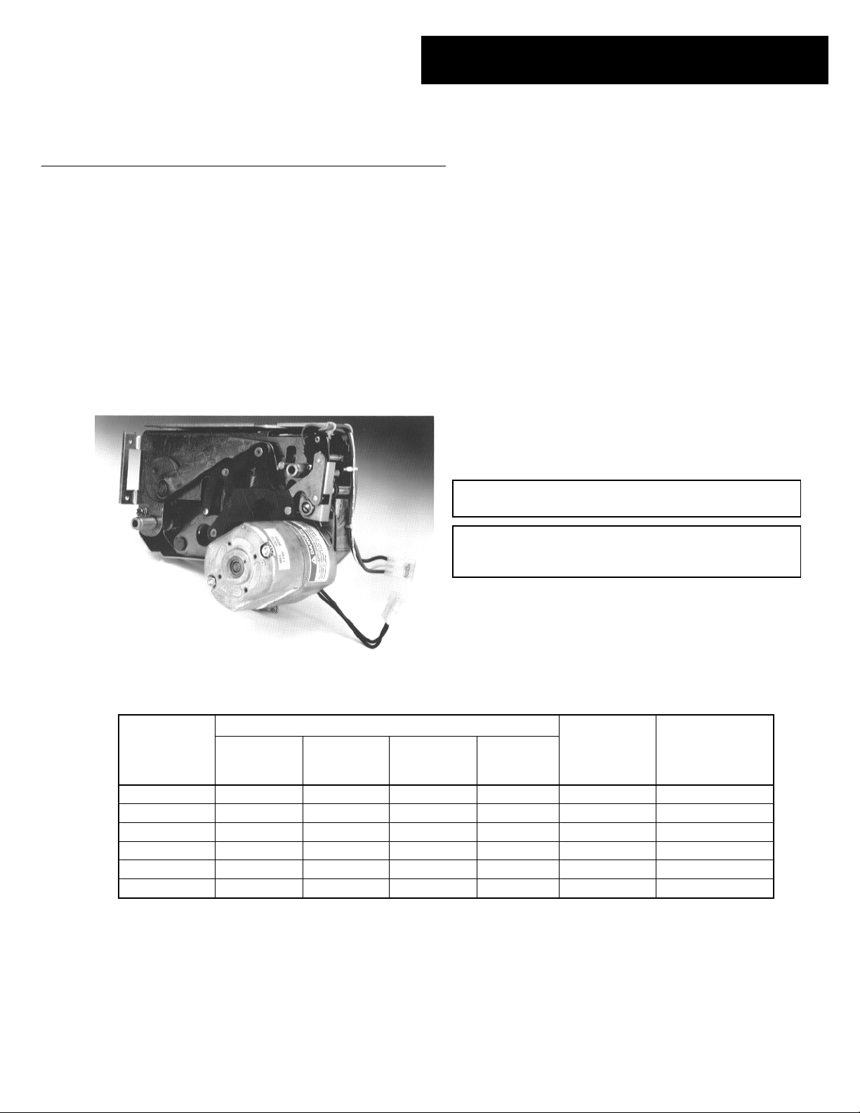
The Motor Operator Mechanism, shown in Figure 1, can
be installed in 800–4000 A frame Power Break® II circuit
breakers. It provides a means of remotely or
automatically charging the springs that close the breaker.
Table 1 lists the catalog numbers and corresponding
electrical data for the available models. Note that the
Remote Close and Shunt Trip accessories are not
included with the Motor Operator Mechanism; they must
be ordered separately.
Remote Operation
The circuit breaker closing springs can be charged
remotely by shorting terminals 17 and 35 on the terminal
block on the right side of the breaker, with a push button
or similar device, for a minimum of five seconds. Power
for the Motor Operator must also be applied to terminals
18 and 36, as shown in the wiring diagram in Figure 6.
Automatic Operation
Connect terminals 17 and 35 on the terminal block on
the right side of the breaker with a jumper wire. The
Motor Operator will automatically recharge the breaker
closing springs whenever the breaker closes.
CCCCAAAAUUUUTTTTIIIIOOOONNNN::
charge and automatic close.
AAAATTTTTTTTEEEENNNNTTTTIIIIOOOONNNN::
tous les deux l’armement automatique et la fermeture
automatique.
::
Do not wire breakers for both automatic
::
Ne pas câbler les disjoncteurs pour
Figure 1. Motor Operator Mechanism.
Control
Rated Voltage
(50–60 Hz) Voltage
Rating
24 Vdc 21–27 Vdc 30.0 14.0 11.0 3.0 (nom) 12 A, 125 V
48 Vdc 41–53 Vdc 18.0 7.0 4.5 3.0 (nom) 7 A, 125 V
72 Vdc 62–80 Vdc 10.0 4.5 3.0 3.0 (nom) 5 A, 125 V
120 Vac 102–132 Vac 7.5 4.0 2.0 3.0 (nom) 4 A, 125 V
125 Vdc 106–137 Vdc 8.0 2.5 1.8 3.0 (nom) 2.5 A, 125 V
240 Vac 204–264 Vac 6.0 2.5 1.0 3.0 (nom) 2.5 A, 250 V
➀
Charging times apply to nominal voltage only; times may vary at maximum and minimum voltages.
Peak Inrush
Current, A
Table 1. Electrical data for the Motor Operator Mechanism.
Peak
Full-Load
Current, A
Average
Current, A
Charge Time
(sec)
➀
Recommended
Fuse (Slo-Blo)
Page 2
Power Break® II Motor Operator Mechanism
Installation in 800–4000 A Stationary Breaker
Installation in 800–4000 A Stationary
Breaker
::
WWWWAAAARRRRNNNNIIIINNNNGGGG::
breaker off, disconnect it from all voltage sources, and
discharge the closing springs.
Before installing any accessories, turn the
AAAAVVVVEEEERRRRTTTTIIIISSSSSSSSEEEEMMMMEEEENNNNTTTT::
mettre le disjoncteur en position OFF, le déconnecter de
toute tension d’alimentation, et décharger les ressorts
d’armement.
Use the following procedure to install the Motor Operator
Mechanism onto a stationary circuit breaker.
1111....Verify that the rating on the Motor Operator
Mechanism identification plate matches the
voltage rating required for the application, as
listed in Table 1.
2222....Check that the package contains all the parts listed
in Table 2. If any components are missing, contact
the ED&C Customer Support Center at 800-843-
3742. Note that the Remote Close and Shunt Trip
accessories are not included with the Motor
Operator Mechanism; they must be ordered
separately.
DDDDeeeessssccccrrrriiiippppttttiiiioooonn
Motor Operator Assembly 1
1
⁄4-20 x 3-inch Flat-Head Screw 2
1
⁄4-inch Conical Lock Washer 2
Mounting Bracket 1
#10-32 x 1⁄4 inch Screw 6
#10 Lock Washer 6
Labels 2
Table 2. Parts list for the Motor Operator Mechanism.
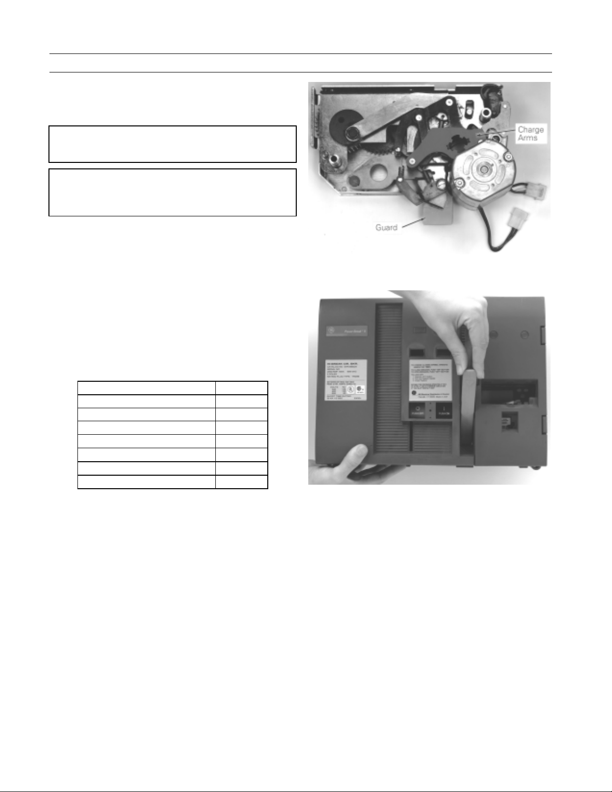
3333....Verify that the charge arms of the Motor Operator
Mechanism are in the discharged position, as
illustrated in Figure 2.
4444....Turn the breaker off and discharge the closing
spring by depressing the OFF and ON buttons in
the sequence OFF-ON-OFF. Verify that the breaker
OFF-ON indicator shows OFF on a green
background and that the charge indicator shows
DISCHARGED on a white background.
5555....Loosen the four #8-32 screws on the trim-plate
assembly and remove the trim plate.
6666....Loosen the four screws at the corners of the breaker
cover. Crank the operating handle one time and
hold it extended to remove the cover from the
breaker face, as illustrated in Figure 3. The Motor
Operator can be safely installed with such a
partially charged mechanism.
::
Avant d’installer tout accessoire,
nn
QQQQuuuuaaaannnnttttiiiittttyy
yy
Figure 2. Motor Operator Mechanism charge arms in the discharged
position.
Figure 3. Removal of the breaker top cover.
7777....Remove the screw holding the left secondary
terminal block to the midcover and lift the terminal block up and away from its mounting ridge
on the midcover.
8888....Install the Remote Close accessory at this time if
the breaker is to be equipped with this option.
9999....RRRReeeemmmmoooovvvveeee aaaannnndddd ddddiiiissssccccaaaarrrrdddd tttthhhheeee bbbboooottttttttoooommmm ssssccccrrrreeeewwww,,
sssshhhhoooowwwwnnnn iiiinnnn FFFFiiiigggguuuurrrreeee 4444,,,, tttthhhhaaaatttt aaaattttttttaaaacccchhhheeeessss tttthhhheeee ssssttttoooopp
bbbblllloooocccckkkk ttttoooo tttthhhheeee sssspppprrrriiiinnnngggg ffffrrrraaaammmmeeee..
11110000....Position the charge interlock rod of the breaker
down against the midcover.
11111111....While holding the charge arm of the Motor
Operator Mechanism in the discharged position,
align the splined closing shaft of the breaker with
the splined cutout in the hub of the charge arm, as
shown in Figure 4. Tilt the right end of the
mechanism up so that the guard (see Figure 2)
clears the lip on the side of the breaker, as shown
in Figure 5. Push the Motor Operator Mechanism
in past the lip, rotate it back down, then push it
..
,,
pp
2
Page 3

Power Break® II Motor Operator Mechanism
onto the breaker until the spacers engage the
spring frame and the stop block.
11112222....Attach the Mounting Bracket to the four holes
opposite the stop block on the spring frame with
#10-32 screws tightened to 32 in-lb torque. The
bend of the bracket must be outward from the
spring frame.
11113333....Align the two holes in the Mounting Bracket with
the two holes in the Motor Operator Mechanism
and attach with two #10-32 screws tightened to 32
in-lb torque.
11114444....Thread a
washer through the spacer and into the stop block,
as illustrated in Figure 4. Thread the other
flat-head screw and conical lock washer through
the spacer into the captive nut in the spring frame.
Tighten both screws to 70 in-lb.
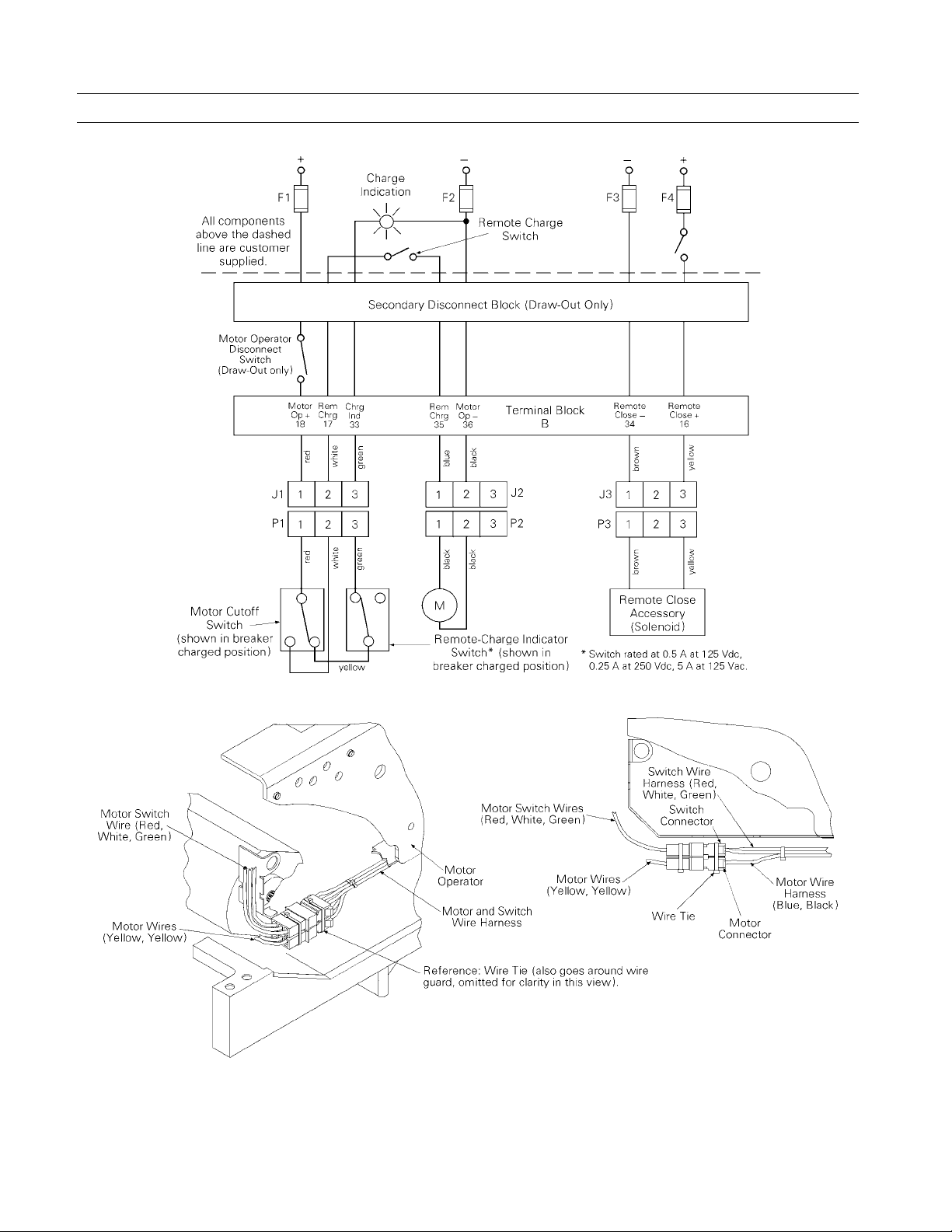
11115555....Plug the color-coded, numbered Motor Operator
Mechanism wires into the corresponding numbered sockets, as illustrated in Figure 6. Mating
connector wires are installed at the factory and are
located in the gray-painted channel, shown in
Figure 5
11116666....Dress the wires and install cable ties as shown in
the illustration in Figure 7. Ensure that wires are
clear of all moving parts.
11117777....Reinstall the secondary terminal block onto the
breaker midcover terminal block mounting ridge
and fasten with the screw previously removed.
11118888....Crank the operating handle once and hold the
handle extended to reinstall the breaker top cover.
Tighten the four #10-32 mounting screws to 15 inlb.
11119999....Replace the trim plate and tighten the four #8-32
screws to 20 in-lb.
22220000....Affix the accessory rating label to the breaker cover
above the right-side secondary terminal block.
22221111....Affix the “Electrically Operated” label to the top
cover over the knock-out space above the ON-OFF
indicator flag.
22222222....Crank the operating handle until the closing
springs are completely charged.
22223333....Close and trip the breaker.
22224444....Test the Motor Operator Mechanism electrically
according to Table 1.
1
⁄4–20 flat-head screw and conical lock
1
⁄4–20
Installation in 800–4000 A Stationary Breaker
Figure 4. Installing the Motor Operator Mechanism onto the breaker.
Motor Operator
Wires in Gray
Channel
Guard
Lip
Figure 5. Rotating the Motor Operator Mechanism so that the guard
clears the lip on the side of the circuit breaker.
3
Page 4
Power Break® II Motor Operator Mechanism
Installation in 800–4000 A Stationary Breaker
Figure 6. Wiring diagram of the Motor Operator Mechanism and Remote Close accessories.
Figure 7. Installing the Motor Operator wires.
4
Page 5

Power Break® II Motor Operator Mechanism
Installation in 800–2000 A Draw-Out
Breaker
Installation in 800–2000 A Draw-Out Breaker
WWWWAAAARRRRNNNNIIIINNNNGGGG::
breaker off, disconnect it from all voltage sources, and
discharge the closing springs.
AAAAVVVVEEEERRRRTTTTIIIISSSSSSSSEEEEMMMMEEEENNNNTTTT::
mettre le disjoncteur en position OFF, le déconnecter
de toute tension d’alimentation, et décharger les
ressorts d’armement.
Use the following procedure to install the Motor Operator
Mechanism onto an 800–2000 A draw-out circuit breaker.
1111....Verify that the rating on the Motor Operator
2222....Check that the package contains all the parts listed
3333....Verify that the charge arms of the Motor Operator
4444....Turn the breaker off and discharge the closing
5555....Engage the
6666....Pull the substructure rails out as far as possible
7777....From the DISCONNECTED position, pull the
8888....Attach the Lifting Bar, catalog number TDOLB, by
9999....Remove the breaker from the draw--out substruc-
11110000....Loosen the four #8-32 screws on the trim-plate
::
Before installing any accessories, turn the
::
Avant d’installer tout accessoire,
Mechanism identification plate matches the
voltage rating required for the application, as
listed in Table 1.
in Table 2. If any components are missing, contact
the ED&C Customer Support Center at 800-843-
3742. Note that the Remote Close and Shunt Trip
accessories are not included with the Motor
Operator Mechanism; they must be ordered
separately.
Mechanism are in the discharged position, as
illustrated in Figure 2.
spring by depressing the OFF and ON buttons in
the sequence OFF-ON-OFF. Verify that the breaker
OFF-ON indicator shows OFF on a green
background and that the charge indicator shows
DISCHARGED on a white background.
1
⁄ 2 -inch square end of the racking
shaft with the supplied wrench, catalog number
TDORT, as illustrated in Figure 8, and rotate the
shaft counter-clockwise to withdraw the breaker to
the DISCONNECTED position.
until they drop into the horizontal locked position,
as illustrated in Figure 9.
breaker out on the rails until the front rollers fall
into the detent.
locating the hooks on the bar beneath the shoulder
studs on the breaker, as illustrated in Figures 10
and 11.
ture and place it on a suitable work surface.
assembly, if so equipped, and remove the trim
plate. If stand-offs are also installed, remove those
as well.
Racking
Tool
Figure 8. Wrench attached to the breaker racking shaft.
Figure 9. Withdrawing the substructure rails.
Pipe
Lifting Bar
Shoulder
Stud
Figure 10. Lifting Bar attached to the breaker for manual lifting.
5
Page 6

Power Break® II Motor Operator Mechanism
Installation in 800–2000 A Draw-Out Breaker
11111111....Loosen the four screws at the corners of the breaker
cover. Crank the operating handle one time and
hold it extended to remove the cover from the
breaker face, as illustrated in Figure 3. The Motor
Operator can be safely installed with such a
partially charged mechanism.
11112222....Remove the retaining screw and snap ring (using
an appropriate snap ring pliers) that hold the
chain guard in place on the rear of the breaker, as
shown in Figure 12, then remove the guard.
11113333....Remove the two screws holding the breaker side
plate in place, as shown in Figure 13.
11114444....Tilt the side plate away from the breaker, then
remove the racking chain from the gear, as shown
in Figure 14.
11115555....Remove the screw holding the secondary terminal
block to the midcover, as illustrated in Figure 15,
and lift the terminal block up and away from its
mounting ridge.
11116666....Turn the breaker so that it is resting on the
primary disconnects, as illustrated in Figure 16. Be
careful not to lose the white nylon plunger that will
fall out from the back of the breaker, as it must be
reinstalled when the breaker is reassembled.
11117777....Follow steps 8 to 17 in the installation procedure
for the stationary breaker.
11118888....Turn the breaker to its original position, carefully
reinserting the nylon plunger in the rear of the
breaker.
11119999....Replace the chain on the gear, then tilt the side
plate back into place. Replace the two mounting
screws, tightening them to 70 in-lb.
22220000....Replace the chain guard and fasten it in place with
the retaining screw and snap ring removed earlier.
22221111....Crank the operating handle once and hold the
handle extended to reinstall the breaker top cover.
Tighten the four #10-32 mounting screws to 15 inlb.
22222222....Replace the trim plate and tighten the four #8-32
screws to 20 in-lb.
22223333....Affix the accessory rating label to the breaker cover
above the right-side secondary terminal block.
22224444....Affix the “Electrically Operated” label to the top
cover over the knock-out space above the ON-OFF
indicator flag.
22225555....Crank the operating handle until the closing
springs are completely charged.
22226666....Close and trip the breaker.
22227777....Test the Motor Operator Mechanism electrically
according to Table 1.
Figure 11. Lifting Bar attached to the breaker for lifting with a hoist.
Figure 12. Locations of the retaining screw and snap ring on the chain
Snap
Ring
Retaining
Screw
guard.
Side Plate
Screws
Figure 13. Two screws to be removed from the breaker side plate.
6
Page 7

Power Break® II Motor Operator Mechanism
22228888....Reattach the breaker lifting bar, as illustrated in
Figures 10 and 11.
22229999....Pull out the substructure rails until they drop into
the horizontal locked position. Lower the breaker
so that the grooves in the rollers drop over the
rails.
33330000....Ensure that the grooves in all rollers straddle the
rails, then remove the Lifting Bar and push the
breaker into the substructure until it stops in the
DISCONNECTED position. Then lift the rails and
push them into the stored position.
22228888....Engage the 1⁄2-inch square end of the racking shaft
with the supplied wrench and rotate the shaft
clockwise to draw the breaker into the TEST or
CONNECTED position, as illustrated in Figure 8.
Installation in 800–2000 A Draw-Out Breaker
Terminal
Block
Screw Location
800–2000 A
Screw Location
2500–4000 A
Chain
Figure 15. Removing the screw holding the secondary terminal block in
place.
Figure 14. Racking chain removed from the gear.
Nylon
Plunger
Figure 16. Breaker resting on its back, ready for installation of the
Motor Operator Mechanism.
7
Page 8

Power Break® II Motor Operator Mechanism
Installation in 2500–4000 A Draw-Out Breaker
Installation in 2500–4000 A Draw-Out
Breaker
::
WWWWAAAARRRRNNNNIIIINNNNGGGG::
breaker off, disconnect it from all voltage sources, and
discharge the closing springs.
AAAAVVVVEEEERRRRTTTTIIIISSSSSSSSEEEEMMMMEEEENNNNTTTT::
mettre le disjoncteur en position OFF, le déconnecter de
toute tension d’alimentation, et décharger les ressorts
d’armement.
Use the following procedure to install the Motor Operator
Mechanism onto a 2500–4000 A draw-out circuit breaker.
1111....Verify that the rating on the Motor Operator
Mechanism identification plate matches the
voltage rating required for the application, as
listed in Table 1.
2222....Check that the package contains all the parts listed
in Table 2. If any components are missing, contact
the ED&C Customer Support Center at 800-843-
3742. Note that the Remote Close and Shunt Trip
accessories are not included with the Motor
Operator Mechanism; they must be ordered
separately.
3333....Verify that the charge arms of the Motor Operator
Mechanism are in the discharged position, as
illustrated in Figure 2.
4444....Turn the breaker off and discharge the closing
spring by depressing the OFF and ON buttons in
the sequence OFF-ON-OFF. Verify that the breaker
OFF-ON indicator shows OFF on a green
background and that the charge indicator shows
DISCHARGED on a white background.
5555....Engage the 1⁄ 2 -inch square end of the racking
shaft with the supplied wrench, catalog number
TDORT, as illustrated in Figure 8, and rotate the
shaft counter-clockwise to withdraw the breaker to
the DISCONNECTED position.
6666....Attach a Lifting Bar, catalog number TDOLB, by
locating the hooks on the bar beneath the shoulder
studs on the breaker, as illustrated in Figure 11.
7777....Remove the breaker from the draw-out substructure
and place it on a suitable work surface. Place the
breaker on supports so that the weight of the
breaker is not supported by the side plates, as
shown in Figure 17.
8888....Loosen the four #8-32 screws on the trim-plate
assembly, if so equipped, and remove the trim
plate. If stand-offs are also installed, remove those
as well.
9999....Loosen the four screws at the corners of the breaker
cover. Crank the operating handle one time and
hold it extended to remove the cover from the
breaker face, as illustrated in Figure 3. The Motor
Operator can be safely installed with such a
partially charged mechanism.
Before installing any accessories, turn the
::
Avant d’installer tout accessoire,
Secondary
Disconnect Screws
Wire
Ties
Side
Clip
Upper Mounting
Side Plate
Bolts
Mounting Tab
Tab (Under Clip)
Lower
Figure 17. 2500–4000 A draw-out breaker side panel, showing the wire
ties, bolts, and clip to be removed.
11110000....Remove the retaining screw and snap ring (using
an appropriate snap ring pliers) that hold the
chain guard in place on the rear of the breaker, as
shown in Figure 12, then remove the guard. Be
careful not to lose the white nylon interlock
plunger that may fall out of the back of the
breaker, as it must be reinstalled when the breaker
is reassembled.
11111111....Rotate the chain until the removable link, shown in
Figure 18, is accessible on the chain drive
sprocket. Slide a screwdriver blade into the
retaining clip and pry one side up, as shown, then
remove the clip by sliding the clip off the pins.
Remove the two parts of the link, then remove the
chain from the drive sprocket.
11112222....Remove the wire ties that hold the wire bundle
connected from the secondary disconnect to the
breaker side plate, shown in Figure 17. Remove the
screw and clip, also shown in Figure 17. Remove
the two 3⁄ 8 -16 bolts directly above and below the
chain drive sprocket.
11113333....Remove the two screws in the secondary disconnect
mounting bar indicated in Figure 17, then slide
the secondary disconnect and the two rods toward
the front of the breaker and lift them out and away
from the side plate.
8
Page 9

Power Break® II Motor Operator Mechanism
11114444....Remove the screw holding the secondary terminal
block to the midcover, as illustrated in Figure 15.
Lift the terminal block off its mounting ridge.
11115555....Push the bottom rear of the side plate away from
the breaker, then hit the lip at the front of the side
plate (toward the front of the breaker) with a
rubber mallet until the bottom mounting tab is free
from its retainer. The top mounting tab should
then come off easily. Set the side plate aside.
11116666....Install the Remote Close accessory at this time, if
the breaker is to be equipped with this option.
11117777....RRRReeeemmmmoooovvvveeee aaaannnndddd ddddiiiissssccccaaaarrrrdddd tttthhhheeee bbbboooottttttttoooommmm ssssccccrrrreeeewwww tttthhhhaaaatt
aaaattttttttaaaacccchhhheeeessss tttthhhheeee ssssttttoooopppp bbbblllloooocccckkkk ttttoooo tttthhhheeee sssspppprrrriiiinnnngg
ffffrrrraaaammmmeeee,,,, sssshhhhoooowwwwnnnn iiiinnnn FFFFiiiigggguuuurrrreeee 4444..
11118888....Attach the mounting bracket, as shown in Figures 4
and 19, with four #10-32 screws tightened to 32 inlb torque. The bend of the bracket must be
outward from the spring frame.
11119999....Align the splined closing shaft of the breaker with
the splined cutout in the hub of the Motor
Operator Mechanism charge arm, as shown in
Figure 20.
22220000....Push the Motor Operator Mechanism into the
breaker until the spacers engage the spring frame
and the stop block.
22221111....Align the two holes in the mounting bracket with
the two holes in the Motor Operator Mechanism
and attach with two #10-32 screws tightened to 32
in-lb torque.
22222222....Thread a 1⁄4–20 flat-head screw and conical lock
washer through the spacer and into the stop block,
as illustrated in Figure 4. Thread the other 1⁄4–20
flat-head screw and conical lock washer through
the spacer into the captive nut in the spring frame.
Tighten both screws to 70 in-lb.
22223333....Plug the color-coded, numbered Motor Operator
Mechanism wires into the corresponding numbered sockets on the wires coming from the secondary terminal block, as illustrated in Figure 6.
22224444....Reinstall the secondary terminal block onto the
breaker midcover and fasten with the screw previously removed.
22225555....Replace the cable ties holding the secondary dis-
connect wires to the side plate, as shown in Figure
21.
..
Installation in 2500–4000 A Draw-Out Breaker
tt
gg
Figure 18. Use a screwdriver blade to pry off the clip holding the
removable chain link in place.
Splined
Shaft
Mounting
Bracket
Figure 19. Mounting bracket attached to the stop block on the spring
frame.
Splined
Shaft
Motor
Operator
Figure 20. Motor Operator Mechanism aligned with the splined shaft in
the breaker.
9
Page 10

Power Break® II Motor Operator Mechanism
Installation in 2500–4000 A Draw-Out Breaker
22226666....Line up the bottom mounting tab on the breaker
side plate with the raised retainer on the side of
the breaker, then hit the bottom of the lip at the
front of the side plate with a rubber mallet to seat
the tab. Line up the upper tab with its retainer and
hit the top of the side plate lip with the mallet to
seat the tab.
22227777....Attach the two bolts, nuts, and lock washers
holding the side frame to the breaker and tighten
to 300 in-lb.
22228888....Attach the clip to the upper mounting tab retainer
with the screw removed earlier.
22229999....Put the chain back on its drive gear and hold it in
place with the two parts of the removable link. With
a screwdriver blade, pry the retaining clip apart
and slide it over the two exposed pins, as shown in
Figure 18 (the reverse of removal).
33330000....Ensure that the white nylon interlock plunger is
properly installed in the rear of the breaker.
Replace the chain guard and fasten it in place
with the retaining screw and snap ring removed
earlier.
33331111....Slide the two steel rods through the holes in the
secondary disconnect and into the mounting holes
in the side frame. Insert the other ends of the rods
into the mounting bar and attach the bar to the
side plate with the two screws removed earlier.
33332222....Crank the operating handle once and hold the
handle extended to reinstall the breaker top cover.
Tighten the four #10-32 mounting screws to 15 inlb.
33333333....Replace the trim plate and tighten the four #8-32
screws to 20 in-lb.
33334444....Affix the accessory rating label to the breaker cover
above the right-side secondary terminal block.
33335555....Affix the “Electrically Operated” label to the top
cover over the knock-out space above the ON-OFF
indicator flag.
33336666....Crank the operating handle until the closing
springs are completely charged.
33337777....Close and trip the breaker.
33338888....Test the Motor Operator Mechanism electrically
according to Table 1.
Figure 21. Motor Operator Mechanism installed in the breaker, showing
the side panel reattached and the cable ties replaced on the wires
Wir
e
connecting the terminal block to the secondary disconnect.
10
Page 11

Power Break® II Motor Operator Mechanism
Trouble-Shooting
The following guide is provided for trouble-shooting and
isolating common problems. It does not cover every
possible situation. Contact the ED&C Customer Support
Center at 800-843-3742 if any problem is not resolved by
these procedures.
Trouble-Shooting
SSSSyyyymmmmppppttttoooomm
The breaker does not
charge.
mm
PPPPoooossssssssiiiibbbblllleeee CCCCaaaauuuussssee
The breaker is already
charged.
Power is not available to the
Motor Operator Mechanism.
The breaker was partially
charged manually
ee
CCCCoooorrrrrrrreeeeccccttttiiiivvvveeee AAAAccccttttiiiioooonn
None.
Check that the Motor Operator Mechanism is wired
correctly, as shown in Figure 5.
Check that all connectors are properly seated.
Check that the voltage applied to the Motor Operator
Mechanism is within the specified range.
Complete the manual charging cycle until the
breaker’s charge indicator shows CHARGED.
nn
11
Page 12

t
d
p
e
g
These instructions do not cover all details or variations in equipment nor do they provide for every possible contingency tha
may be met in connection with installation, operation, or maintenance. Should further information be desired or shoul
articular problems arise that are not covered sufficiently for the purchaser’s purposes, the matter should be referred to th
GE Company.
General Electric Company
41 Woodford Ave., Plainville, CT 06062
GEH6281 R06 0397 © 1997 General Electric Company
GE Industrial Systems
 Loading...