

Page 1
g
GEH–6275D
Power Break® II Circuit Breaker
Accessories
Bell Alarm–Alarm Only
Introduction
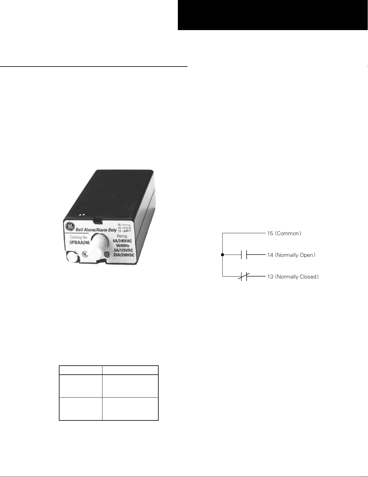
The Bell Alarm–Alarm Only module, shown in Figure 1, can be
installed in 800–4000 ampere frame Power Break® II circuit
breakers. This module pro vides a switch to remotely indicate
that the circuit breaker has tripped. It is reset either
automatically when the circuit breaker is reclosed or manually
when the reset button on the front of the Bell Alarm–Alarm
Only module is pressed.
Operation
The Bell Alarm–Alarm Only provides normally open (N O) and
normally closed (NC) outputs available at the terminal block
on the right side of the breaker, as illustrated in Figure 2. The
outputs change state whenever a breaker trip occurs. This trip
can be caused by an overcurrent condition detected by the Trip
Unit. This trip can also be generated by the Shunt Trip, Shunt
Trip with Lockout, or Undervoltage Release, if installed with a
MicroVersaTrip Plus or MicroVersaTrip PM Trip Unit and if
the appropriate DIP switches have been set on the back of the
Trip Unit. Power+ Trip Units can only activate the Bell
Alarm–Alarm Only for a protection trip.
The Bell Alarm–Alarm Only accessory resets automatically,
returning the outputs to their normal configuration, when the
breaker is reclosed. The Bell Alarm–Alarm Only can also be
reset manually, before the breaker is reclosed, by pressing the
reset button on the front of the module.
Figure 1. Bell Alarm–Alarm Only.
In addition to activation by protection trips, the Bell
Alarm–Alarm Only accessory module can be set up to interact
with other Power Break II accessories, when used with a
MicroVersaTrip Plus™ or MicroVersaTrip PM™ Trip Unit.
DIP switches on the rear of the MicroVersaTrip Plus or
MicroVersaTrip PM Trip Unit can configure the Bell
Alarm–Alarm Only accessory to activate when a Shunt Trip or
Undervoltage Release trip occurs. The Accessory Configuration
section below describes how this can be done
The Power+™ Trip Unit activates the Bell Alarm–Alarm Only
for protection trips only.
The catalog numbers for the Bell Alarm–Alarm Only are listed
in Table 1.
Catalog No. Contact Rating
6 A at 240 Vac
SPBAA240
SPBAA600
➀
600 V version is not UL listed.
Table 1. Bell Alarm–Alarm Only catalog numbers.
0.25 A at 250 Vdc
0.50 A at 125 Vdc
➀
0.25 A at 250 Vdc
0.50 A at 125 Vdc
6 A at 600 Vac
Figure 2. Bell Alarm–Alarm Only connections on the right terminal
block. The contacts are shown in the reset state.
Page 2
Installation
WARNING: Before installing any accessories, turn the breaker
OFF, disconnect it from all voltage sources, and discharge the
charging springs.
AVERTISSEMENT: Avant d’installer tout accessoire, mettre
le disjoncteur en position OFF, le déconnecter de toute tension
d’alimentation, et décharger les ressorts d’armement.
The Bell Alarm–Alarm Only is installed in the accessory
compartment on the front of the circuit breaker in the position
shown in Figure 3.
Figure 3. Accessory compartment on front of circuit breaker, with Bell
Alarm–Alarm Only slot indicated.
Use the following procedure to install the Bell Alarm–Alarm
Only into the accessory compartment:
1. Open the hinged door over the accessory compartment and
Trip Unit.
2. To remove an existing accessory module, loosen the
accessory locking screw and pull the module out with the
Rating Plug Removal Tool (catalog number TRTOOL).
3. Insert the Bell Alarm–Alarm Only module into the proper
slot, as illustrated in Figure 4. The Bell Alarm–Alarm
Only module i s keyed for the correct slot in the accessory
compartment. If the module cannot be fully seated in the
compartment, check that the compartment position is
correct.
4. Tighten the locking screw on the front of the accessory
until it is snug (9 in-lbs).
Figure 4. Inserting the Bell Alarm-Alarm Only into the accessory
compartment.
6. Connec t the control wiring for the Bell Alarm–Alarm Only
at the right terminal block, as illustrated in Figure 2.
7. Test the Bell Alarm–Alarm Only to ensure proper
operation, according to the procedures below.
8. Reconnect power to the circuit breaker and any other
accessories.
9. Close and lock or seal the door over the accessory
compartment and Trip Unit to prevent unauthor ized
changes to Trip Unit settings and to keep contaminants
out of empty accessory slots.
10. If the Bell Alarm–Alarm Only is rated at 600 V, remove
the UL label from the breaker top cover.
Accessory Configuration
This section applies only if Shunt Trip or Undervoltage Release
accessories are installed in the breaker, along with a
MicroVersaTrip Plus or MicroVersaTrip PM Trip Unit. The
Bell Alarm–Alarm Only accessory can be configured to activate
if a Shunt Trip or Undervoltage Release trip occurs. The
configuration can be changed by removing the Trip Unit from
the breaker, setting the DIP switches on the rear of the Trip
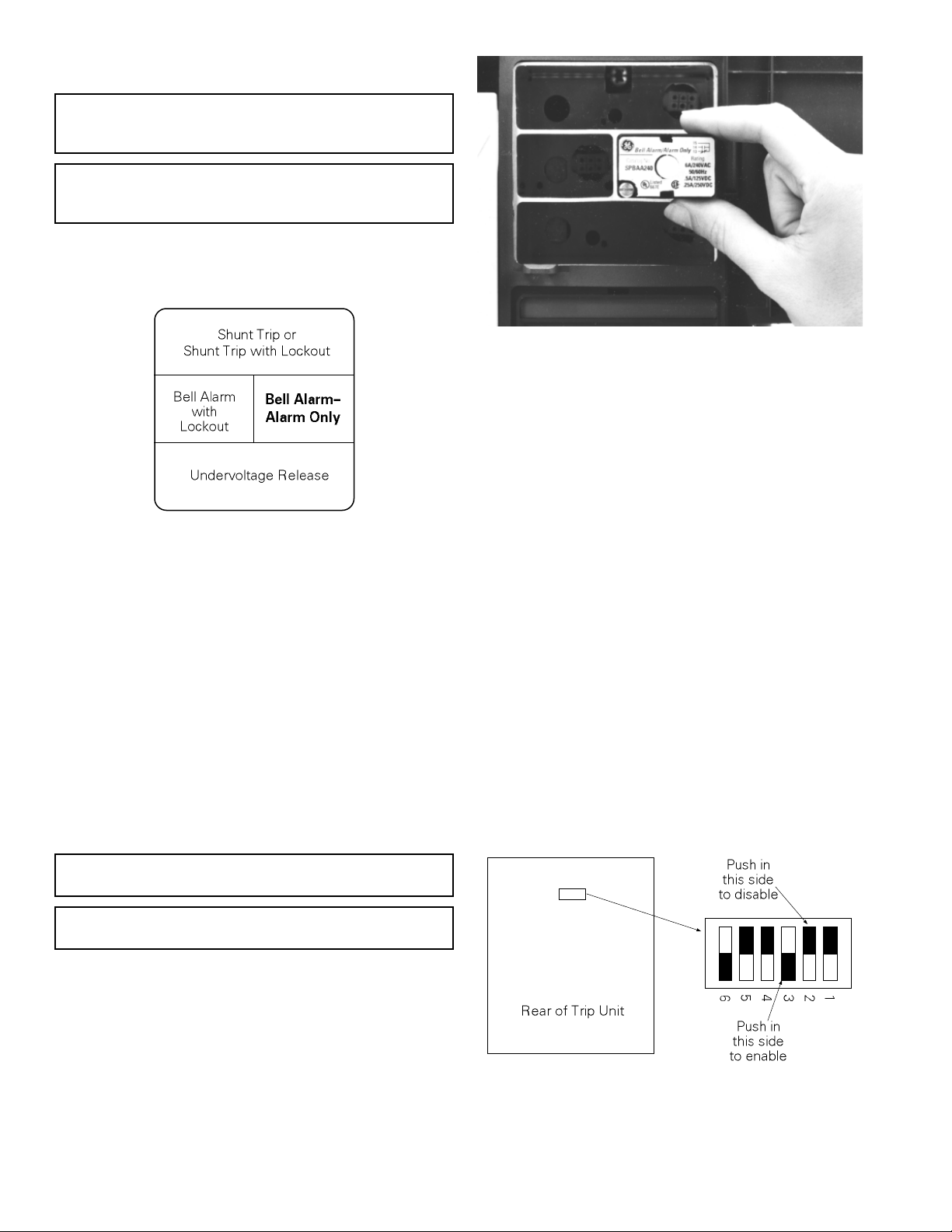
Unit, and rein stalling the Trip Unit. Figure 5 illustrates the
Trip Unit rear DIP switches. Table 2 lists the switch functions
and the factory settings for each.
CAUTION: Overtightening the locking screw may damage or
distort the ca se of the accessory.
ATTENTION: Le serrage excessif de la vis de verrouillage
peut déformer le boîtier d’accessoire.
5. If the breaker is equipped with a MicroVersaTrip Plus or
MicroVersaTrip PM Trip Unit, the Bell Alarm–Alarm
Only accessory can be confi gured to activate after trips
due to installed Undervoltage Release or Shunt Trip
accessories with the procedure described in the Accessory
Configuration section.
Figure 5. Accessory switch on the rear of a MicroVersaTrip Plus™ or
MicroVersaTrip PM™ Trip Unit, showing the factory settings (solid
part indicates that switch is pushed in on that side).
Page 3

Switch
1 Disabled
2 Disabled
3 Enabled
4 Disabled
5 Disabled
6 Enabled
Factory
Setting Function
Shunt trip activates Bell Alarm–Alarm
Only
UVR trip activates Bell Alarm–Alarm
Only
Protection trip activates Bell
Alarm–Alarm Only
Shunt trip activates Bell Alarm with
Lockout
UVR trip activates Bell Alarm with
Lockout
Protection trip activates Bell Alarm
with Lockout
Table 2. Accessory switch settings, including factory defaults.
Description of Switch Settings
Following are descriptions of the effects of each accessory switch
when it is enabled:
1. When a Shunt Trip accessory causes the breaker to trip,
the contacts of the Bell Alarm–Alarm Only also change
state. (The factory switch setting is disabled .)
2. When an Undervoltage Release accessory causes the
breaker to trip, the contacts of the Bell Alarm–Alarm Only
also change state. (The factory switch setting is disabled.)
3. When a protection trip (long-time, short-time,
instantaneous, ground-fault, or protective-relay) occurs,
the contacts of the Bell Alarm–Alarm Only also change
state. (The factory switch setting is enabled.)
4. When a Shunt Trip accessory causes the breaker to trip,
the contacts of the Bell Alarm with Lock out also change
state. (The factory switch setting is disabled .)
5. When an Undervoltage Release accessory causes the
breaker to trip, the contacts of the Bell Alarm with
Lockout also change state. (The factory switch setting is
disabled .)
6. When a protection trip (long-time, short-time,
instantaneous, ground-fault, or protective-relay) occurs,
the contacts of the Bell Alarm with Lockout also change
state. (The factory switch setting is enabled.)
1. Loosen the four #8-32 screws on the breaker trim-plate
assembly and remove the trim plate.
2. Loosen the four #10-32 screws at the corner of the breaker
cover. Remove the cover from the breaker face.
3. Pull the Trip Unit locking lever to the right, then hold the
Trip Unit near the battery cover and lift it straight out of
the breaker.
4. Refer to Figure 5 and Table 2 to determine the switches
to be changed.
5. Push in the appropriate “Enable” or “Disable” side of the
switch.
6. Confirm all switch settings before reinstalling the Trip
Unit in the breaker.
7. Pull the Trip Unit locking lever to the right. While
holding the lever, carefully align the con nector on the rear
of the Trip Unit with the con nector in the breaker. Press
down on the Trip Unit, while holding it near th e battery
cover. When the Trip Unit is fully seated, slide the locking
lever back to the left.
8. Reinstall the breaker top cover and tighten the four #1032 screws to 32 in-lbs.
9. Replace the trim plate and tighten the four #8-32 screws
to 20 in-lbs.
10. Verify that the switch settings are correct by inducing
breaker trips from the UVR and Shunt Trip and checking
the responses of the Bell Alarm–Alarm Only and Bell
Alarm with Lockout accessories.
Test Procedure
After the Bell Alarm–Alarm Only has been installed, test it for
proper operation with the following proce dure:
1. Firmly press in the reset button on the front of the Bell
Alarm–Alarm Only until it latches.
2. With an ohmmeter, verify continuity between positions 13
and 15 at the terminal bloc k on the right side of the
breaker.
3. Verify that terminals 14 and 15 show an open circuit.
Procedure for Changing Switch Settings
Change the accessory switch settings with the following
procedure:
WARNING: Before beginning this procedure, turn the breaker
off, disconnect it from all voltage sources, and discharge the
closing springs.
AVERTISSEMENT: Avant de commencer cette procédure,
mettre le disjoncteur en position OFF, le déconnecter de toute
tension d’alimentation, et désarmer les ressorts de fermeture.
Page 4

Trouble-Shooting
y
The following guide is provided for trouble-shooting and
isolating common problems. It does not cover every possible
situation. Contact the ED&C Customer Support Center at 800843-3742 if any problem is not resolved by these procedures.
Symptom Possible Cause Corrective Action
1. The outputs do not change
state on a trip or the
normally closed terminals
show no continuity.
The module is not fully seated in
the compartment.
The Bell Alarm–Alarm Only
configuration switches on the rear
of the MicroVersaTrip Plus or
MicroVersaTrip PM Trip Unit
are not properly set.
Push the Bell Alarm–Alarm Only module firmly into the
compartment and tighten the hold-down screw to 9 in-lbs.
Follow the procedure to remove the Trip Unit and set the
switches. Check that the switches have been set correctly.
2. The Bell Alarm–Alarm
Only does not reset when
the circuit breaker is
reclosed or when the reset
button is pressed.
The module is not fully seated in
the compartment.
Push the Bell Alarm–Alarm Only module firmly into the
compartment and tighten the hold-down screw to 9 in-lbs.
These instructions do not cover all details or variations in equipment nor do they provide for every possible contingenc
that may be met in connection with installation, operation, or maintenance. Should further information be desired or
should particular problems arise that are not covered sufficiently for the purchaser’s purposes, the matter should be
referred to the GE Company.
g
GE Electrical Distribution & Control
General Electric Company
41 Woodford Ave., Plainville, CT 06062
GEH-6275D 0697 © 1997 General Electric Company
 Loading...