

Page 1

INSTRUCTIONS
INSTALLATION OF PEDESTAL FOR UNIT SIZES 41& 42
This instruction sheet is for the installation of a pedestal unit available for the AF-6 series
drives in unit sizes 41 and 42. This is a 200mm high pedestal that allows these frames to
be floor mounted. The front of the pedestal has openings for input air to the power components.
The drive gland plate must be installed to provide adequate cooling air to the control components of the drive via the drive door fan and to maintain the IP21/NEMA1 or IP54/
NEMA12 degrees of enclosure protection.
Table 1. Applicable Drives and Unit sizes
AF-6 Drive Frame
AF-600 FP 41, 42
AF-650 GP 41, 42
Kit Contents
• Pedestal parts
• Primary pedestal frame
• Vented front cover
• Two side covers
• Two front brackets
• Hardware for assembly
• Instruction manual
Table 2. Kit Part Numbers
AF-6 Frame Kit Part Number
41 and 42 OPC4XPED
Required Tools
• Socket wrench with 07mm to
17mm sockets
• T30 Torx Driver
Torque Requirements
M6 — 35 in-lbs (4.0 N-M)
M8 — 85 in-lbs (9.8 N-M)
M10 — 170 in-lbs(19.6 N-M)
177Rxxxx 12/2009 DET-721, Page 1
Page 2
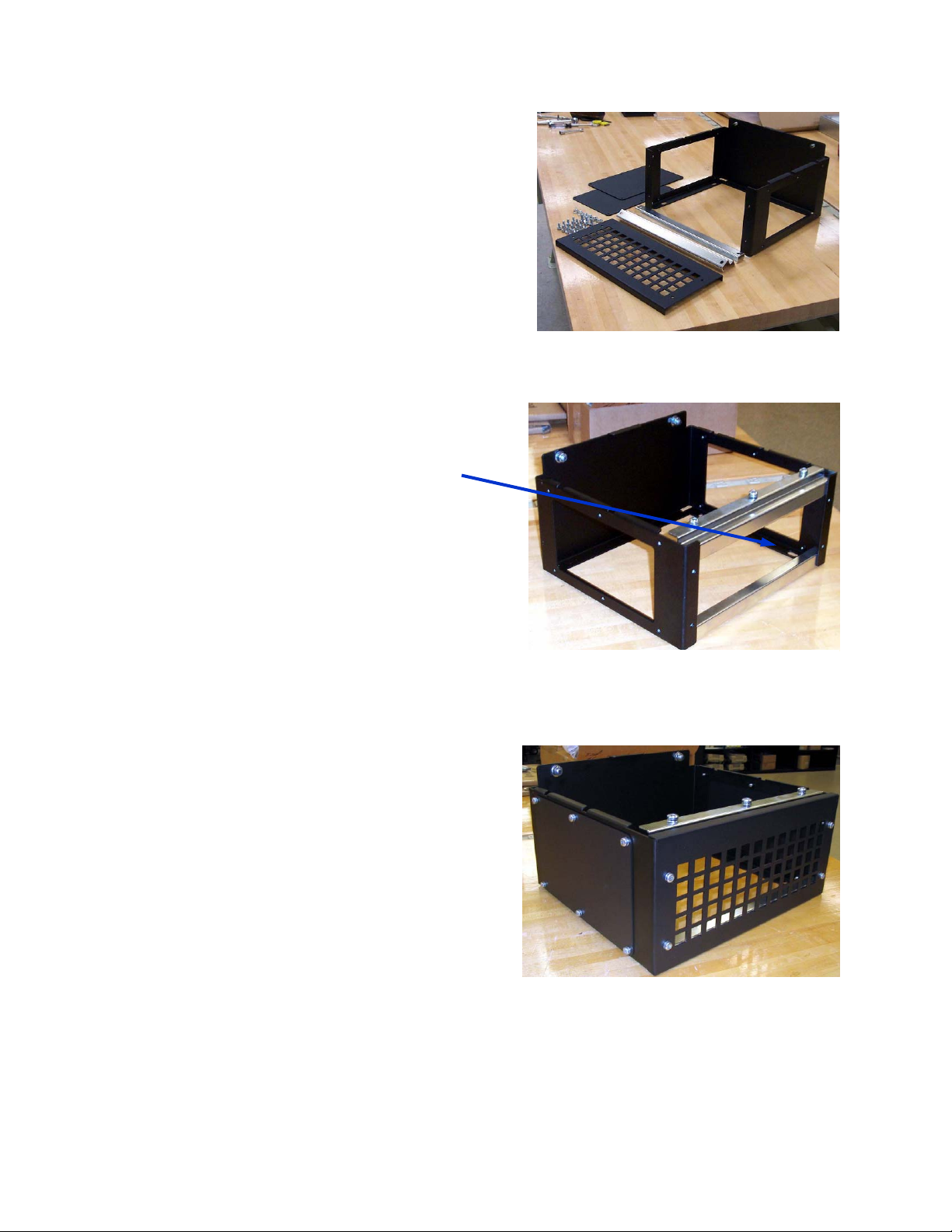
The kit contains the primary pedestal frame, a
vented front cover, 2– side covers, two front
brackets and the required hardware for assembly.
Shown in Photo 2 is a partially assembled
pedestal. Before installing the drive on to
the pedestal, the pedestal must be anchored
to the floor using the four pedestal mounting
holes. The holes can accommodate up to
M12 bolts (not included in kit)
CAUTION: The drives are top heavy and
may fall over if the pedestal is not anchored
to the floor.
The entire assembly may also be supported
by using the drive top mounting holes to anchor to a wall structure.
Photo 1. Pedestal Parts
Photo 2. Partially assembled pedestal
The completely assembled pedestal with
vented front cover and two side covers installed is shown in Photo 3. Multiple drives
may be mounted side-by-side. The interior
side plates are left off when installing drives
side-by-side.
Note: The front and side cover mounting
screws are recessed M6 Torx socket flat
head screws.
Photo 3. Completely assembled
pedestal
177Rxxxx 12/2009 DET-721, Page 2
Page 3

Install drive by lowering it on to the pedestal. The drive must
initially overhang the front of the pedestal to clear the retaining bracket on the rear of the pedestal. After the drive is on
the pedestal, slide the drive to the rear until the slot in the
drive engages the retaining bracket on the pedestal.
Slot
Retaining
bracket
Retaining
bracket
177Rxxxx 12/2009 DET-721, Page 3
Secure the back of
drive with two M10
nuts
Secure the front of the drive to the
pedestal with three M8 screws.
 Loading...