

Page 1
OKCV3000CN
DeviceNet.
INS
GE
Motors&Industrial
TRUC
TIONS
Systems
Page 2

Page 3
DeviceNet.
Instruction
Manual
Page 4
All
rights
reserved
Revision
Version
These
gencytobe
lems
Industrial
This
solely
This
the
History
instructionsdonot
arise
Systems.
document
to assist that
document
written
Data
met
during
installation,
that
are
not
covered
contains
customerinthe
shall
notbereproducedinwholeorin
approvalofGE
Note
purporttocover
operation,
sufficiently for
proprietay
Motors&Industrial
informationofGeneral
installation,
all
detailsorvariations in
and
maintenance,iffurther
the purchaser’s
Electric
testing,
Systems.
operation,
part
nor
equipment,
purpose,
Company,
and/or
shall
its
contentsbedisclosedtoany
nortoprovide
informationisdesiredorif
the
matter
shouldbereferredtoGE
USA
andisfurnishedtoits
maintenanceofthe
eve,’,’
possible
particular
equipment
third
described.
party
contin
-
prob
-
Motors
customer
&
without
Page 5
1.
INTRODUCTION
1.1.
ABOUT
1.2.
ASSUMPTION
1.3.
TERMINOLOGY
1.4.
MAIN
1.5.
MAIN
1.6.
WHATYOU
1.7.
HARDWARE
2.
CONFIGURATION
THIS
MANUAL
1.3.1....
1.3.2.
about DeviceNet
...
about
FEATURESOFDEVICENET
FEATURESOFDGFC
CAN
CONFIGURATION
ABOUT
YOU
DGFC
DO
PARAMETERS
DeviceNet
INDEX
1
1
1
1
2
3
3
4
4
1
3.
HOW
TO
CONNECT
CONNECTION
3.1.
GENERAL
3.2.
USER
GUIDE
3.2.1. Example
3.3.
HOWTOMANAGE
4.
HOW
TO
4.1.
GENERAL
4.2.
SERVICES
CONFIGURE
4.2.1.
4.2.2.
4.2.3.
4.2.4.
DGFC
SET)
AS A
DESCRIPTION
OGEC
WITH
DESCRIPTION
AVAILABLE
Fixed
Word sen’ices
4.2.1.1.
4.2.1.2.
4.2.1.3.
4.2.1.4.
Single
4.2.2.1.
4.2.2.2.
Multi;ole
4.2.3.1.
4.2.3.2.
Consideration
FixedWordArea
FixedWordArea
FixedWordArea Get_Member service
FixedWordArea
Parameter services
Single
Single
Parameters
Multiple
Multiple
about
AS
SLAVE
SLAVE-ONLY
STATE
OFAPLC
COMMUNICATION
DEVICENET
Get_Attribute
Set_Attribute_Single
Set_Member
Parameter
Parameter
seivices
Parameters
Parameters
the
Get_Attribute_Single
Set_Attribute
Get_Mult_Parm service
Set_Mult_Parm
encoding
examples
(PREDEFINED
Single service
service
service
service
Single service
service
MASTER/SLAVE
CARD
1
1
1
2
4
1
1
1
1
2
2
3
4
5
5
7
8
9
10
11
@
5.
LOCALBUS:
5.1. MASTER/SLAVE
5.2.
CONNECTING
HOW
TO
EXCHANGE
CONVERSATIONS
TOGETHER
DEVICENET
I/O
DATA
CARDS
INDEX
1
1
1
Page 6
5.3.
HOW
DEVICENET BRICKS
5.4.
FLOWOFDATA
5.5.
FLOWOFDATA
5.6.
CFlX:FIXED
5.7. RFIX:
5.8.
WFIX:
5.9. EXAMPLEOFBRICKS
5.10.
LOCALBUS:
6.
HOW
TO
CONNECTION
6.1.
GENERAL
6.2.
USER
7.
LOCALBUS
SOME
CONSIDERATIONS
WORD
READ
FIXED
WRITE
CONNECT
SET)
DESCRIPTION
GUIDE
AND
ACT
FROM
FROM
FIXED
WHATTODOTO
CLIENTTOSERVER
SERVERTOCLIENT
COMMUNICATION
WORD
WORD
PROGRAM
USE
IT
DGFC
AND
AS
SLAVE
EXECUTEABRICKS
PREDEFINED MODE
GEl-
100343
OFAPLC
(PREDEFINED
PROGRAM
SIMULTANEOUSLY:
2
3
3
4
5
6
7
8
MASTER/SLAVE
1
1
1
1
8.
DEVICENET
APPENDIXA-DEVICENET
APPENDIXB-DEVICENET
APPENDIX
APPENDIXD-CONSIDERATION
ERROR
C—CAN
CHANNELS
Typeofconnection
Typeofcable
Terminating
DeviceNet
DeviceTap
Power
Length
Grounding
Configuring
Howtoconfigure
Power
Single-supply,
Single
Load
To
avoid
Hardware
HANDLING
DATA
ERROR
ABOUT
resistor
Connector
Tap
Network
the
configurations
End-connected
Supply
limits
Center-Connected
errors
TYPES
TYPES
Power
power
CABLE
AND
POWER
1
1
1
1
1
1
1
1
1
2
2
3
3
4
5
5
6
7
8
8
II
INDEX
Page 7
1.1.
ABOUT
THIS
DeviceNet
INTRODUCTION
MANUAL
This manual describes
-
how
DGFCs
-
how
the DGFC
-
how the
1.2.
ASSUMPTION
We
assume
If
you want to use LocalBus, Bricks and
1.3.
1.3.1.
DeviceNet:
CAN:
MACID:
Duplicate MACID
Bus
Off:
Object:
Attribute/Service:
Object modeling(or
Predefined
Client:
Server:
DGFC
that
TERMINOLOGY
...
master/slave
DeviceNet
can
be connected
canbeconfigured
canbeconnectedtoa
ABOUT
you
already
about
Check:
knows
DeviceNet
profile):
connection
features ofthe DGF card
together,
without the need of any other node (LocalBus);
(Explicit
PLC
Messages);
(Predefined
(DGFC)C:
Master/Slave
Connection
Set,orPredefined
YOU
DGFC hardware and DBASE informations.
Win+Drive
is a serial protocol, object
the ControllerArea Networkisa
1)aMedia
2)
Physical
CAN
whichitresides, or the Application
Methods for making physical
CAN
the Media
isaspecial
another to place itself
whenanabnormal
isanabstract
in first approximation,we can say they are the visible data and
dure ofan object;
isasetofobjects
set:
is
a subset of DeviceNet
is
the
is
the node that reacts to the
tools knowledgeisalso required.
oriented,
Access
signaling;
does
not specify
signaling
Access
check that
node that
Control
are
definedbyDeviceNet specifications.
Control IDentifier is the address;
rateoferror
representation ofacomponent
that describes how a
originates
(MAC)
the
entire
connections,
does
notallowanode
on-line;
occurs
rules
(only
the transmission
transmission.
CAN based;
communication
methodology;
Physical
Layer
Layer
protocol
providing
with
theCANchip
present
device
one
master
The Server’s reaction may
acts;
Mode)
protocol. It defines:
and/or Medium upon
used to move
power,
the same MACID of
places
itself
in a device;
allowed);
data.
applying
off-line;
proce
-
cause it to
return
INTRODUCTION
a message to the Client.
Kiln
Page 8
GEl-
100343
1.3.2.
Bricks:
DGFC
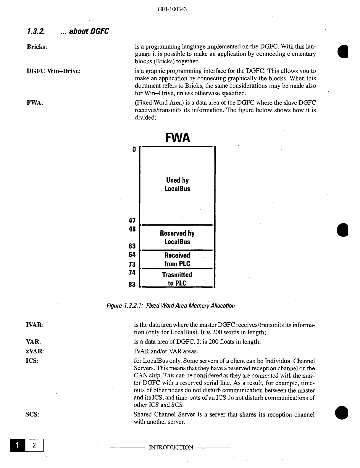
FWA:
about
Win+Drive:
DGFC
isaprogramming language
guage itispossibletomake an
blocks
isagraphic programming
makeanapplicationbyconnecting
document
for
(Fixed
receives/transmits
divided:
(Bricks) together.
refers
toBricks, the same considerations may be made also
Win+Drive, unless otherwise
Word Area)
is a data area of the DGFC
its information.
implementedonthe DGFC.
interface
FWA
0
Used
by
LocalBus
With
this
lan
applicationbyconnecting elementary
for the DGFC. This allows you to
graphically
specified.
The
figure
the blocks. When this
where
the
slave DGFC
below
shows how it is
-
0
WAR:
VAR:
xVAR:
ICS:
SCS:
Figure
47
48
63
64
73
74
83
1.3.2.1:
is thedata area where themaster
tion
isadata area of
IVAR and/or
for
Servers.
CAN
ter DGFC
outs of other nodesdonot
and
other
Shared
with another
Reserved
by
LocalBus
Received
from
PLC
Trasmitted
to
PLC
Fixed
Word
Area
Memory
(only
for
LocalBus).
DGFC.
VAR
areas.
LocalBus
chip. This
its
ICS
only.
Some
This
means
that they have a reserved
can
beconsideredasthey
withareserved
ICS, and time-outs of an
and
SCS
Channel
Server is a server that shares its
server.
Allocation
DGFC
It is 200
It is 200
serversofa
serial
disturb
ICSdonotdisturb communications of
receives/transmits
words
in length;
floatsinlength;
clientcan be Individual Channel
reception
are
connected
line.
As a result,
communication between the master
for
its
channelonthe
with
example,
reception
informa
the
mas
time
channel
0
-
-
-
0
MIlE
INTRODUCTION
Page 9
1.4.
MAIN
FEATURES
OF
DeviceNet
DEVICENET
These are the main features of
-
upto64nodes;
-
3 selectablebaud rates:
-
linear
topology;
-
distances
between
first
DeviceNet:
500,
and last node:
500 meters (1640
250 meters
100
meters
-
duplicateMACID
-
trunk/drop line
-
trunk lineisthe backbone
-
drop lineisthe cable that
-
maximum drop line length is 6
-
cumulative
-
trunk lineisterminatedby120-ohms
-
shielded doubletwisted pair (power
-
cable is5wires: 2 for
-
miswiring protection;
-
multimaster
-
peer-to-peer;
-
node removal
-
CAN technology
-
supports
-
supports
drop
156
meters
78
meters
39
meters
capabilities;
isolated and non-isolated nodes;
self-powered and network-powered nodes
(820
(328
detection;
cable;
line length
(512
(256
(128
without
(built-in
ft.)@250
ft.)@500 kbaud
(main
“hangs”
ft.)@125
ft.)@250 kbaud
ft.)@500 kbaud
power,
severing
errormanagementasCRC,
250 and
ft.)@125
line)
from the
meters;
is:
2 for
signal,1for
the network;
125
kbaud;
kbaud
kbaud
ofthe cable
trunk
line and
kbaud
resistorsonboth
+signal);
shield
system;
connects
ends;
stuff,
form,
(simultaneously);
devices
etc.
and
to the trunk line;
Bus
Off);
1.5.
MAIN
These
are the main
1-support
eters in
FEATURES
DGFC
of the Predefined Master/slave connection
reading
and10in writing with the master (usually a PLC, butaPC card
this case the cardisslave
only
card, the secondto
2-support
another
of a LocalBus. By
DGFC (peer-to-peer), without
haveupto3masters and many
OF
THE—DGFC
DeviceNet
only.
features.
There are two
useaDGFCasa
using
some
slavesatthe same
sub-modes.
communication
DeviceNet
using
any other node (no
time.
INTRODUCTION
set.
This allows the exchangeupto10drive
can
also be
The first is to useaDGFC
card and executeaBricks
Bricks (or
W-f-D
blocks) you
PLC/PC
required).
program
can
Note that each node
param
connected).
In
as a communication
simultaneously.
connectaDGFC to
can
LiEU
-
Page 10
‘.~J1iA~IUU~J~-t~)
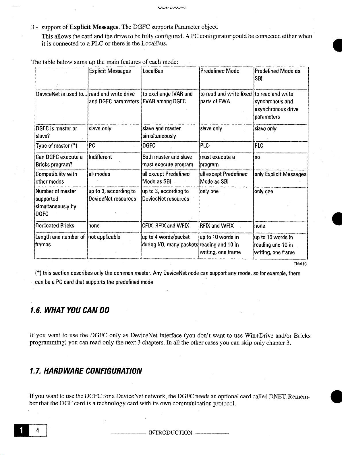
3-support of
This allows the card
it is connected to aPLCorthereisthe LocalBus.
The table below sums up the main features of each
DeviceNet is
DGFC
is master
slave?
Typeofmaster
Can DGFC
Bricks
program?
Compatibility
other
modes
Numberofmaster
supported
simultaneously
DGFC
Explicit
used
to...
or
(1
execute
a
with
by
Messages.
and
the drive to befully
Explicit
read
and
slave
PC
Indifferent
all
up
DeviceNet
Messages
and
write
DGFC
only
modes
to 3,
according
parameters
resources
The
drive
DGFC
to
supports
configured.
LocalBus
to
exchange
FVAR
slave
and
simultaneously
DGFC
Both
master
must
execute
all
except
ModeasSBI
upto3,
DeviceNet resources
Parameter object.
mode:
IVAR
among
DGFC
master
and
program
Predefined
according
A PC configurator couldbe connected either
and
slave
to
Predefined
to
read
partsofFWA
slave
PLC PLC
must
program
all
except
ModeasSBI
only
Mode
and
write
only
execute
Predefined
one
a
Predefined
SBI
fixed
to
read
synchronous
asynchronous drive
parameters
slave
only
no
only
Explicit Messages
only
one
and
Mode
write
when
6
as
and
Dedicated
Length
frames
(*)
this
canbeaPCcard
1.6.
If
you want to
programming) you
1.1.
Bricks
and
number
section
WHAT
describes only
YOU
use
none
of
not
applicable
the
common
that
supports
CAN
the DGFC onlyasDeviceNet interface
can
the
predefined
DO
read
only the next3chapters.Inall
HARDWARE CONFIGURATION
CFIX, RFIX
upto4
during
master.
Any
mode
and
WFIX
words/packet
I/O,
many
packets
DeviceNet
(you
the
node
other
RFIX
and
WFIX
upto10
reading
writing,
can
don’t
words
in
and10in
one
frame
support
cases
any
want to use Win+Drive and/or Bricks
you
can
none
upto10
reading
writing,
mode,sofor example,
skip only chapter
words
and
one
in
lOin
frame
TNetlO
there
3.
If
you want to use the DGFC
ber that the DGF cardisa
Eli
foraDeviceNet network, the DGFC
technology
card
with
its
own
commuhication
INTRODUCTION
needsanoptional
protocol.
card
called
DNET.
Remem
-
0
Page 11
DeviceNet
2.
CONFIGURATION PARAMETERS
There are various parameters which are used to initialize and configurethe
Parameters
From
parameters
The parameters
400-DNetEnable:
Enable/disable
0=Disable
1=Enable
2=Enable
Default
401-DNetStatus:
Status of DeviceNet communications. The DeviceNet softwarewrites a
0 meansnoerror.
402-DNetStAux:
Contains an
aredivided in3“blocks”.
parameter
value=0
420 to 429
for
Predefined
are:
DeviceNet
DeviceNet communications
DeviceNet communications
DeviceNet communications
(disable).
See
auxiliary
mode.
communications.
appendixBfor errortypes.
status
From
parameter 400 to 419 there are
there
are
parameters
You
can
load
This
(LocalBusorPredefined
(LocalBus
codeifnecessary.
for
LocalBus
parameter
parameterisanalyzed
The
and
Predefined
value 0
default
meansnoerror.
communication.
values
Mode)
in the blocks you don’tuse.
at power-on
Mode
status
DeviceNet software.
general
simultaneously)
See
parameters.
From
only.
code to
this
appendixBfor
430 to 439
parameter.
there
The
error types.
are
value
403-DNetStUser:
Contains an
404-DNetMacld:
Defines the node
Default
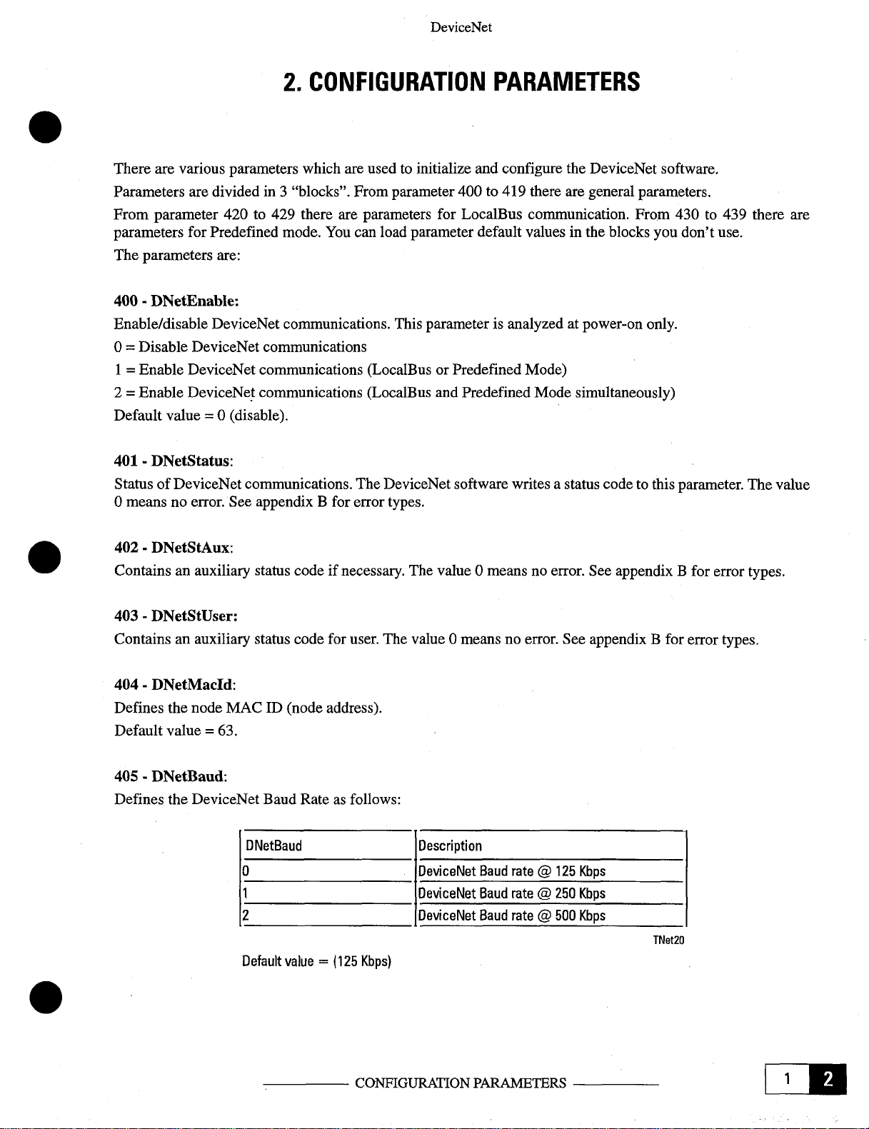
405-DNetBaud:
Defines the DeviceNet Baud Rateasfollows:
auxiliary
MACID(node
value=63.
status
code for
address).
user.
The
ONetBaud
0
1
2
Default value
=
(125
Kbps)
value 0
meansnoerror.
Description
DeviceNet
DeviceNet
DeviceNet
Baud
Baud
Baud
See
rate @
125
rate@250
rate @
500
appendixBfor
Kbps
Kbps
Kbps
TNet2O
error types.
CONFIGURATION
PARAMETERS
LIZE
Page 12
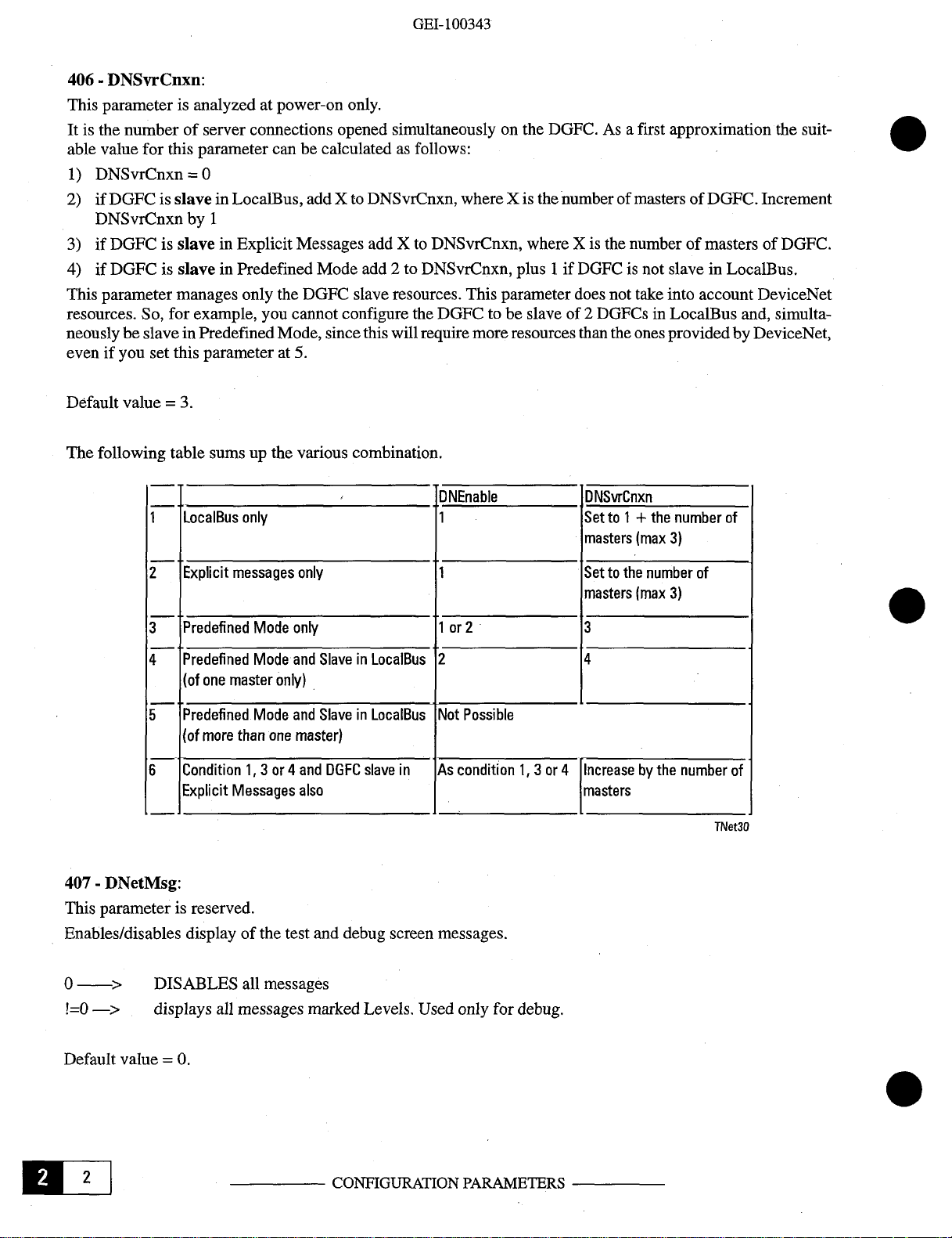
406-DNSvrCnxn:
This
parameter
It
is the
numberofserver
able
value
1)
DNSvrCnxn=0
2)ifDGFC is
DNSvrCnxnby1
3)ifDGFC is
4)ifDGFC is
This
parameter
resources. So,
neously
evenifyou set
be slavein
is analyzed at power-on
for
this
slaveinLocalBus,
slaveinExplicit
slaveinPredefined
manages
for
this
GEl-
100343
only.
connections opened simultaneouslyonthe
parameter
example, you cannot configure the DGFC to be slave of 2
Predefined
parameterat5.
can be calculatedasfollows:
addXto DNSvrCnxn,
Messages addXto DNSvrCnxn, where X is the number of masters of
Mode add 2 to DNSvrCnxn, plus1if
only the DGFC slave
Mode, sincethis
resources.
will
where
This
requiremoreresourcesthan the
DGFC.Asa first approximation the
Xis
thenumber of
parameter
DGFC
does
mastersofDGFC.
is not slave in LocalBus.
not take
DGFCs
into
account DeviceNet
in LocalBus and,
ones
provided by DeviceNet,
suit
Increment
DGFC.
simulta
-
-
Default
The
following
value=3.
table
1
2
3
4
5
6
sumsupthe
LocalBus
Explicit
Predeflned
Predefined
(of
Predelined
~of
Condition
Explicit
only
messages
one
master
more
than
Messages
1, 3or4
Mode
Mode
only)
Mode
one
various
combination.
only
only
and
SlaveinLocalBus
and
SlaveinLocalBus
master)
and
DGFC
slave
also
ONEnable DNSvrCnxn
1
Setto1+the
masters
1
Settothe
masters
1or2 3
2 4
Not Possible
in
As
condition
1, 3or4
Increasebythe
masters
number
(max
3)
number
(max
3)
of
of
number of
TNet3Q
407-DNetMsg:
This
Enables/disables
0
‘=0—>
Default
Hill
parameterisreserved.
display of the test anddebug
>
DISABLES
displays
value=0.
all
messages marked
all
messages
screen
Levels.
CONFIGURATION
messages.
Used only
for
debug.
PARAMETERS
Page 13
420-DNetIIOEpr:
Expected
different from0,otherwise time-out errors
specifications,
packet
this valueis
rate
for
110
connections.
internally multipliedby4. Used
DeviceNet
According to
will
not be reported. It is expressed in msec. According to DeviceNet
DeviceNet
only
for LocalBus.
specifications you
must
set here a
value
Default
421-SlaveMapLow:
Bit mapped double word
server
422-SlaveMapiligh:
Bit
server
430
Valid
DGFC from the
not executed (see
431-DN#TxPLC:
Valid
DGFC to the
executed (see relative
value=0
is enabled. Used only
mapped
is enabled. Used only
-
DN#RxPLC:
only for “Predefined
only for “Predefined Master/Slave
ins.
for
double word for slave_id32to
master.
master.
Must be set when a Bricks program is executed.
relative
chapters).
Must be set when a Bricksprogram is executed.
chapters).
slave_id
for
for
Master/Slave
0 to
31.Ifa bitisset to1,the communication with the
LocalBus.
63.Ifa
LocalBus.
Connection Set”
This
parameterisanalyzed
Connection
This parameterisanalyzed
bitisset to1,the communication with
Set”
(PLC).
(PLC).
Thisisthe number of bytes received by the
It’s
calculated
at power-on
Thisisthenumber of bytes transmittedby the
It’s
at power-on
only.
calculated when Bricksprogram isnot
only.
when Bricks
corresponding
the
corresponding
program
is
CONFIGURATION PARAMETERS
Liz.
Page 14

Page 15
3.
HOWTO
CONNECT
THE
uevicei~
et
DGFCAS
SLAVE
OFA
PLC
(PREDEFINED
AS A
3.1.
GENERAL
This kind of
With
this connectionsnoBricks program execution is
card. LocalBus is not
or
Bricks).
keypad orbyaPCconfiguration
not
all
parameters
3.2.
USER
In
order
to use this
DESCRIPTION
connectionismade with many slaves and one and only one
supported
The
configuration
canbeexchanged
GUIDE
feature
SLAVE
of thismode is made
ofthe
MASTER/SLAVE
in this case. Note that touse
program
through this type of
DGFC,dothe
CONNECTION
ONLY
(e.g.
COMMUNICATION
master,
allowed.
only
throughparametersthat
HIBS)connected tothe DGFCbytheR5485
following:
The
this
feature
connection.
DGFC
you
acts
don’t
SET)
CARD
usuallyaPLC
onlyasa slave
need any
can
be input either by thedrive
(or
communication
tools(Win+Drive
serial
line. Notethat
PC)
card.
1)onthe DGFC
-
disconnect the cardfrom the DeviceNet
-
transition the DGFC to IDLE
-
load
default
-
set
parameter
-
set
the
-
set
the
-
set
parameter
-
set
parameter
-
set
DPRAM
the number of
nous parameters arein thetop of parameters read/writtenbyPLC, while
bottom of parameters
-
parameters
on.
Be sure that the
master
-
set
parameter
-
save parameters of the
2)onmaster node: (Remember that for
-
configure the
-
configure
card
parameters
350 of the
appropriate
appropriate
“DN#RxPLC”
the
MACIDinthe “DnetMacld”
baudrate in the “DnetBaud”
501
ofthe DGFC (“period
504 of the DGFC
configuration parameters
parameters
read/writtenbyPLC
values
400 of the DGFC
DGFC
DGFCasa
proper
number of
network
state
DGFC (DGFC
(“ab.
to read/write is obtained from
and “DN#TxPLC”
of these parameters match the number of
(“DnetEnable”)to1
Polled device
bytes
mode)to10
parameter
parameter
tim”)
to 2
RUN”) to 0
to the
values
will
be automatically calculatedbythe DGFC at
parameter
transmitted/receivedbythe PLC
configurationyou mustuse PLC
(MACID
(baud
of drive
DPRAM
must be
rate must be the same in the network)
parameter
configuration parameters.
unique
indexes
asynchronous
bytes
transmitted/ receivedbythe
in the
network)
to read/write. Remember:
parameters
software)
The
synchro
arein the
next
-
power
HOW CONNECT
THE DGFC
Li’.
Page 16
3)
connect the DGFC to the
ATTENTION:
ATTENTION:
ATTENTION:
DeviceNet
maximum
maximum
network, power off and thenonthe
number
number
of parameters readis10
of parameters
writtenis10
before starting be surethat the number of
on
the DGFC and
master.
Otherwise
unpredictable
parameters
system
received
behavior
and
can
transmitted
occur.
matches
3.2.1.
Note: Remember that at the
(8192 decimal).
number
(TE)
(El)
eter
-
Example
number
For
example, the
39)is8231
communication
communication
of the
drive,
decimal
and
(8192+39) or in hexadecimal
the
parameterisexchanged from the
from
the
drive
ASYN
for
set DPRAM configuration parametersasfollows:
par
lOOIESYNO
par
101
JESYN1@8695
par
l2OIEASYNO
par
121
JEASYN1@8507
par 1221E
par
ilOEISYNO
ASYN2
parillEISYNi
par1I2EISYN2
par
140E1
par 141
par
142
par
143
par
144ElASYN4
ASYNO
EIASYNl
EIASYN2@
EIASYN3
@8230
@8506
@8247
@8200
@8201
@8289
@8314
@8305
8302
@8248
@8572
of the drive
number
to the
that you must use forTcurrent
DGFC.
those parameters identified
parameter
SYN
(Ramp ref1parameter
(Pad
(Enable
must be
sum
of the
ref
202711
DGFC
(2000H
+2711).
to the drive
(synchronous parameter)
with
the
symbol*in the
number
0 parameter number
drive parameter
number
1 (torque set point has
503)
(Start/stop parameternumber 315)
(Control
(T current lim+parameter
(Tcurrent
(Enc1position parameter
(Actual Speed parameter
(Ramp
(Ramp ref [rpm]parameter
(Status
(Drive ready parameter
word parameter
lim-
parameter
outp
[rpm]parameter
Word
parameter
number
number
number
number
number
number
number
number
parameter
During
and
during
is used
drive
44)
314)
number
56)
380)
number +2000Hex
Internal-to-External
External-to-Internal
for
high
priority
parameter
55)
8)
9)
197)
122)
113)
110)
parameter
param
tables.
-
This
means
-
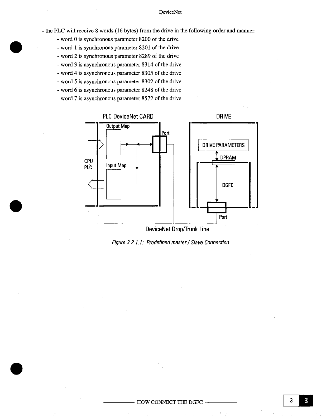
the PLC
mlii’
that:
will
transmit5words
-
word 0 is synchronous
-
word1is
-
word 2 is asynchronous
-
word3is asynchronous
-
word 4 is
synchronousparameter
asynchronousparameter
(iQ
bytes)
parameter
parameter
parameter
to the drive in the
8230
of the drive
8695
of the drive
8506
of the drive
8507
ofthe drive
8247
ofthe drive
HOW CONNECT
following
THE
DGFC
order
and
manner:
Page 17
-
the PLC will receive8words
-
word 0 is
-
word1is
-
word 2 is
-
word3is
-
word 4 is
-
word5is
-
word 6 is
-
word 7 is
synchronous
synchronous
synchronous
asynchronous
asynchronous
asynchronous
asynchronous
asynchronous
DeviceNet
(i~
bytes) from the drive in the following order and
parameter
parameter
parameter
parameter
parameter
parameter
parameter
parameter
8200
8201
8289
8314
8305
8302
8248
8572
of the drive
of the drive
of the drive
of the drive
of the drive
of the drive
of the drive
of the drive
manner:
PLC
DeviceNet
Figure
CARD
DeviceNet
3.2.1.1:Prede
Drop/Trunk
Line
fined master/Slave
DRIVE
Connection
HOW CONNECT
THE DGFC
LZ
Page 18
32.
HOW
TO
MANAGE
DGFC
STATE
GEl-
100343
The
DGFC
RUN
transition
When mode10is selected
automatically
when
The
ALARM
is not able to
when the card is in
To
reset
1)
connect
output to be
2)
connect
input
The master program
the slave is active to be sure
the DGFC and
tween the DGFC and
(“Opt2
This is only one of several
priate
Also, you can
avoid the use of the TBO card.
basically
state
the
program
to RUN state. DGFC transitionstoALARM
managed by the DGFC.
the
communication
stateneeds the intervention ofanexternal source in orderto
reset
the DGFC
iphysical
iphysical
to be
failure”atlow level), it
keyonthe drive
use
has4states:
that
the
drive
RUN
ALARM
digital
“Opt2
failure”;
digital
“Failure
master
the
Reset”;
must
drive
keypad
“OK
writes/reads the drive parameters is
(refer
with
state.)
check
that
occurs even in the ALARM state, but in the
possible
relay”
IDLE,
READY,
to the DGF
With
the master falls.
while itisin ALARM itself.
state:
input
of the master toadigital output
output of the master to a
that
the “Opt2 failure” inputis atahigh level and
received/transmitted
is not active).
must
reset
the
methods.
(usually this is labeledas“CANC”)
instead of the digital
RUN
and
ALARM.InIDLE
state
when amalfunction occurs.
manual, GEI-100339),
mode10selected,
(Parameters
digital
values are
When the
DGFCbysetting
You can,
master
for
example,
output.
state
executed.InREADY
the IDLE,
the ALARM state is
be.
are
of the drive.
input of the drive.
consistent
ALARM
detects
the
Using
that the
“Failure
reset
the
insteadofusing
the
keypad
READY
exited. Thisisbecausethe DGFC
exchanged
(note
thatcommunication
DGFC
Reset” output.
alarm
the
cardisconfigured.
state
the
DGFCisready
and
RUN states
presentonthe
with the drive only
Configure
Configure
that
the
communication
state
communicationbe-
is in the
through
and
pressing
the
“Failure Reset”
the “OK relay” you can
DGFC
this drive digital
this drive digital
ALARM
between
the
appro
input.
In
to
are
only
with
state
6
-
0
•iii:
HOW CONNECT
THE
0
DGFC
Page 19
4.
HOW
4.1.
GENERAL
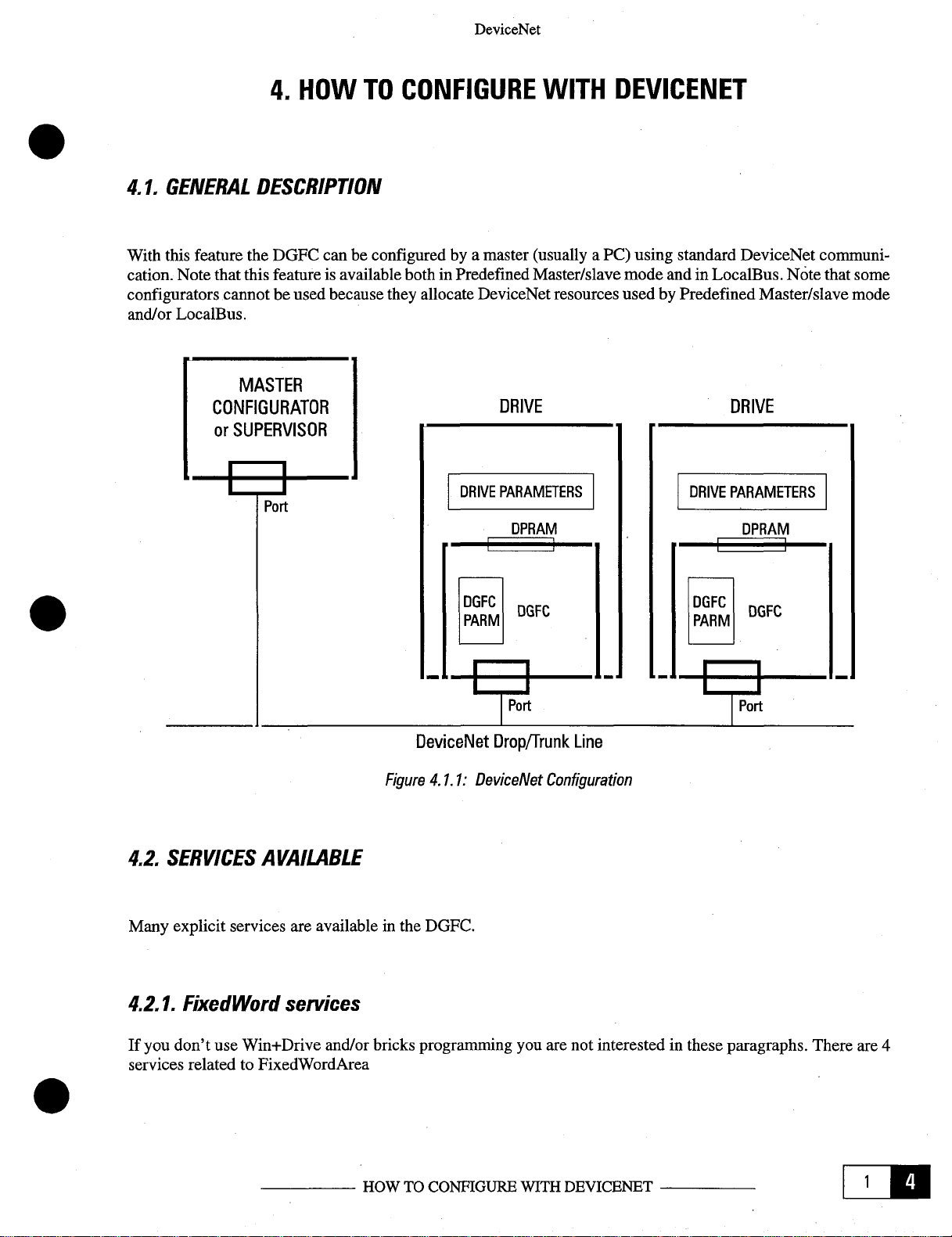
With
this feature the DGFC canbe configuredbya master
cation. Note
configurators cannot be used
and/or
LocalBus.
DESCRIPTION
thatthis
featureis availableboth in PredefinedMaster/slave
TO
because
CONFIGURE
they
allocate
DeviceNet
(usually
DeviceNet
WITH
resources usedbyPredefinedMaster/slave
DEVICENET
a PC)
using
standard DeviceNet
mode
and in
LocalBus.
Notethat
DRIVE
communi
some
mode
-
4.2. SERVICESAVAILABLE
Many
explicit
4.2.1.
If
you don’t
services
services
Fixed Word
use
Win+Drive
related to Fixed
are
availableinthe
services
and/or
WordArea
HOWTOCONFIGURE
bricks programmingyou are not
DeviceNet
Figure
DGFC.
4.1.1:
Drop/Trunk
DeviceNet
Configuration
WITH
Line
interested
DEVICENET
in these paragraphs. There are 4
Li’.
Page 20
GEl-
100343
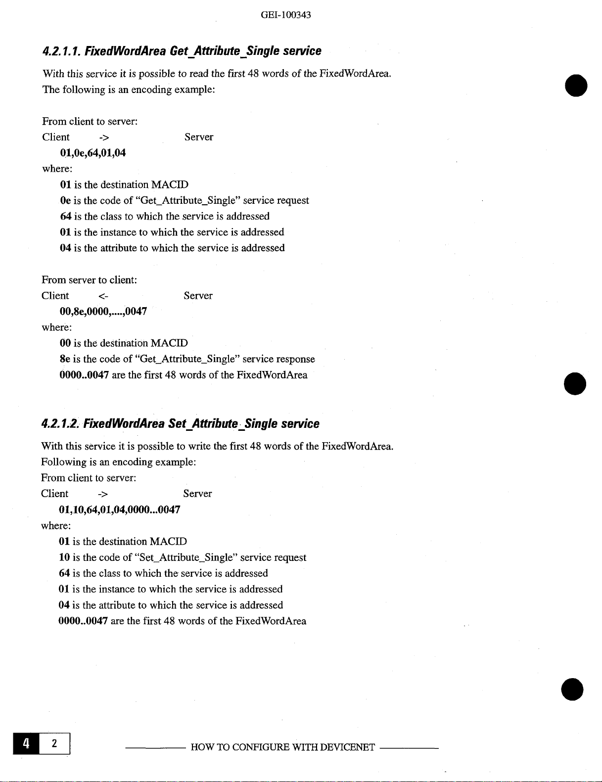
4.2.1.1. Fixed
With
this service it is possible to read the first48wordsofthe
The following isanencoding
From
client to server:
Client
WordA
->
rea
Get_Attribute
example:
Server
Single
01,Oe,64,O1,04
where:
01
is the destination
Oeisthe code of
64
is the class to which the service is addressed
01
is the instance to
04 is the attribute to which the service is addressed
From
server to client:
Client
00,8e,0000
where:
00isthe destination
8e is the code of
0000..0047 are the
MACID
“Get_Attribute....Single”
which
the service is addressed
Server
,0047
MACID
“Get_AttributeSingle”
first48words of the FixedWordArea
service
service
service
FixedWordArea.
request
response
4.2.1.2. Fixed
With this service it is possible to write the
Following isanencoding example:
From client
Client
WordA
to server:
->
rea
Set_Attribute
Server
01,10,64,01,04,0000...0047
where:
01
is the destination
10
is the code of
64
is the class to which the service is addressed
01
is the instance to
04
is the attribute to which the serviceisaddressed
0000..0047
are the
MACID
“Set_Attribute.Single”
which
the serviceisaddressed
first48words of the FixedWordArea
Single
first48words of the
service
service
request
FixedWordArea.
full
HOWTOCONFIGURE
WITH
DEVICENET
Page 21

From
server to
Client
00,90
where:
00
90
client:
is the
destination
is the code of
Server
MACID
“Set_AttributeSingle”
DeviceNet
service
response
4.2.1.3. Fixed
With
this
Following isanencoding example
From
client to
Client
01,18,64,01,04,OOle
where:
01
is the
18
is the code of
64
is the class to
01
is the
04
is the attribute to which the
001e is the
From
server to
Client
00,98,OOle,0000
where:
00
is the
OOle
98isthe
0000 is the word read
WordA
service
server:
->
destination
instancetowhich the service is
index
client:
destination
is the index of the word to read (first
codeof“Get_Member”
rea
Get
it is
possible
“Get_Member”
which
ofthe word to read (first
to read one or more words of the
Server
MACID
the
serviceisaddressed
Server
MACID
Member
for
service request
serviceisaddressed
service response
service
the protocol to read
addressed
FWA word:
FWA word:
FixedWordArea.
one
word:
index 0001)
index 0001)
Following isanencoding
From
client to
Client
01,18,64,01,04,801e,01,0004
where:
01
is the destination MACID
18
is the code of
64
is the
01isthe instancetowhich the service is
04
is the
801eisthe index of the word to read
01isthe Extended Protocol ID
0004 is the number of words to be
server:
->
class
to which the
attribute
example for the protocol to read twoormore
Server
“Get_Member”
serviceisaddressed
to which the service is
HOWTOCONFIGURE
service request
addressed
addressed
(tobeANDed
read
with
WITH
7fff)
(first
DEVICENET
consecutive
FWA word:
words:
index 0001)
EPA
Page 22

GEl-
100343
From server
Client
00,98,0004,OOle,0000..0003
where:
00isthe
98
0004isthe number of
OOle
0000....0003 are the words
4.2.1.4.
With
this
Following is an encoding
Fromclient
Client
01,19,64,01,04,OOle,0000
where:
01
19
64
01
04
OOle
0000
to client:
<-
destination
is the code of
is the index of the
Fixed
serviceitis possible to
to server:
->
is the destination
is the code of
is the classtowhich
is the instance to which the serviceisaddressed
is the attribute to
is the index of the
is the
“Get_Member”
WordA
“Set_Member~~
value
to be written
Server
MACID
members
first
rea
Set_Member
example
MACID
the service is
which
word
to be read
word
read
write
for
Server
service request
the service is
to write
service
read
response
(first
service
oneormore
the
protocol to write
addressed
addressed
(first
FWA
FWA
word:
words
word:
index
to the
FixedWordArea.
one
word:
index 0001)
0001)
Fromserver
Client
00,99
where:
00
is the destination
99isthe codeof“Set_Member”
Following isanencoding
From
client to server:
Client
O1,19,64,01,04,801e,01,0004,0000..0003
where:
01
is the destination
19
is the code of
64
is the class to which the serviceisaddressed
01isthe instance to which the serviceisaddressed
Hill
to client:
<-
->
Server
MACID
example
Server
MACID
“Set_Member”
HOWTOCONFIGURE
service
for
service request
response
the protocoltowrite
two
WITH
or more consecutive words:
DEVICENET
Page 23

04
is the attribute to which
801e
is the index of the word to read
01
is the
Extended
0004isthe number of
0000..0003 are the
From
server to
Client
00,99,0004,OOle
where:
00isthe
99
is the codeof“Set_Member”
0004isthe number of words written
001e is the index ofthe first word written (first
client:
destination
ProtocolID
values
words
to write
MACID
the
serviceisaddressed
to be written
Server
service
DeviceNet
(to
be ANDed with
response
FWA word:
7fff)
(first
index 0001)
FWA
word: index 0001)
4.2.2. Single
There
are
4.2.2.1.
With
this service itispossible:
-
to read the value of
-
to
read
-
to read the value of many attributesassociated with DGFC
Drive
parameters keep their own
DGFC
40001)
The possible attributes that
parameters have their own identifier
#1->value
#4->descriptor
#5->data type
#6->data
#7->parameter
#8->units
#10->minimum value
#11->maximum value
#12->default
Parameter
2 services related to
Single
Parameter
any
the value of any DGFC
size
name
string
string
value
services
Single
Parameter
Get_Attribute
drive
parameter
parameter
identifier.
can
be read
are:
Single
added
service
40000dec
with
parameters.
(parameter1of DGFC
must
be accessed
as
HOWTOCONFIGURE
WITH
DEVICENET
LilA
Page 24

GEl-
100343
Followingisan
To
read
the
valueofparameter
From
client to server:
Client
01,Oe,Of,8193dec,01
where:
01
Oe
Of
01
Fromserver
Client
00,8e,0000
where:
00
8e is the
0000 is the
typeofthe
->
is the destination
is the code of
is the class to which the serviceisaddressed (Parameter
is
the instance to
is the attribute to which the serviceisaddressed
to client:
<-
is the destination
codeof“Get_AttributeSingle”
encoding example:
MACID
“Get_AttributeSingle”
which
MACID
value
of the
read
parameter
read. The data
8193dC’
Server
Server
parameter.
of
the
the
drive:
service
serviceisaddressed
service
Important:
type
of the
request
(attribute:
response
this field can have any
parameter
class)
(parameter
to read must be known.
value)
8193
of drive)
length.
The length
0
dependsonthe
To
read
the
valueofparameter
From client to server:
Client
01,Oe,Of,40700dec,01
where:
01
Oe
Of
01
From
servertoclient:
Client
O0,8e,0000
where:
00
8eisthe
0000 is the
typeofdata
through
->
is the destination
is the
codeof“Get_AttributeSingle”
is the class to which the serviceisaddressed
is the instance to
is the attribute to which the serviceisaddressed (attribute:
is the destination
codeof“Get_AttributeSingle”
value
of the
attribute
MACID
MACID
ofthe
parameter
#5.
which
read
700dCC
of
DGFC:
Server
service
the
serviceisaddressed (parameter
Server
service
parameter.
read. The data type of the parameter to read must be
Important:
request
(Parameter
response
this field
class)
value)
can
700 of DGFC)
haveany
length.
Thelength
known
dependsonthe
or can be read
HIE
HOWTOCONFIGURE
WITH
DEVICENET
Page 25

To
read
the
attribute
From
client to
Client
Ol,Oe,Of,4O7OOdE~,O7
where:
01
Oe
Of
40700 is
07isthe
From
Client
O0,8e,Oa,20,69,76,61,72,20,30,20,20,20,20
where:
00isthe
8e
Oaisthe
20,69,76,61,72,20,30,20,20,20,20 is the ASCII
->
is the
destination
is the code of
is the
class
attribute to which the service is
server to
<-
destination
is the code of
length
#7 (Parameter name) of
server:
Server
MACID
“Get_Attribute....Single”
to which the serviceisaddressed (Parameter
the
instance
client:
of the
to which
MACID
“Get_AttributeSingle”
string
the
Server
associated.
parameter
servicerequest
service is
addressed
service
DeviceNet
700de’
ofthe
DGFC:
class)
addressed (parameter
(attribute:
response
string
that identifies the
parameter
700.ofDGFC)
name
string)
parameter
(“ivar
0”)
4.2.2.2.
With this
Drive parameters keep their own
DGFC
40001)
Followingisan
To
From
Client
where:
Single
serviceitis possible to write the value of any drive or
parameters
write the value of
client to
01isthe
10
is the code of
Of
is the
8193dec
01isthe attribute to which the
0000isthe value to be written.
data of the
Parameter
have their own identifier
encoding
parameter
server:
->
destination
“Set_AttributeSingle”
classtowhich the serviceisaddressed
is
the
instancetowhich
parameter
Set
example:
MACID
written. The data type of the
Attribute
identifier.
added
8193dC’
Server
of the
drive:
service request
the
serviceisaddressed (parameter
serviceisaddressed
Important:
this field can have any
Single
service
with
40000dec
(Parameter
(attribute:
parameter
DGFC
(parameter1of the DGFC mustbe
class)
parameters.
8193
of the
drive)
value)
len2th.
to write must be known.
Thelength
dependsonthe
accessed
type
as
of
HOWTOCONFIGURE
WITH
DEVICENET
[hA
Page 26

From
server to
Client
00,90
where:
00
is the destination MACID
90isthe
To
write the
From
client to server:
Client
where:
01isthe
10
is the
Ofisthe
40700d
01isthe attribute to which the service is addressed
0000
of the
attribute #5.
client:
Server
codeof“Set_AttributeSingle”
valueofparameter
->
destination MACID
codeof“Set_AttributeSingle”
class
to which the service is
is the
instance
is the
valuetowrite.
parametertowrite.
700dC
Server
to which the service is
Important: this field
The
typeofdata
of
DGFC:
addressed
GEl-
100343
service response
service request
(Parameter
addressed (parameter
(attribute:
can
have any
of the
parameter
class)
700 ofthe
value)
length.
to write mustbe
The
length dependsonthe
DGFC)
known
type
orcanberead
ofdata
through
From
server to
Client
00,90
where:
00
90isthe
4.2.3.
There
are
client:
is the destination MACID
codeof“Set_Attribute.Single”
Multiple
2 services related to Multiple
Parameters services
Server
service
Parameters.
response
Elm
HOWTOCONFIGURE
WITH
DEVICENET
Page 27

DeviceNet
4.2.3.1.
With
Driveparameters keep their own
DGFCparameters
40001)
Followingisan encoding
To
From
Client
where:
Multiple
this
serviceitis
read the
~
01isthe
4bisthe
65isthe class to
00isthe
8194dec
40700d~
valueofparameter
client to server:
->
destination
code of
instancetowhich the
is the 1st instance to whichthe
is the
is the 3rd instance to
is the 4th instance to
Parameters
possibletoread
have
their own identifieradded with
example:
MACID
“Get_Mult_Parm”
which
the
2nd
instancetowhich
Get
Mult
the
identifier.
8193d~
and
Server
serviceisaddressed
serviceisaddressed
which
which
Parm
valueof1ormore
8194~
service
the
the
request
serviceisaddressed
serviceisaddressed
the serviceisaddressed
serviceisaddressed
service
(maximum
40000d~
ofthe drive and
(parameter1of
(parameter
10)
driveorDGFC
7OO~~
and
8193
(parameter
(parameter
(parameter
8194ofdrive)
700 of DGFC)
701ofDGFC)
theDGFC
701dcc
of drive)
ofthe
parameters.
must
be accessed
DGFC:
as
From
servertoclient:
Client
00,cb,0000,00000000,0000,00000001,0000,00000002,0000,00000003
where:
00isthe
cbisthe
0000isthe
00000000 is the
of the
0000isthe
00000001isthe
of the
0000isthe result of the
00000002 is the
of the
0000isthe resultofthe
00000003isthe
of the read
<-
destination
codeof“Get_Mult_Parm”
result
read
parameter
result
read
parameter
read
parameter
parameter
MACID
of the
value
of the
value
value
value
Server
operationon1st
of the
1st
must be known.
operationon2nd parameter
ofthe
2nd
must be
of the 3rd read
must be
of the
must be
known.
operationon3rd parameter
known.
operationon4th
4th
known.
service
read parameter. Important: this field is always 4 bytes long. The
read
read
response
parameter
parameter. Important:
parameter. Important:
parameter
parameter. Important:
this
this field is always 4 bytes long. The data
this field is
fieldisalways
always
4 bytes
4 bytes
long.
long.
datatype
The data
The data
type
type
type
HOWTO
CONFIGURE
WITH
DEVICENET
LiE
Page 28

GEI-100343
4.2.3.2.
With
Drive parameters keep their
DGFC parameters
40001)
Followingisan encoding example:
To
From
Client
where:
Multiple
this
serviceitis possible to write the value of1or more
write
the
valueofparameter
client to
->
~ ,00000003
01
is the destination
4c is the code of
65
is the class to which
00
is the instance to
8193d
00000000 is the
of
8194dec
00000001 is the
type
40700dec
00000002isthe
typeofthe
40701d
00000003 is the value of the 4th written
of
is
the
written
is the 2nd instance to which the
of the written
is
is the instance to
the
written
Parameters
own
have
their
server:
MACID
“Set_Mult_Parm”
the
which
the
1st instance to
valueofthe 1stwritten
parameter
the
3rd
written
parameter
valueofthe
value
must
parameter
instance
of the 3rd
parameter
must
Set_Malt_Parm
identifier.
own
identifier
8193dec
Server
serviceisaddressed
the
service
which
be.
known.
2nd
written
must be known.
to which the
written
must be known.
which
the serviceisaddressed
be known.
added
and
8194dcc
service
the
request
is addressed
serviceisaddressed (parameter
parameter. Important:
serviceisaddressed (parameter
parameter.
serviceisaddressed (parameter
parameter. Important:
parameter. Important:
service
(maximumlO)
40000dec
with
of the drive and
this fieldis
Important:
(parameter
this field is
driveorDGFC parameters.
(parameter1of DGFC
700dec
and
701dec
8193ofthe
always
8194
of the drive)
this field is
this field is always 4 bytes long. The data
701
always
700 ofthe DGFC)
ofthe DGFC)
always
mustbeaccessed
of the DGFC:
drive)
4bytes
4 bytes
long.
The
4 bytes long. The data
long.
The data
as
datatype
type
Fromservertoclient:
Client
00,cc,0000,0000,0000,0000
where:
00 is the destination
cc is the code of
0000isthe result of the 1st writing operation
0000isthe
0000isthe result of the 3rd writing operation
0000isthe result of the 4th writing
flu
MACID
“Set_Mult_Parm”
resultofthe
Server
service
2nd
writing
operation
operation
HOWTOCONFIGURE
response
WITH
DEVICENET
Page 29

DeviceNet
4.2.4. Consideration
All
previous
All
previous
If
an error exists the server
Client Server
00,cc,00,ff
where:
00
ccisthe code of
00
ifisthe
The following table lists the Error Codes that may be
Response
02->Resource
08->Service
09->Invalid
GB->Alreadyinrequested
OC->Object
GE->Attribute not settable
OF->Privilege
1
G->Device
11->Reply data
13->Not enough data
14->Attribute not
15
16->Object
18->No stored attribute data
19->Store operation failure
iF->DGFC
20->
28->Invalid Member ID
29->Member not settable
encoding examples are supposed to be in
encoding
is the
destination
is the General Error Code
additional
message.
not
attribute
state
state
->Too
much data
does
specific
Invalid
parameter
about
examples
returns:
MACID
service
error
Unavailable
supported
value
conflict
violation
conflict
too
large
supported
not exist
error
the encoding
are
response
code
mode/state
examples
supposed not to generate an
hexadecimal
error.
present
in the General Error Code field ofanError
format.
HOWTOCONFIGURE
WITH
DEVICENET
LIlA
Page 30

Page 31

5.
5.1.
MASTER/SLAVE
LOCALBUS:
HOW
CONVERSATIONS
DeviceNet
TO
EXCHANGE
I/O
DATA
A “conversation”isthe execution of multiple transmissions and
the
DeviceNet
This kind of Brick
fies
which Master
which Slave words of
master).
The
Master
frame response fromthe Slave. The first word ofeach frame sentfrom
will
alwaysbea
sent
to the slave
in form of data
A
conversation may specify that
IVARs
associated with Fixed
The CODE word
5.2.
are to be sent to the
CONNECTING
serial network. All conversations
specifies
IVARs
always
initiatesaconversation
CODE word
device,informofdata
words).
specifies
which
are to be sent to the Slave
FWA
Word
the
TOGETHER
Slaveto communicate with and to executeconversations
are to be received from the
which
describes
words,
0, 1,
2 or3words of
Slave.
(s) can be
The
number
exchanged
of Fixed
DEVICENET
are
withaSlave.
the
construction
and which
Master
device
Words
executedbydedicated
(and
Slave
The last frame of any conversation must
FWA
sends
at every Bricks execution time of the
to be
CARDS
receptions
where to put the received words from the
(and where to put the received
ofthe conversation (which
FWA values
have to be received fromaSlave and
its
IVAR
received
betweenaMaster
communication
Master
from the
to Slaveorfrom Slave to Master
are
to be fetched from the slave
and
receives in
slave.
Bricks in the
FWA values
its
Master
andaSlave over
Master.
with.Italso
values
IVAR.
device.
speci
slave)
from
always
areto be
device,
0, 1,2or
The
values
-
and
the
be a
3
TheDGFCisableto communicate easily
cation
via
Bricks.
are:
-
the
DGFC
-
the DGFC
are
called
nel,
so they
Note that
The
other
TheSCS
goes
time-out
disconnection
The ICS
DeviceNet
ICS
server
channelsdonot
servers
off,
the first communication with this slave hasnoanswer and the device is
elapse. During
servers
Foreach DGFC cardthe
can
have3different
can
have63other
ICS
Server
are
called SCS
allows
communicate
ofthis
are the
“Individual Channel
Server
supports
powering
affect
device,
first
up to64devices.
these
using
this time, the communication
can the
seven
serversonBricks
DGFC
DGFC
off
the device without
communications.
the same
communication
with
other
DGFC
limitsontheother DGFCthat may be
masters
slaves.
“Shared
HOWTO EXCHANGE
The
Server”.
ChannelServer”.
channelofthe
program with different
Clients
first
slaves
All
influencing
with
the
with
the other Servers continue.
orServersbyprogramming
use an individual communication
other slaves use the same communication
the other communications; also errors
CAN
Controller
other
SCS
110
DATA
connected
chip. This
disconnected
serversisnot possible.
MACID
starting
with DeviceNet line
means
from
every
communi
channel
chan
thatifone slave
only after the
Only
afterthe
CFIX0block.
-
and
-
on
Page 32

5.3.
HOW
To
use the
-
there
-
the slave
-
the master
-
the master
-
during IDLE-to-READY,
-
during
in parameters
-
in
-
in
DEVICENET
DeviceNet
are
3 Bricks:
+
CFIXisthe Brickonthe master card
+
RFIX
reads/writes
reads/writes
acts
IDLE-to-READY, DeviceNet
READY
READY
Bricks
and
WFIX
as follows
“SlaveMapLow”
statenoBricks programisexecuted
state
DeviceNet
tain the I/O connections opened
-
during
-
in RUN state the
done (or
-
during
-
in
tain the
-
during
-
in IDLEnomaster
READY-to-RUN
scheduledifthe
RUN-to-READY
READY
state DeviceNet system
110
connections opened
READY-to-IDLE
Bricks
communication occurs
BRICKSACT
you must
in the
its own
CFIX
DeviceNet
program is executed.
transmitter
the pending
DeviceNet
remember
are
Bricksonthe slavecard
FWA;
IVAR
and
Bricks is analyzed and
system
and “SlaveMapHig”
system
software
(only
with connections
system
is busy), onlyifthe
transmissions
software
system
GEl-
100343
the
following:
decides
wheretowrite/read in the
some values
software
startstoestablish
transmits/receives
already
software
deletes
every
are
fixed
connections
some
meaningless wordsofFWAtomain
established)
meaningless
WhenaCFIXisexecuted, transmission
connection
are
deleted
transmits/receives
software
deletes
all
is established
some
meaningless
connections
slave-
with
transmission
words
still
open;
the slave mapped
still pending
over
the network
of FWA to
main
0
-
is
-
-
the slave
-
AUENT,oN:
actsasfollows
regardless ofthe DGFC state (IDLE/READY/RUN)
nection is
established
a
DGFC
can
be master and slave
DeviceNet
simultaneously.
system software answers to
master,ifcon
-
k2Z
:
:
HOWTOEXCHANGE
I/O
DATA
Page 33

5.4.
FLOW
OF
DATA
FROM
CLIENT
TO
DeviceNet
SERVER
5.5.
FLOW
OF
DATA
FROM
DeviceNet
Figure
5.4.1:
SERVER
TO
DROP/TRUNK
Data
Flow,
ClienttoSeiver
CLIENT
LINE
DeviceNet
Figure
5.5.1:
HOWTOEXCHANGE
DROP/TRUNK
Data
Flow,
Sen’er
110
DATA
LINE
to Client
LL
Page 34

5.6.
CFIX:HXED
SYMBOL:
FUNCTION:
WORD
GEI-100343
COMMUNICATION
0
Sieve_id
Len_w
2
Fix_dst_md
3
4 _
5
6
7
_
md
var_scr
Len_r
Fix_scr_md
_
md
var_dst
Tmo
CFIX
It definesacommunicationof0, 1,
tion in
nication is
programmer
mitted and/or received.
and/or
RUN
status. When this block is
enabled
received
BLOCK
withthe appropriate
will supplyaninstance
from
the
INPUT
md
0
1
2
3
4
5
6
7
Slave_id
Lenw
Fix_Dst
md
Len_r
Fix_Src
md_Ivar_dst
Tmo
slave,
the source and/or destination in
name
md
Ivar
Src
md
2 or3Fixed
used,
bitofthe
of this Brick with the Slave
Words
it defines thecardasa client for
to be transmitted and/or
“SlaveMapLow”
type
mt
mt
mt
mt
mt
mt
mt
mt
0 ...
0
0 ...47Fixed
0...
o
0 ...47Fixed
0...
time-out
or “SlaveMapHigh”
ID,
the
FWA
and the
63;
slave
identifier
... 3;
numberofwords
Word indexofthe
199.
IVAR
indexofthe
... 3;
number of
Word indexofthe
199.
IVAR
indexofthe
[numberofBricks
received
this
communication.
numberofwords
IVARSofthe master to be
at every Bricks
parameters.
to be transmitted to
description
transmitted
destination
source
words
required
source
destination
executioni
execu
The
commu
The Bricks
trans
TNet4O
-
-
-
BLOCK
MAXIMUM NUMBER
NOTE:
HI”’
OUTPUT
md
if
the DGFC
OF
you use
name
Q
BLOCKS:
WIN+DRIVE,
manual)
32
HOW
type
mt
theCFIX functions are the same but change inputs and
TO
EXCHANGE
result:0=
110
connection
1=connectioninexecution
2=time-out
DATA
description
executed
elapsed
withnoerrors
TNet5O
output
(see
Page 35

5.7.
RFlX: READ
SYMBOL:
FIXED
WORD
0
L)evlceiNet
md_fix
FUNCTION:
This blockisused on
xVAR.
copiedisan
be read)
Note
that
input.
.Note
BLOCK
D
1
2
3
the
that
INPUT
md
It is
this
Indvar
2
Type
3
Tmo
RFIX
the server device to read one (or
clientisabletowrite
possible
Brick
to select
acts
internally
name
Ind_fix
Ind_var
Type
var
Tmo
only
in the
integer
type
to the slave
mt
mt
mt
mt
var
two)
FWAofthe
for
DGFC,
type
Q
words of
IVARorfloat
0
...
be
read
0...
in
FWAiswritten.
Typeofthe
time-out
FWA
server.
The type of var
type
andnoDeviceNet
47;
index
199;
Indexofthe
xVAR
3=integer
7
float
[numberofexecution Bricksj
and to
write
for
VAR
(in
communicationisinvolved.
description
of FWA,itis the
xVAR
wherethe
read.
The used
(IVAR)
(VAR)
the
valueina
where
this
case2words
Fixed
Word
values
the
value
value
are:
(s)
read
defined
is tobe
will
to
BLOCK
MAXIMUM
NOTE:
OUTPUT
md
if
you
NUMBER
the
use
OF
DGFC
name
WIIN+DRI YE,
Q
BLOCKS:
manual)
32
HOW
type
the
RFIX
mt
TO
EXCHANGE
functions
are
fresult:0new
1=
2=
110
DATA
the
same
already
time-out
description
but
change
fixed
value available
read
valueonfixed
elapsed
inputs
and output (see
area
TNet6O
TNeI7O
LYIB
Page 36

5.8.
WFIX: WRITE
SYMBOL:
FUNCTION:
FIXED
WORD
0
•mdfix
•
md_var
2
Type
3
•
Tmo
WFIX
_
var
0’
Thisblock is
that the client reads from the server
input.Itis
written).Note that this Brick
usedontheserverdeviceto writethevalue
possible to
BLOCK
md
0
1
2
3
BLOCK
OUTPUT
md
INPUT
select
Ind_fix
Ind_var
Type
Tmo
integer
acts
internally
name
var
name
onlyinthe
type for
to the
fromadefined
FWA
and not
IVARorfloat
slave
DGFC,
type
mt
mt
mt
mt
type
xVAR
in the
xVAR
type
for
and no
0 ...
47;
index
written
0 ...
199;
be
writteninFixed Word
Typeofthe
3=integer
7
=_float_(VAR)
time-out
area.
VAR
(in
DeviceNet
of FWA,itis
Indexofthe
xVAR
[numberofexecution
to one(or
this
two)
Fixed
Word
The
type ofvar to be readisan
case 2 words of
communicationisinvolved.
FWA
description
the
Fixed
Wordtobe
xVAR
where
the
value
areaisread.
read.
The
used
values
are:
(IVAR)
Bricks]
description
(s).
to
TNet8O
Note
will
be
MAXIMUM
NOTE:
MID
NUMBER
if
youuse WIN+DRIVE, theWFD( functions
theDGFC
OF
BLOCKS:
manual)
Q
HOW
32
mt
TO
EXCHANGE
result:0=
1=already
2
are
110
DATA
new
fixed
value
available
read valueonfixed
tmme-out_elapsed
the samebut
change
area
TNet9O
inputs and output (see
Page 37

5.9.
EXAMPLE
OFA
BRICKS
PROGRAM
DeviceNet
Suppose thatonthe master the
Slave_id=27
Len_w=2
Fix_dst_md=12
Ind_ivar_src
Len_r=3
Fix
src md
Ind_ivar_dst=88
This
means
to
FIX12and13of
the
master.
The slave program must use RFIX and WFIX. FIX12and13will
written.
will copy
will copy
is
For
RFIXOInd_fix=12
RFIX 0
RFIX0Typqyar=3
RFIX
0 Tmo
RFIX1Ind_fix=13
RFIX1Ind_var=
RFIX
REIX
FIX12and13in
WFIX
WFIXOInd_var=
WFIX0Typevar=3
WFIX
WFIX1Ind_fix=23
WFIX1Ind_var=
WFIX
WFIX
WFIX
WFIX2Ind_var=
WFIX
WFIX
IVAR
involved).
=4
=22
that,ifcommunication
the slave,
example:
md_var
1
Typevar=3
1
Tmo=xxx
0 Ind_fix
0
Tmo=xxx
1
Typevar=3
1
Tmo=xxx
2
md_fix
2
Typevar=3
2Tmo=xxx
=
100
=
xxx
101
=
=24
150,151
22
150
151
152
CFIXisprogrammedasfollows:
with slave27is
and
will
receive3FIX
IVAR
100
and
101
(in
and
152
of the slave in
FIX
established,
(22,23
the
slave,noDeviceNet
22,23
and
and24(in
the
masterwill
24)ofthe
be read (RFIX)
the
slave
communicationisinvolved)
slave,noDeviceNet
transmit2IVARs(4and
in IVAR 88,89and
and
FIX
88,89
and90will
and:
communication
5)
90 of
be
HOWTOEXCHANGE
110
DATA
“‘U
Page 38

GEI-100343
5.10.
These are the
-
-
-
-
-
ATTENTION:
This
CFIX,
-
-
-
-
-
-
-
-
-
-
LOCALBUS:
steps
set the appropriate
set the appropriate
set
“DNSvrCnxn”tothe
set
“DNIN’Isg”to0
set
the
appropriate
defaults to
valueismultiplied
RFIX
set
“SlaveMapLow”
master
when
CFIX
WEIX
only
CFIX
WFIX
remember
set
“DnetEnable”
lookaterror
an
error
SOOms.
and
DGFCs
planning
Bricks
and/or RFIX
CFIX
startstosend/receive
actsonlocal
and
RFIX
that you should
conditionisissued.
WHAT
TO
to take:
MACIDin“DnetMacld” parameter
baudrate
in “DnetBaud”
appropriate
“expected
this
time is
packet
only
internallyby4.Tocheck
WFIX.
and
“SlaveMapHigh”to0inonly-slave
your DGFC programs,
are
presentinthe
Bricks
master
are
IVAR
move data from/to
check
parameterto1
parameters.
Remember
Lookatthe
DO
TO
USE
value
rate”
for
the
time
after which the
you
should keep in mind the following information:
master
present
DGFC
in slave
information
andonremote
xVAR
outputs
that
of
only
appropriate
lT
(MACID
parameter
I/O
time-outina
DGFCs
area to/from
CFIX,
the
(baud
rate mustbe the same in the
connectionsinparameter
connectionisconsidered
Bricks
DGFCs,
slave
FIX
area
FIX
area
V/FIX
first
and
RFIXtofind
conditionisstored.
appendix
for error conditions.
must be
program
and
unique
in the
network)
network)
“DnetllOepr”.Ifit
timed-out.
you
must
check
settothe
timed-out
Communication
appropriate
devices
can
is leftto0
the
output of
value
occur
even
S
it
in
if
MIZZI
HOW
TOEXCHANGE
110
DATA
Page 39

6.
HOW
TO
CONNECT
DeviceNet
DGFC
AS
SLAVE
OFAPLC
(PREDEFINED
AND
6.1.
GENERAL
This
kind of connectionismade
With
this
connection Bricks program execution is
as
a programmable card.
6.2
USER
In
order to use this feature of the
1)
on the
-
-
-
-
-
-
-
-
-
-
-
-
-
-
-
-
-
DGFC
disconnect the
set
parameter
set the appropriate MACID in “DnetMacld”
set the
set “DNSvrCnxn” to the
set
set “Dnetl/Oepr” to 0
set “SlaveMapLow” and
set “DN#RxPLC” atthe number of bytes to be
set “DN#TxPLC” at the number of bytes to be transmitted to PLC
when
received
transmitted
received and
DGFC never initiates
it’s
set “DnetEnable”
appropriate
“DNMsg”
planning your
responsibility ofBricks program to act over the
DESCRIPTION
GUIDE
card
from the DeviceNet network
350 of the DGFC to the appropriate value
baudrate in
appropriate
to 0
(thisisthe default value)
(thisisthe default
“SlaveMapHigh”
Bricks
values
will
values
must be placed in
transmitted
parameterto1
be placed in
values
transmitting
MASTER/SLAVE CONNECTION
EXECUTEABRICKS
with
many slaves and one and only one
allowed.
DGFC,dothe
“DnetBaud”
value
programkeep in mind
FWA
FWA
will
be readbyREIXBrick and
(is
following:
parameter
parameter
value)
to 0
(this
received
from word64to
from word74to
a slave-only
The DGFC
(MACID
(baud
is the default
that:
node);
FWA;
SET)
PROGRAM
master,
actsasa
must be
rate must be the same in the network)
value)
from PLC
73;
83;
willbewrittenbyV/FIX Brick;
usuallyaPLC
slave
communication
unique
in the
network)
(or
PC)
card
card.
and
2)on master
-
configure the DGFCasa
-
configure the
:
node:
(Remember that for parameters
Polled
proper
number of
configuration
device
bytes
transmitted/receivedbythe PLC
HOWTOCONNECTDGFC
you mustuse PLC software)
LIlA
Page 40

3)
connect the DGFC to the DeviceNet network, power
ATTENTION:
ATTENTION:
ATTENTION:
ATrENTION:
AlTENTION:
maximum
maximum
since
with RFIX) has a
64.
You
since words74to83of
with
74.
You
before
on
the DGFC and
number
number
words64to73of
should never check time-out of words
WFIX)
should never check time-out of
startingbesure
ofparameters read is
of parameters
valid
hasavalid
master.
time-out.
that the number of parameters received and transmitted
GEl-
100343
off
and thenonthe
10
writtenis10
FWA
can be
FWA
can be
time-out.
Otherwise unpredictable
consideredasingle
Words
from65to73have
consideredasingle block,
Words
from75to83have the sametime-outasword
words75to
65.
system
to 73.
83.
behavior
block,
only
word64(read it
the sametime-outasword
only
word64(write it
matches
can
occur.
Hz
HOWTOCONNECTDGFC
Page 41

7.
LOCALBUS
AND
DeviceNet
PREDEFINED
MODE
SIMULTANEOUSLY:
SOME
To
use
LocalBus and Predefined Mode
If
you
use
LocalBus and Predefined Mode
1) you
2)
3)ifthe DGFCisslave also in ExplicitMessage
must
set DNSvrCnxnata
DGFC is slave in
the
DGFC cannot
LocalBus
have
more
suitable
than
one
CONSIDERATIONS
simultaneously
simultaneously
value.
masterinLocalBus,
set DNEnable at
Remember
DNSvrCnxn
2.
you mustkeep in mind that:
thatresourcesrestrictions apply only when the
regardless of
must be
DNSvrCnxnparameter
increased.
state
LOCALBUS AND
PREDEFINED
MODE
SIMULTANEOUSLY
EllA
Page 42

Page 43

8.
DEVICENET
DeviceNet
ERROR
HANDLING
SomeDeviceNet errors are reported
be sure that these parameters are0.These
gramming. During normal
and WFIX in order to knowifthe
tion.
The
Bricksprogram
force the
The only exception to
communication fails the
order to exit this state. When it is reset it is
alarmonthe Drive.
operation,
can decide to put the DGFC
this
rule is
card
through
the
actions
when
is automatically placed in
the
parameters
parameters
Bricks program
requiredhave been performed.
the
DGFCisusedasa
automatically
DNetStatus,
usually are used onlyasdebug
will
need to check only the exit
into
the
alarm
communication only card.Inthis
alarm
state. The DGFC
replaced inRUN statebyDeviceNet system
DNetStAux
See
state,byusing the
and
CFIX, RFIX and WFIX
will
DnetStUser.
parameters,
valueofCFLX,
existing
need an Alarm
during
mechanism
You
must
pro
RFIX
descrip
to
case when
Reset
in
software.
-
-
DEVICENET
ERROR
HANDLING
LilA
Page 44

Page 45

Data
Type
BOOL
SINT
INT
DINT
LINT
USINT
UINI
UDINT
ULINT
REAL
APPENDIX
Name
Used
dnet
N
Y
Y
Y
N
Y
Y
Y
N
Y CA
A-DEVICENET
on
Data
card
Code
hex)
Cl
C2
C3
C4
CS
C6
C7
C8
C9
LREAL N CB
STIME
DATE
TIMEOFDAY
DATE
AND
TIME
STRING
BYTE
WORD
DWORD
LWORD
STRING2
FTIME
LTIME
ITIME
STRING
SHORT_STRING
N
N
N
N
N
N
N
N
N
N
N
N
N D8
N
N
CC
CD
CE
CF
DO
Dl
D2
03
D4
D5
D6
07
09
DA
Type
Description
(in
Logical
values
Signed
Signed
Signed
Signed
Unsigned
Unsigned 16-bit
integer
Unsigned
integer
Unsigned
integer
32-bit
64-bit
Synchronous
information
Dateofday
Timeofday
Date
character
byte
bit
bit
bit
bit
character string
bytes per
Duration
resolution)
Duration
Duration
character
bytes per
character
byte
byte
DATA
Boolean
TRUEorFALSE
8-bit
16-bit
32-bit
64-bit
floating
floating
and
per
string-8-bits
string-16-bits
string
string-64-bits
per
length
with
integer
integer
integer
integer
8-bit
integer
32-bit
64-bit
point
point
time
timeofday
string
(1
character)
-32-bits
(2
character)
(high
(long)
(short)
string
(N
character)
string
(1
character,
indicator)
TYPES
Minimum
FALSE
-128
-32768 32767
231
.263
0
0
0
0
see
see
1
(0)
IEEE
754
IEEE
754
value
Maximum
TRUE
(1)
127
231~1
263~1
255
65536
232~1
264.1
TNetl
value
00
APPENDIX
A
LilA
Page 46

Page 47

DeviceNet
APPENDIX
DNetStatus
0
1
2
3
4
5
6
7
8
9
10
11
12
13
14
15
16
17
18
5000
5001 CANPC
5002
5003
5004
5005
5006
5007
5008
5009
5010
5011 CANPC
5012
5013
5014
5015
5016
5017
5018
Code
No
error
Resource
Value
outofrange
transportClass
Invalid
service
Illegal message
Invalid
condition
Outstanding
Object
does
Service
Duplicate
Duplicate
Object
not
OpenAlllOCnxn
Duplicate
Time-out
Software
Message
Hardware
INIPC
initialize
CANPC
CANPC
CANPC
CANPC
CANPC
CANPC
CANPC
CANPC
CANPC
CANPC
CANPC
CANPC
CANPC
CANPO
CANPC
CANPC
B-DEVICENET
exists
not
available
trigger
invalid
for object state
format
for
transmission
request
not
not
supported
MacId
MacId
available
MacId
error
error
error
error
reset
reset
initialize
initialize
set
set
set
set
set
set
enable
enable
start
send
send data2
send
send remote2
read ac
exists
exist
check
response
check
request
failed
error
board
board
chip
chip
chip2
mode
mode2
output
control
output
control2
acceptance
acceptance2
fifo
ack
fifo
ack2
chip
data
remote
received
Meaning
received
ERROR
TYPES
TNetllO
APPENDIX
B
LiI
Page 48

GEl-
100343
DnetStAuxCode Meaning
0
1
2
3
4
5
6
7
8
9
10
11
12
13
14
15
16
17
18
19
20
21
22
23
24
25
26
27
28
29
30
31
32
33
34
35
36
37
38
39
40
41
42
43
44
45
50
51
52
400..499
No
additional
All
available
Invalid
All
available
All
available
Invalid
An
Apply
Timed-out state
Illegaltosend
Connection
Connection_in_order
Cannot send
Invalid
Explicit
A
Create
ConfigCnxnndex
Unabletocreate
Apply
Invalid
Class
specifiedinreceived
More
Maximum
Group
Invalid
Duplicate
Duplicate
Cannot
A
connection
Timerld
expected
No
more
watchdog
Watchdog
UCMM
Explicit
AttempttodeallocateaCAN
No
more
No
more
CAN
Interrupt
CANisstillinhardware
CAN
status
Erroronallocation
BusOff
Erroronde-allocation
Too
much
Parameter
Connection
I/O
length
1st
stepofdrive
2nd
stepofdrive
3rd
stepofdrive
Thisisthe
information
group2message
initial
comm
characteristic
group1message
group3message
value
within
the
transportClass
requestissenttoa
fragmented
object
mustbein
to_send_a_cnxn-based_request
cnxn-based request
instance identifier
message
request
attribute
service
than.2
specifiedinopen
service
send
not
Timer
time-out
time-out
CAN
CAN
detected
requestisdirected
can
onlybesenttothe
already
cnxn
class
cannotbesenttothe
code
receivedinexplicit
group2object
numberofallocatable
code
receivedinreceived ucmm
MacId
check
response has
MacId check
open
within
correct
packet rate
available
timeout
time-out
channel
channel
register
register
data
object
path
not
correct
parameter
request
cnxn-based request
the
not
action
occured
occured
occured
available
available
error
error
data
type
not
correct
reset
failed
reset
failed
reset
failed
IPA
explicit
specifiedinreceived
set
Cnxn
messaging
clientisnot
supported
not
reset
that
identifiers
identifiers
identifiers
Connection
Established
have
group3identifiers
has
correct
channel
for
not
correct
caused
have
been
allocated
attribute
have
been
allocated
have
been
allocated
trigger
attribute
instance
Connection
state
sincearequestisoutstanding
at non-existent
class,
cnxn
message
Based
Explicit
been
created
connection
been
been
received
sincearequestisoutstanding
available
(is
greater than
not allocated
transmission
the
error
whenitisinthe
message
and
mustbeMessaging
explicit
cnxn
notaparticular
class,
onlyaspecific instance
request
request
already
is invalid
request
received
message
instance
instance
message
allocated
message
maximum
allowed)
Established
type
request
does
not
exist
S
or
of
TNetl2O
APPENDIX
B
Page 49

DeviceNet
DnetStUser
0
1
2
3
4
5
6
7
8
9
10
11
5000
5001
5002
5003
5004
5005
5006
5007
OFFFFH
Code
No
error
exists
No
resource
Duplicate
Illegal
Illegal
Illegal
Time-out
Parameter error
DeviceNetisnot
DeviceNet
Hardware
Drive
CAN-AC2
CAN-AC2
CAN-AC2
CAN-AC2
CAN-AC2
CAN-AC2
CAN-AC2
CAN-AC2
General
available
MacId
transmission
reception
action
error
moduleisnot
problem
Reset
not
software
software
software
software
software
software
software
software
error
Check
enabled
allowed
return
return
return
return
return
return
return
return
error
presentornot
code
code
while Duplicate
code
while
code
while
code
while
code
while 3rd stepofconnection building
code
while
code
while
Meaning
ok
MacId
check
transmitting
1st
stepofconnection building
2nd
stepofconnection building
4th
stepofconnection building
I/O
TNetl
30
APPENDIX
B
LZZ
Page 50

Page 51

DeviceNet
CAN
2
3
4
5
6
7
8
9
10
11
12
13
14
15
Message
APPENDIX
Use
Receive Duplicate
Receive from server
Receive from
Receive from
Receive from
Receive
Receive from
Receive from
Receive from
Receive from
Receive from server
Receive from server
Transmittoall
Receive from server
Receive
from
UCMM
C-CAN CHANNELS
MacId
client
connection
client
connection
client
connection
server
server
server
server
server
client/server
check
I/O
connection
I/O
connection
I/O
connection
I/O
connection
I/O
connection
I/O
connection
I/O
connectionCSServer1Client
I/O
connection
connection
Explicit
SCS
0
1
2
ICS
Server
ICS
Server5Client
ICS
Server4Client
ICS
Server3Client
ICS
Server2Client
ICS
Server0Client
connection
server
6
Card
functionClient/Server
Both
Client
(1)
Server
(1)
Server
(1)
Server
(1)
Client
(1)
(1)
(1)
(1)
(1)
(1)
(1)
Both
(1)
Client
(1)
Server
(1)
TNetl
40
NOTE
(1):
The
first7servers
Channel
“Shared Channel
Server”.
The DGFC card
use
one
dedicated
All the other
Server
can
be Client
communication
servers
use the same
and/or
Server at the same
channel
communication
each
and are called
channel
time.
ICS
so they are called
Server “Individual
SCS
Server
APPENDIX
C
LiE
Page 52

Page 53

DeviceNet
APPENDIX
Type
of connection
DeviceNet has a linear
-
through
-
through Drop
same network. Oneormore nodes can be attached to this
Type
DeviceNet
covered withanoverall braid
There are two type ofDeviceNet
-
Thick
-
Thin
beused, for shorter
Terminating
DeviceNetrequiresaterminating
-
121
-
1%
-
1/4
IMPORTANT:
Trunk
line,
line,
ofcable
cable consists of two shielded
Cableiscommonly
Cable is smaller and more
resistor
ohm
Metal
Film
Watt
Terminating
trunk
D-CABLE
topology.
that isthe main line ofthe
that is small line
distances,astrunk
line.
There are two
shield.
cable:
usedasTrunk line when lengthisimportant.
flexible
resistor
resistors
AND
derived
twisted
than Thick
line.
to be installed at each endof
should
typeofconnectionofDeviceNet:
from the trunk. There may be more
notbe
POWER
network;
pairsona
Cable.
installed
CONSIDERATIONS
than
one drop line in the
drop line.
common
It is
at the end ofadrop line, only at thetwo
axis with a ground wire in the
commonly
the
used
trunk. The
for
drop
resistor
lines,
requirements
center
but can also
are:
ends
of
IMPORTANT
DeviceNet
The following table illustrates wire colors and
DeviceTap
Device taps provide points of attachment
directly to the
operation.
Connector
Terminating
tap
or with a
resistor
Connector Connector
1
2
3
4
5
drop line. Taps
must connect CAN_L and
onto
pin-out
V-
CAN
L
Drain
CAN
I-I
the trunk
also provide
of the
screw
Designator
line.
Devices
easy
removalofa
CANH
connector
black
blue
bare
white
red
signals
Wire
canbeconnected
device
for
DeviceNet.
Color
TNetl5O
without
to the network either
disrupting network
APPENDIX
D
L1
Page 54

GEl-
100343
Power
A
Tap
power
contain the
-
A
Schottky
(this
eliminates
-
Two
connectors.
When
connected
-
Provides
-
Provides
-
Provides
The
following
systems
using
tap
connects
the power supply to the
following:
Diode
which connects to the power
the need for
fuses
or circuit breakers to
custom
protect
to the network,apower
a continuous connection for the
current
a connection to the
limitingineach
shield/drain
direction
figure illustrates the components of a
single
power
supplies.
Sianal
Sianal
Shield/Drain
trunk
line.
Power taps differ from device taps in that they can
supply
power
Vi- and
supplies).
allows
for
multiple
supplies
to be connected
the bus from excess current which could damage the cable and
tap may havethe
signal,
from
wire for
DeviceNet
following:
drain and V- wires
the tap
grounding
the network
powertap. Power Taps may be more simple for
Power
L
Fuse
I.
A
Tap
L
Fuse
Schotty
diode
—
Length
Maximum
distance
the
baud rate.
Maximum
includes
trunk
between
For
Cable
both
trunk
I
I
line length
FigureD.1:
depends
DeviceNet
upon the data rate and the type of cable (thick or thin) used. The
any two points inthe cable systemmust
trunk lines
Distance
line
125
250
500
constructed
of only one type of cable,
basedonthe data rate and the type ofcable used. Cable distance between two points
cable
length
Oata
kbaud
kbaud
kbaud
rate
and
drop line cable
Max
50Gm
250m
lOOm
Cable
100%
Thick
Network
supply
Power
Tap
not
exceed the
length
distance
cable
Supply
cable
or
wires
Components
Maximum
refer
that
exists
between the two points.
for
Max
Cable
100%
lOOm
Cable Distance allowed
to the table
distance for
Thin
cable
TNetl
belowtodetermine
60
cable
for
the
APPENDIX
D
Page 55

DeviceNet
DeviceNet allowsthe use of eitherthick or
thin
cabletoconstruct
trunklines.
tion of bothtypes ofcableto be usedonthe samenetwork.Todeterminethe
ofboth thick andthin cable,
next
sections.
where
L~iCk
is
the length of the thick
Drop line length is the longest cable
transceivers of the nodesonthe drop
the data
rate.
Refer to the following
use
125
250
500
125
250
500
the table
Data
kbaud
kbaud
kbaud
cable
line.
table
Data
kbaud
kbaud
kbaud
below.
Rate
and
distance
The
when
Rate
For powerrestrictions withamix of
Formula
Lthick+5*Lthin<=500
Lthick+2,5*Lthin<=250
Lthick+Lthin<=100
Lthifl
is the
of those
total
amountofdrop
determining
lengthofthin
measured
the number and length of drop lines.
Drop
cable.
from
the
line allowableonthe
Line
DeviceNet
maximum
TNetl
70
taponthe
TNetl
80
also allowsacombina
cable
distance withamix
both
types of cable,
trunk
line to each of the
network
depends
see
-
the
upon
Grounding
To
prevent
more then onelocation may produce
ESD
aredesignedto accommodate
physical
ground may occur via any device other thanapower
path
do
NOT
groundloops, the DeviceNet
and outsidenoise sources.
The
network should
ground
single
loops, while
grounding
grounding. Grounding
layer
circuitry in
all
devices is referenced to theV-bus signal.
to ground. In these products, isolationmust exist
connect the grounding terminal ofthetap or
near
supply.
for
ground
the network, then connect the drain wire/shield at ONE
network.
Configuring
In
addition
both
are
power
DeviceNethas
using
a thin cabletrunk
The
power
-
Cable lengthaslongas500 m
-
Support
-
Adjustable configuration
Network
Power
toproviding communications,
containedinthe
cable,
sources.
a single
bus
capabilities
supplycurrent
line,
which
for
forasmanyas64
DeviceNet
devices
can
draw
capabilityofupto16
makes
the
DeviceNet
(1,640
are:
feet)
nodes ofvarying
also provides
power
network
current
be earth grounded in only one location. Grounding at
not
grounding
location should
the
physical
Some
all
possible
ofthe
supply
directly
highly
amps
functional
only,
from
using
the
network
be atapower
center of the
No current flow
products may
paths.Ifthe
supply
to earth.Ifmore
preferably
power.
Because
the network
athick cable
and cost-effective.
will increase
sensitivity
tap. DeviceNet power taps
network
have
network
near
power
without
trunk
more
the
between
is already
than
physical
and
the
line,
isalso desired.
V- and earth
than
one potential
grounded,
one
supplyison
centerofthe
signal
conductors
need
for
and
up to 6amps
separate
to
The
APPENDIXD
LIE
Page 56

GEl-
100343
Because ofthe
to help configure
Power
the system has
Howtoconfigure
2.
3.
4.
5.Ifthe
configuration
TheDeviceNet
ofthick cable
drawn
from
almost
1.
unlimited
To
configure the
Add the
Calculate
Use
a. the lengthofthe
b. the
c. the
d.ifthe
ing
sections.
flexibility
power
trunk
each
even
current
the
the
table
current
typeofcable used
current
current
ofDeviceNet,
power
sideofa
power.
length of your
below
requirement
along a network inaway that
is adjustable basedonyour system
bus is
suppliedbya
line orupto3ampsonany
power
greater requirements, DeviceNet
The majority of
the power
power,
requirements of any
requirements
requirementisless
just
network
to check the current
cable
ofthe
is greater
there
nominal 24-volt
tap,asingle
DeviceNet
follow the
devices
network
than
than
are
supply network
steps
capability,
the
the
several
sectionofthin
values
values found
powerdesign choices. This section
maximizes
requirements.
source
cable
can
can
support
applications, however,
below:
in your
network.
based
on:
foundin the
inthe
performance and
and
can
supportup to8ampsonany
trunk
line.
Since this much current
possiblyprovide
multiple power
will
require only
tables,
tables,
then anyconfiguration can be used
look
at the
provides
minimizes
twicethese
supplies
which
one
configurationsinfollow
guidelines
cost.
current
can
power
section
can
levels.
result in
supply.
be
If
-
Zb
50
100
150
200
250
300
350
400
450
500
(82)
(164)
(328)
(492)
(656)
(820)
(984)
(1148)
(1312)
(1476)
(1640)
5.42
2.93
2.01
1.53
1.23
1.03
0.89
0.78
0.69
0.63
Table 0.9.1.
mIIJ
APPENDIX
D
Page 57

10(33)
20(66)
30
(98)
40
(131)
50
(164)
60
(197)
70
(230)
80
(262)
90
(295)
100
(328)
3
3
2.06
1.57
1.26
1.01
0.91
0.80
0.71
0.64
Table
D.9.2.
Power
Depending
Single-supply.
For
Table
accumulated current
tion
configurations
on your
thick cable trunk
D.9.1,then this configuration is not
is not
appropriate
power
End-connected
requirement use
line,ifthe accumulated
requirement
for
your network.
Power
Tap
~1~~
Power
Supply
for
appropriate
your
network
Ni
oneofthe
current
following
requirement
for
your
network.
exceeds
the
value found in
configurations
for
your
network
Similarly,
for
Table
exceeds
thin cable trunk line,ifthe
D.9.2,
the
value found in
then
this
configura
-
EJHFIHEEiE~J
-F--
Single-supply,
end-connectedisthe
Figure
simplest
D.2:
Single
Power
configuration
APPENDIX
Supply,
End Connected
but
also
D
provides
the
lowest
power
capability.
LYlE
Page 58

Single Supply Center-Connected
If
previous
network, then
Center of the
A
single
1.
Add the current
supplyiscenter-connected,
2.
Using
basedonthe lengthofeach section, including the power
trunk line is usedona section.
If
the currents in
center-connected configuration.
If
your current
the appropriate table,
calculations
use
network.
center-connected
Table
(determined
onty
one OT
both
sections
indicated
the
following
ratingsofdevices in each
D.9.1forathick cable trunk
both
sections are less than the table
thendoone
tne
that
you
stepstodetermine
supply
two
provides double
the
bus
has two
in Step 2.) in a given
of the
secuons
must
place
section
sections,
line,
following,
the
section
your
power
supply
the
validityofa
total current
to determine total current in each section. Because
oneoneach side of the
lookupthe maximum current
supply
value,
then your
exceeds the maximum current
basedonyour
Move
tne
position
overloaded
Move
the power
from
the
overloaded
section
Use
two
power
somewhere
power
capabilityofa
drop
circumstance:
section
supplies.
supply
cable. Use Table D.9.2ifthin
network
ottfle
and
recalculate;
supplysothat
sectionisnowin
other
thanatthe
connectedatthe
single end-connected
power
suppiy along
tap.
See
capability
can
supportasingle-supply,
capability
tne
or
oneofthenodes
the
other
Figure
for
TNetl
endofthe
Physical
supply.
D.9.2.
each
section
cable
according
90
I
the
to
NI
HL2]H
Figure
D.3:
Single
Power
v+
Tap
I—
Power
Supply
Power
Supply,
L L
Center
I
Connected
win
APPENDIX
D
Page 59

DeviceNet
Power
-‘
lap
I-I
-
Load limits
Current
limits
1=
15/L
Ni
TT7~TT
Figure
D.4:
Single
Power
for
drop lines
Maximum
Maximum
Maximum
Maximum
Voltage
*Maximum
voltage
thick
thin
range
are
droponV-
cable
trunk
cable
trunk
drop
line
current
at each
drop
showninTable
line
node
current
Supply,
and
V+
line
current8ampsinany
line
current
depends
below and
Offset Center
5
volts
3
ampsinany section
0.75to3.0
11
n 25
upon
the
lengthofthe
describedbythe
Supply
~1~
Connection
each
section
amps*
volts
drop.
Power
See
below.
following
N6
E
TNet200
equations:
where I is
where Iisthe
MaximumAllowable
the
allowable
I=4.57/L
allowable
drop
line
currentinamps
drop
line
currentinamps
Drop Line Current
Drop
Length
(feet)
1
3 3
5
7.5
10 1.5
15
20
andLis
andLis
APPENDIX D
the
the
3
3
2
1
0.75
drop
lengthinfeet,
drop
lengthinmeters.
Maximum
Allowable
or:
Current
TNet2l
0
BilE
Page 60

To
avoid
errors
In
order to minimize the
1)
Perform the calculations described in section D.9.
type
of cable
2)
lookatsection
1)Maximum
2)
Voltage
3)
allowamargin to correct
4)
for
multiple
HARDWARE
supply:
numberoferrors
D.lO.
Conduct
voltage drop on Vn and
rangeateach node
the
turn
on all
voltage
network
supply
encountered in
measurements
configuration
simultaneously
GEl-
V+
100343
cabling
1,
regarding
when
DeviceNet, take the
current
the
networkisbuilt.
requirements,
following
length
Especially,
actions:
of
look
cable
at:
and
The
MASTERisin
Cable
chargeofgathering
—
SIGNAL
POWER
—
Device
FigureD.5:
and
distributing
PAIR
PAIR
—
1
Hardware
data.
—
Device
Connections
2
—
—
Device
—
3
=111
APPENDIX
D
Page 61

DeviceNet
DGFC_386
DeviceNet
Applic.
Soft.
H
Flash
EPROM
n
82527
DEVICENET
PORT
CAN
Opto-Isolation
82c250
Transceiver
BRICKS
Operating
system
80c386
25MHz
Controller
H
H
FEPROM
80c387
Math-Coproc.
128
Kbyte
Static
RAM
7~7
ONET
MODULE
IRS-4851
L~IJ
FigureD.6:
-U.
DGFCIDeviceNet
Hardware
APPENDIX
Scheme
D
for
Network
DV-300
Trunk
and
AV-300
Line
L1
Page 62

Notes
Page 63

DeviceNet
Notes
Page 64

We
bring good
thingstolife.
w
GE
Motors&Industrial
Systems
GEI-100343
Rev.
1.0
(6/97)
Internet
Address:
http://www.ge.com
 Loading...