

Page 1

GE Energy
Neutral Assemblies
Manual
Neutral Rogowski Current Transformer (CT)
EntelliGuard R Circuit Breaker uses an air-core Rogowski Current sensor to measure
current level vs. an iron core style used in the legacy AK, AKR breakers.
imagination at work
Page 2

Table of Contents
Related Publications ..................................................................................................................................................................2
Estimated Time to Complete Tasks ......................................................................................................................................... 2
General Description ...................................................................................................................................................................2
AKD-5—Neutral Disconnect Assembly (Breaker—N/A) ........................................................................................................ 2
AKD-5—Replace Iron Core Neutral CT with a Rogowski (Compartment) .........................................................................2
Neutral CT in Cable/Bus Compartment .......................................................................................................................................................... 3
AKD-5—Neutral Sensor Packaging ................................................................................................................................................................... 5
AKD-6/8—Neutral Rogowski Current Transformer (CT) .......................................................................................................6
Neutral Disconnect Assembly (AKD-6—Breaker Side) .............................................................................................................................. 6
Neutral Disconnect Assembly (Bus Compartment) ................................................................................................................................... 6
AKD-6/8—Rogowski Assembly Part Numbers ............................................................................................................................................. 7
AKD-6/8—Rogowski Assemblies ........................................................................................................................................................................ 7
Neutral CT assembly in Cable/Bus Compartment ..................................................................................................................................... 8
Wiring Diagram for the AK/AKR Retrofill ...............................................................................................................................9
Legacy Specifications ..............................................................................................................................................................10
Ordering Rogowski Replacements ........................................................................................................................................11
Notes ..........................................................................................................................................................................................12
Neutral Assemblies Manual
1
DEH-41531 02/12
Page 3

Related Publications
Publication Publication Number
Brochure DEA-532
Snapshot DEE-543
Installation Manual AKD8 DEH-41549
Installation Manual AKD6 DEH-41548
Installation Manual AKD5 DEH-41547
Accessory: Door Interlock (Door Interlock Kit) DEH-41529
Accessory Retrofill Doors Assembly DEH-41563
Accessory: Position Switch Plate & Position Switch
Assembly & Wiring (Position Switch Kit)
Accessory: Neutral Rogowski CT Disconnect
(Neutral Assemblies)
Accessory: Programmer Disconnects DEH-41532
Accessory: Finger Clusters (Cluster Assemblies) DEH-41533
Accessory: Secondary Disconnects DEH-41534
FAQ DEQ-171
Application Guide DET-753
Guideform Spec DET-754
Spare/Renewal Parts Guide DET-755
DEH-41530
DEH-41531
Estimated Time to Complete Tasks
It takes about 20 minutes to install or replace the assembly.
General Description
When a legacy AK breaker is replaced with a retrofitted EntelliGuard ACB, the incoming wires from the neutral
CT’s need to be routed to the cassette secondary disconnects directly.
AKD-5—Neutral Disconnect Assembly (Breaker—N/A)
When a legacy AK breaker is replaced with a retrofitted EntelliGuard ACB, the incoming wires from the neutral
CT’s need to be routed to the cassette secondary disconnects directly.
AKD-5—Replace Iron Core Neutral CT with a Rogowski (Compartment)
The AKD-5 EntelliGuard R Circuit Breaker uses an open-core Rogowski current sensor to measure current level
vs. an iron-core style (Figure 1) used in the legacy AK, AKR breakers. For the retrofill to calculate the current levels on
a 4 wire circuit, the neutral iron-core CT in the cable compartment needs to be replaced with a Rogowski style CT.
The current transformer comes with the CT-mounted on copper bars matching the same hole-pattern as the existing
neutral bar. The existing wires can be reused. Note, if existing wires need to be replaced, then a continuous wire runs
from the CT to the neutral disconnect in the cubicle.
DEH-41531 02/12
Neutral Assemblies Manual
2
Page 4
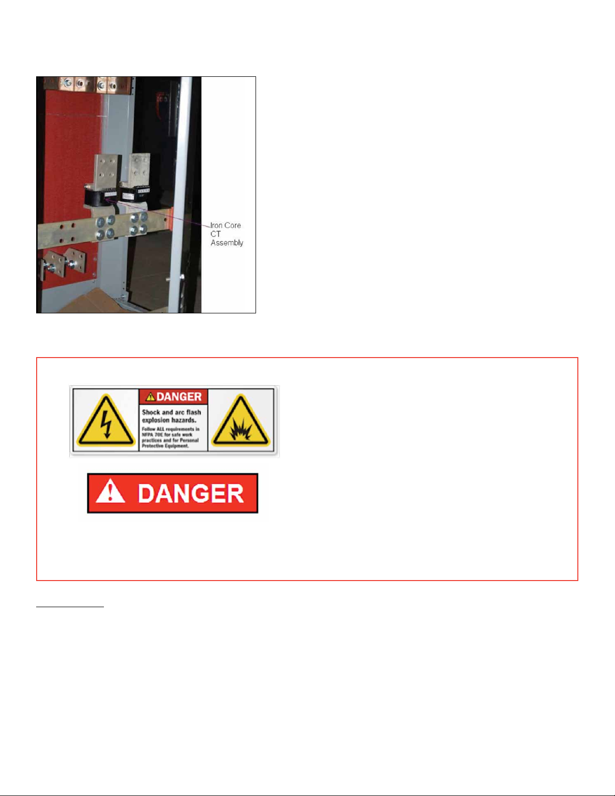
Figure 1. Neutral—AK25/50 Iron Core
Current Transformer Assembly
Neutral CT in Cable/Bus Compartment
• Turn off all power to switchgear. Tagout
and lockout main source, up-stream or
main breaker.
• Failure to comply with these instructions
will result in death or serious injury from
severe burns caused by arc flashing that
has exceedingly high temperatures.
• Always wear personal protection equipment
according to OSHA standards and appropriate
to the severity of potential burns.
• Ensure only qualified personnel install, operate, service, and maintain all electrical equipment.
Tools required: Wrenches, Wire stripper, wire cutter, continuity tester.
1. Ensure that the LVS has been de-energized and the breaker in the compartment, being retrofitted, are
switched off and removed from the LVS.
2. Open the door at the rear of the compartment to access the cable/bus compartment of the LVS.
3. Note that the existing neutral CT assemblies are usually mounted vertically on two copper bus bars
placed horizontally.
4. Make a note of the neutral disconnect assembly orientation and the polarity of the wire connections.
This is needed so that the same orientation is maintained when the new CT assembly is installed.
Neutral Assemblies Manual
3
DEH-41531 02/12
Page 5
5. Disconnect the wires that are attached to the existing CT assemblies and place them in a way that they do not
interfere with the replacement of the CT assemblies.
6. Replace the neutral disconnect wiring with a new wire. This should be routed directly to the secondary disconnects of the cassette assembly.
7. Unfasten and remove the bolts that hold the neutral disconnects assemblies to the horizontal bus bars. Keep the
hardware in a handy location for reassembling.
8. Care should be taken while handling the CT assemblies such that they do not get damaged or damage other
components within the LVS.
9. Replace the old CT assembly with the new Rogowski assembly (Figure 2 or Figure 3, depending if it’s AK25 or
AK50 switchgear) on the horizontal bus bars and fasten it using the hardware previously removed. The position of
the new CT assembly should match that of legacy, noted during Step 4.
10. Connect the wires back to the Rogowski CT assembly leads. Maintain the same polarity as that of the legacy CT
connections, noted during Step 4.
11. Check for continuity from the CT leads to the secondary disconnects on the retrofit EntelliGuard ACB.
12. Always verify that the new Rogowski assembly is properly installed before activating it.
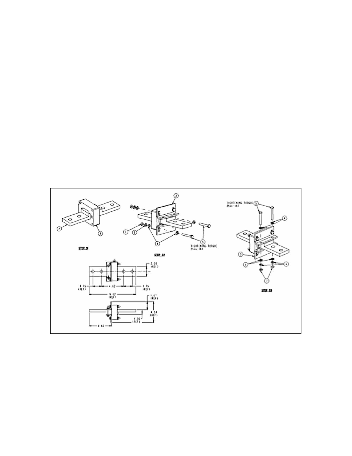
Figure 2. AKD-5—AK25 Neutral Bus Rogowski ASM 10108212
DEH-41531 02/12
Neutral Assemblies Manual
4
Page 6

Figure 3. AKD-5—AK50 Neutral Bus Rogowski ASM 10108216
AKD-5—Neutral Sensor Packaging
• TheNeutralSensorisconstructedusingaphasesensorencapsulatedappropriatelytomeetinsulation
and durability requirements.
• LeadwiresareUL-recognizedtype18AWGorlarger,ratedat600V.
• Leadwiresare6feetinlength,minimum.
• Leadwiresarecoloredwhiteandblack.
• Thewhitewireisconnectedtothe“positive”polaritytermination.
• Theblackwireisconnectedtothe“negative”polaritytermination.
• Sensorwindowcrosssectionconformstocriteriaasfoundinthetablebelow(Table 1):
Table 1. Frame Ratings and Sensor Areas
Frame & Rating Sensor Window minimum area (in2)
Frame 1 / 2000A 2.0
Frame 2 / 3200A 3.2
Frame 3 / 6400A 6.4
The Frame 3 neutral sensor is implemented as two separate sensors, similarly to the phase sensors in the circuit
breaker. Frame 3 neutral bus assemblies provide two independent parallel conductors in the neutral bus such
that the neutral current is divided between the two sensors.
A special neutral bus section is provided within the switchgear to accommodate the specific form factor of each
Rogowski—this is not the design responsibility of the Rogowski vendor.
• EncapsulationmaterialsareULrecognizedandsuitableforoperationat130C.
• Neutralsensorsofagivenratingmatchallcharacteristicsofthephasesensors.
Neutral Assemblies Manual
5
DEH-41531 02/12
Page 7

AKD-6/8—Neutral Rogowski Current Transformer (CT)
Neutral Disconnect Assembly (AKD-6—Breaker Side)
Figure 4 shows an exploded view of the breaker side neutral disconnect assembly for the AKD-6 AKR30/30H/50/50H
retrofills. These are available pre-installed and wired at the factory.
Figure 4. Neutral Disconnect Assembly for the AKD-6 AKR30H\50H Retrofill
AKR AKD6 BREAKER SIDE:
P/N 10105292G1
COMPARTMENT: P/N 10108266G1
Neutral Disconnect Assembly (Bus Compartment)
The AKD-6 EntelliGuard R Circuit Breaker uses an air-core Rogowski Current sensor to measure current level vs. an
iron core CTs used in the legacy AK, AKR breakers. For the Retrofill to calculate the current levels on a 4-wire circuit,
the Neutral Iron Core CT in the cable compartment needs to be replaced with a Rogowski style CT.
The Rogowski CT comes mounted on copper bars matching the same hole-pattern as the existing neutral bar. The
existing wires and hardware can be reused if they are not damaged. Note, if existing wires need to be replaced, then
a continuous wire runs from the CT to the Neutral Disconnect in the cubicle. If the threads on the hardware have
become worn out, they need to be replaced with new ones before installation.
DEH-41531 02/12
Neutral Assemblies Manual
6
Page 8

AKD-6/8—Rogowski Assembly Part Numbers
Table 2. AKD-6—Rogowski Assemblies (Neutral Bus Part Numbers)
Breaker/Switchgear Rogowski Assembly or Neutral Bus Bar Part Number Figure References for Assembly Drawings
AKD6 400A
AKD6 600A
AKD6 800A
AKD6 1000A
AKD6 1200A
AKD6 1600A
10108266G1
10108266G2
10108266G3
10108266G4
10108266G5
10108266G6
Figure 9. Neutral Bus Rogowski ASM 10108266
AKD-6/8—Rogowski Assemblies
• Figure 5 (assembly drawing with photo, Figure 6) displays Rogowski ASM 10108212.
• Figure 7 (assembly drawing with photo, Figure 8) displays Rogowski ASM 10108216.
• Figure 9 (assembly drawing with photo, Figure 10) displays Rogowski ASM 10108266.
Figure 5. Neutral Bus Rogowski ASM 10108212
Figure 7. Neutral Bus Rogowski ASM 10108216
Figure 6. Neutral Bus Rogowski ASM 10108212 Photo
Figure 8. Neutral Bus Rogowski ASM 10108216 Photo
Neutral Assemblies Manual
7
DEH-41531 02/12
Page 9

Figure 9. Neutral Bus Rogowski ASM 10108266 Figure 10. Neutral Bus Rogowski ASM 10108266 Photo
Neutral CT assembly in Cable/Bus Compartment
1. Ensure that the LVS has been de-energized and the breaker in the compartment being retrofit are switched
off and removed from the LVS.
2. Open the door on the rear of the compartment to gain access the Cable Bus compartment of the LVS.
3. The existing neutral CT assemblies are usually mounted vertically on two copper bus bars placed horizontally.
4. Disconnect the wires that are attached to the existing CT assemblies and place them such that they do not
interfere with the replacement of the CT assemblies.
5. Unfasten and remove the bolts that hold the neutral disconnect assemblies to the horizontal bus bars.
Keep the hardware in a secure location for reassembly.
6. Care should be taken while handling the CT assemblies such that they do not fall down or damage other
components within the LVS.
7. Replace the old CT assembly by the new Rogowski assembly on the horizontal bus bars and fasten it using
the hardware previously removed.
8. Connect the wires back to the Rogowski CT assembly leads. In case of damaged wire, the same must be
replaced with new ones as already mentioned.
9. Check for continuity from the CT leads to the plungers located on the neutral-disconnect assemblies in the
LVS compartment .
10. Verify that the new Rogowski assembly is installed and ready for use.
Tools required: Wrenches, Wire stripper, wire cutter, continuity tester
DEH-41531 02/12
Neutral Assemblies Manual
8
Page 10

Wiring Diagram for the AK/AKR Retrofill
Neutral Assemblies Manual
9
DEH-41531 02/12
Page 11

Legacy Specifications
DEH-41531 02/12
Neutral Assemblies Manual
10
Page 12

Ordering Rogowski Replacements
Neutral Assemblies Manual
11
DEH-41531 02/12
Page 13

Notes
DEH-41531 02/12
Neutral Assemblies Manual
12
Page 14

GE Energy
41 Woodford Avenue
Plainville, CT 06062
www.geindustrial.com
© 2012 GE Company
imagination at work
DEH-41531 02/12
 Loading...