

Page 1
GE Consumer & Industrial
Power Protection
M
ISM_Cabinet_GE_01
T
SitePro 10 – 500 kVA / 400Vac CE / From Series 6 & SitePro A 10 – 300 kVA / 480Vac UL / Series 6
Manufactured by:
GE Consumer & Industrial SA
General Electric Company
CH – 6595 Riazzino (Locarno)
Switzerland
T +41 (0)91 / 850 51 51
F +41 (0)91 / 850 51 44
www.gedigitalenergy.com
Operating Manual
Uninterruptible Power supply
Digital Energy™
ISM
Intelligent Synchronization Module
SG Series 80 –200 kVA / 400Vac CE & SG Series 10 –500 kVA / 480Vac UL
GE imagination at work
Page 2

Model:
Date of issue: 01.10.2005
File name: OPM_ISM_OPT_10K_M50_0GB_V021
Revision: 2.1
Identification No.
Up-dating
Revision Concerns Date
2.0 GE House-style & Configuration Warnings in Section 4 - Installation 15.01.2005
2.1 GE Consumer & Industrial SA 01.10.2005
COPYRIGHT © 2005 by GE Consumer & Industrial
ISM - Intelligent Synchronization Module / Series 0
All rights reserved.
The information contained in this publication is intended solely for the purposes indicated.
The present publication and any other documentation supplied with the ISM system is not to be
reproduced, either in part or in its entirety, without the prior written consent of GE.
The illustrations and plans describing the equipment are intended as general reference only and are
not necessarily complete in every detail.
The content of this publication may be subject to modification without prior notice.
Modifications reserved Page 2/34
OPM_ISM_OPT_10K_M50_0GB_V021.doc Operating Manual ISM – Intelligent Synchronization Module
Page 3

Dear Customer,
We thank you for selecting our products
and are pleased to count you amongst
our very valued customers at GE.
We trust that the use of the ISM
Intelligent Synchronization Module,
developed and produced to the highest
standards of quality, will give you
complete satisfaction.
Please read carefully the Operating
Manual, which contains all the
necessary information and describes all
you need to know about the use of the
ISM.
Thank you for choosing GE!
Manufactured by:
g
GE Consumer & Industrial SA
General Electric Company
CH – 6595 Riazzino (Locarno)
Switzerland
Distributed by:
Your service contact:
Modifications reserved Page 3/34
OPM_ISM_OPT_10K_M50_0GB_V021.doc Operating Manual ISM – Intelligent Synchronization Module
Page 4

Table of contents Page
SAFETY RULES............................................................................................................................................... 5
1
1.1 IMPORTANT SAFETY RULES...............................................................................................................................................................6
1.2 SAFETY SYMBOLS AND WARNINGS ..............................................................................................................................................7
2 DESCRIPTION................................................................................................................................................ 8
2.1 SCB - SYNCHRONIZATION OF CRITICAL BUSES.......................................................................................................................8
2.1.1 STS - Static Transfer Switch ...................................................................................................................................................................9
2.2 SERVICE AND TECHNICAL SUPPORT.......................................................................................................................................... 10
2.3 WARRANTY............................................................................................................................................................................................ 10
2.4 RECYCLING AT THE END OF SERVICE LIFE..............................................................................................................................10
3 LAYOUT........................................................................................................................................................ 11
3.1 LAYOUT ISM .......................................................................................................................................................................................... 11
4 INSTALLATION............................................................................................................................................ 12
4.1 TRANSPORT........................................................................................................................................................................................... 12
4.1.1 Dimensions and weight ........................................................................................................................................................................ 12
4.2 DELIVERY................................................................................................................................................................................................13
4.3 STORAGE................................................................................................................................................................................................ 13
4.4 PLACE OF INSTALLATION................................................................................................................................................................ 14
4.5 ELECTRICAL WIRING ......................................................................................................................................................................... 15
4.6 CONTROL BUS CABLES CONNECTION...................................................................................................................................... 18
4.7 UPS CONFIGURATION REQUIREMENTS....................................................................................................................................20
5 CONTROL PANEL........................................................................................................................................ 21
5.1 CONTROL PANEL ................................................................................................................................................................................ 21
5.2 TABLE OF FUNCTIONS AND INDICATIONS ON CONTROL PANEL.................................................................................. 21
6 LCD SCREEN................................................................................................................................................ 24
6.1 METERING MODE................................................................................................................................................................................ 25
6.2 ALARM..................................................................................................................................................................................................... 26
6.2.1 Events (Alarms and Messages) .......................................................................................................................................................... 27
6.2.1.1 Alarms list ...............................................................................................................................................................................................................27
6.2.1.2 Messages list......................................................................................................................................................................................................... 28
6.2.1.3 Event report ISM .................................................................................................................................................................................................. 29
6.3 USER PARAMETERS ...........................................................................................................................................................................30
7 OPERATION................................................................................................................................................. 31
7.1 PROCEDURES FOR SCB - SYNCHRONIZATION OF CRITICAL BUSSES.......................................................................... 31
8 MAINTENANCE ...........................................................................................................................................32
9 NOTES.......................................................................................................................................................... 33
9.1 NOTES FORM........................................................................................................................................................................................ 33
10 ANNEXE ...................................................................................ERRORE. IL SEGNALIBRO NON È DEFINITO.
10.1 TECHNICAL DIAGRAMS............................................................................. ERRORE. IL SEGNALIBRO NON È DEFINITO.
Modifications reserved Page 4/34
OPM_ISM_OPT_10K_M50_0GB_V021.doc Operating Manual ISM – Intelligent Synchronization Module
Page 5
1 SAFETY RULES
With this document, GE gives to the user all the necessary information about the correct installation
and connection of the ISM.
Please read carefully this Operating Manual before installing or operating the equipment.
If any problems are encountered with the procedures contained in this Operating Manual, please
contact the nearest Service Centre before you proceed.
All ISM installation, maintenance and service work should be performed by qualified service personnel
only.
The KNOWLEDGE and the FULLY compliance of the safety instructions and the warning
contained in this manual are
THE ONLY CONDITION
to avoid any dangerous situations during installation, operation, maintenance work, and
to preserve the maximum reliability of the UPS system.
NOTE !
While every care has been taken to ensure the completeness and accuracy of this
manual, GE assumes no responsibility or liability for any losses or damages
resulting from the use of the information contained in this document.
GE
Refuses any responsibility in case of non-observance,
unauthorised alterations or improper use of the
delivered UPS.
Modifications reserved Page 5/34
OPM_ISM_OPT_10K_M50_0GB_V021.doc Operating Manual ISM – Intelligent Synchronization Module
Page 6

1.1 IMPORTANT SAFETY RULES
SAVE THESE INSTRUCTIONS
This manual contains important instructions for model ISM - Intelligent Synchronization Module that
should be followed during installation and maintenance of the unit.
GENERAL
• Move the cabinet in a horizontal position in its original package to the final destination room.
• To lift the cabinets, use a forklift or lifting belts with spreader bars.
• Check for sufficient floor and elevator loading capacity.
• Check carefully the integrity of the ISM equipment.
In case you note some visible damage, do not put the ISM under voltage, but contact the nearest
Service Centre.
• WARNING! RISK OF ELECTRICAL SHOCK: Do not remove covers; there are no user serviceable parts
inside.
• This unit contains potentially hazardous voltages.
• All maintenance and service work should be performed by qualified service personnel.
INSTALLATION
• This equipment must be installed and connected only by trained personnel.
• This equipment is intended for use in a controlled indoor environment free of conductive
contaminants and protected against animals intrusion.
• WARNING! HIGH EARTH LEAKAGE CURRENT: earth connection is essential before connecting to AC
input!
• Do not install the equipment in an excessively humid environment or near water.
• Avoid spilling liquids on or dropping any foreign object into the equipment.
• The unit must be placed in a sufficiently ventilated area; the ambient temperature should not
exceed 35°C (95°F).
• It is important that air can move freely around and through the unit.
• Do not block the air vents.
• Avoid locations in direct sunlight or near heat sources.
STORAGE
• Store the equipment in a dry location; storage temperature must be within -25°C to 55°C
(-13°F to 131°F).
WARNING !
The installation and cabling of the options must be
performed by a QUALIFIED SERVICE PERSON.
Before operating be sure the installation is completely
switched off and voltage free
Modifications reserved Page 6/34
OPM_ISM_OPT_10K_M50_0GB_V021.doc Operating Manual ISM – Intelligent Synchronization Module
Page 7
1.2 SAFETY SYMBOLS AND WARNINGS
Safety warnings
The text of this manual contains some warnings to avoid risk to the persons and to avoid damages to
the UPS system and the supplied critical loads.
The non-observance of the warnings reminding hazardous situations could result in human injury and
equipment damages.
Please pay attention to the meaning of the following warnings and symbols:
WARNING !
Referred to procedures or operations which could cause damages to the persons or
to the system, when not correctly operated.
NOTE !
Warns the user about important operations or procedures described in this manual.
Safety symbols
When the text includes one or more of the following symbols, that means exist a potentially hazardous
situations.
Please remind the meaning of each symbol.
CAUTION
Related to all the potentially hazardous situations which may result in injury.
DANGER OF PARTS ELECTRICALLY LIVE
Related to all the situation with potentially hazardous voltage.
DANGER OF EXPLOSION
Used to indicate conditions where exploding parts can cause serious injury.
DANGER OF CRUSHING
Used when moving the equipment due to the heavy weight.
DANGER OF OVERHUNG LOAD
Used when the equipment is lifted by a crane.
DO NOT TOUCH
Risk of parts with hazardous voltages or parts in movement.
Modifications reserved Page 7/34
OPM_ISM_OPT_10K_M50_0GB_V021.doc Operating Manual ISM – Intelligent Synchronization Module
Page 8
2 DESCRIPTION
2.1 SCB - SYNCHRONIZATION OF CRITICAL BUSES
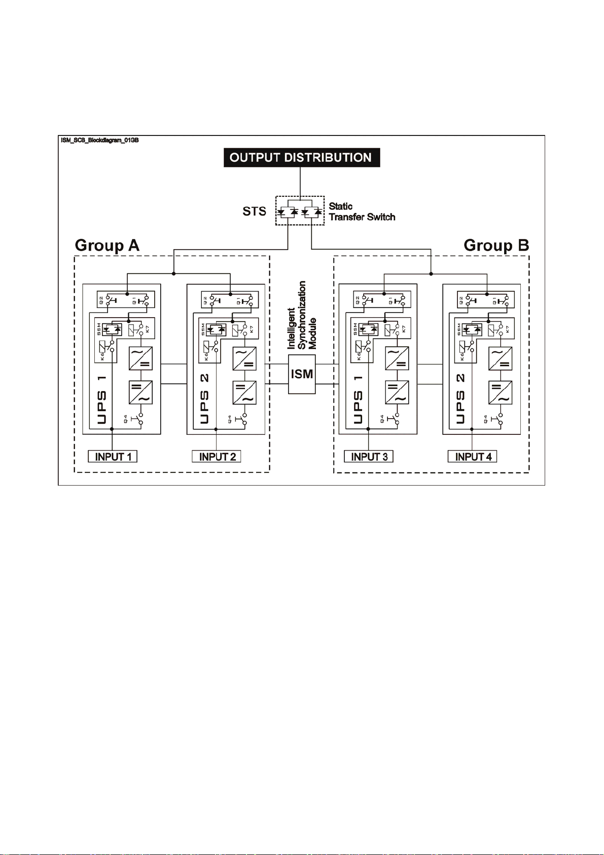
Fig. 2.1-1 SCB – Synchronization of Critical Busses block diagram
The UPS configuration in Fig. 2.1-1 enhances security, reliability and safety of a system for the power
supply to extremely critical loads.
Basically it is composed of 4 major blocks, see Fig 2.1-1:
• UPS Group A: this group can be minimum 1, maximum 6 units.
• UPS Group B: this group can be minimum 1, maximum 6 units.
• ISM – Intelligent Synchronization Module.
ISM (Intelligent Synchronization Module) allows synchronizing of two independent groups of parallel
UPS’s, each having a maximum of 6 UPS units of equal rating from 10 – 500 kVA.
• STS – Static Transfer Switch.
A Static Transfer Switch can select between 2 sources (UPS groups).
As standard the Static Transfer Switch will supply the load from the preferred source.
In case the source would fail it will transfer the load to the second source.
A condition is that both sources are synchronized continuously, also on battery operation.
Each group of UPS’s are independent and capable to supply the full load, eventually redundant.
Each unit in the group is synchronized to its Master, which in return synchronizes to the utility voltage, if
available.
Modifications reserved Page 8/34
OPM_ISM_OPT_10K_M50_0GB_V021.doc Operating Manual ISM – Intelligent Synchronization Module
Page 9
r
r
t
Features & benefits:
• Redundant Power Supply providing highest reliability.
• Redundant Communication Bus tolerating an accidental cable cut.
• CRC Code (Cyclic Redundancy Check) for error free communication.
• High Precision Synchronization offering seem less transfer from one source to the other.
• Top and Bottom Cable access for easy installation.
• Compatible with GE SitePro (only series 6) and SG Series UPS and with GE’s unique RPA concept.
• Global Power Supply Voltage for worldwide usage (208, 400 or 480 VAC – 50 / 60 Hz).
• Synchronizes 2 groups of max. 6 UPS units (ranging from 10 - 500 kVA) each offering great
flexibility.
• User Friendly Control Panel providing complete information on the spot.
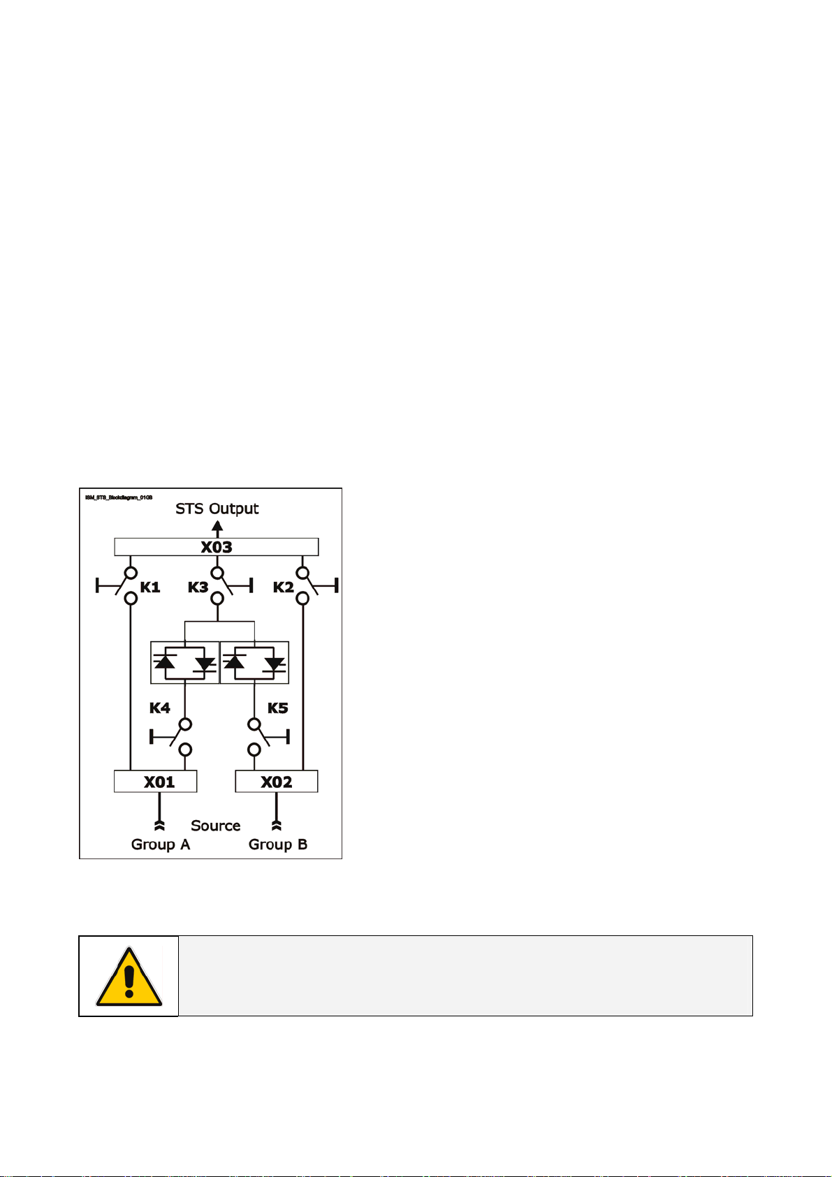
2.1.1 STS - Static Transfer Switch
Fig. 2.1.1-1 STS - Static Transfer Switch block diagram
The STS is designed for the switching of two alternative
power sources without interruption of the supply to
energy receivers.
The STS is connected to two sources of electrical powe
with terminal X01 for the Group A source and X02 fo
the Group B source.
Depending on current settings and system status, one
of the two sources (Group A or Group B) is connected to
the output terminal X03 (STS Output).
K1, K2, K3, K4 and K5 are manually operated circui
breakers.
K1 and K2 are normally open, while K3, K4 and K5 are
normally closed.
X01, X02 and X03 are terminals.
NOTE !
For installation procedures and functional descriptions of the STS, please
consult the appropriate Operating Manual.
Modifications reserved Page 9/34
OPM_ISM_OPT_10K_M50_0GB_V021.doc Operating Manual ISM – Intelligent Synchronization Module
Page 10
2.2 SERVICE AND TECHNICAL SUPPORT
Stamp of your Dealer or local responsible of the Technical Assistance
(see page 3)
For any request of technical support please
contact the supplier who provided the system.
2.3 WARRANTY
GE operates through its authorised agents and warrants that the standard products will be free of
defects in materials and workmanship for a period of 12 months, after the date of the invoice, or such
other period as may be specified.
NOTE !
This warranty does not cover failures of the product which result from incorrect
installation, misuse, alterations by persons other than authorised agents, or
abnormal working conditions.
2.4 RECYCLING AT THE END OF SERVICE LIFE
NOTE !
This product has been designed to respect the environment, using materials and
components respecting eco-design rules.
It does not contain CFCs (Carbon Fluor Clorid) or HCFCs (Halogen Carbon Fluor
Clorid).
GE, in compliance with environment protection recommends to the User
that the ISM equipment, at the end of its service life, must be recovered
conforming to the local applicable regulations.
Modifications reserved Page 10/34
OPM_ISM_OPT_10K_M50_0GB_V021.doc Operating Manual ISM – Intelligent Synchronization Module
Page 11

3 LAYOUT
3.1 LAYOUT ISM
ISM_Cabinet_GE_01
M
T
ISM_LBS_Cabinet open_01
Fig. 3.1-1 ISM general view
Fig. 3.1-2 ISM internal view
SYNC
SYNC
AUTO
ISM_LBS_Cabinet open_02
MAINTENANCE MAINTENANCE
INVERTER OK
BYPASS OK
ISM_LBS_Control panel_01
INVERTER
BYPASS
METERING
ALARMS
PARAMETERS
OFF
SYNC MASTER
A B
STS
LOAD
Fig. 3.1-4 Control panel
ALARM SERVICE
GROUP BGROUP A
+
-
ENTER
INVERTER
BYPASS
INVERTER OK
BYPASS OK
B SYNC TO AA SYNC TO B
MUTE
Fig. 3.1-3 ISM internal view
Modifications reserved Page 11/34
OPM_ISM_OPT_10K_M50_0GB_V021.doc Operating Manual ISM – Intelligent Synchronization Module
Page 12

4 INSTALLATION
4.1 TRANSPORT
The ISM is fixed on a transport socket suitable for a forklift, which includes a special layer of Ethafoam to
protect the equipment against the transport shock.
Normally the ISM is packaged within a carton box.
On request the equipment can be packaged in a wooden case.
Move the ISM in its original package to the final destination room.
Do not stack other packages on top: they could damage the cabinet.
NOTE !
When moving the ISM, pay attention to:
WARNING !
When loading / downloading and when
moving the ISM, it is forbidden:
When loading / downloading and when
moving the ISM, pay attention to:
4.1.1 Dimensions and weight
m
m
0
5
3
"
8
7
.
3
1
m
m
4
6
2
"
9
3
.
0
m
m
3
4
"
0
7
.
1
1.66"
42mm500mm42mm
1
FRAGILE
SENSITIVE
TO DAMPNESS
m
m
3
4
"
0
7
.
1
0.55"
14mm
1
9
0
m
m
7
.
4
8
"
Dimensions ISM
SENSITIVE
TO HEAT
SENSITIVE
TO FROST
350 mm x 190 mm x 584 mm
M
T
13.78” x 7.48” x 23.00 inches
19.69"1.66"
23.00"
584mm
ISM
ISM_Cabinet dimension s_GE_01
20 Kg / 44 lbs 30 Kg / 66 lbs
Weight ISM
ISM with
standard package
Fig. 4.1.1-1 ISM cabinet dimensions
NOTE !
The weight is marked outside the package!
Modifications reserved Page 12/34
OPM_ISM_OPT_10K_M50_0GB_V021.doc Operating Manual ISM – Intelligent Synchronization Module
Page 13

4.2 DELIVERY
When delivered, check carefully the package integrity and the physical conditions of the ISM
equipment.
In case of any damage sustained during transport, immediately inform the carrier and contact your
local Service Centre.
A detailed report of the damage is necessary for any insurance claim.
NOTE !
A damaged ISM must never be installed or connected to power!
4.3 STORAGE
The equipment is carefully packed for transport
and storage so that it is in a perfect condition
when eventually installed.
Never leave an ISM outside the building and do
not store the ISM one on top of the other.
It is recommended to store the ISM in its original
package in a dry, dust free room and far away
from chemical substances, with temperature
not exceeding -25°C to 55°C (-13°F to 131°F).
Some important functions of the ISM are defined by parameters stored in a RAM memory.
The RAM is supplied by a small backup battery located on the Control Unit board.
If the storage time of the ISM exceeds 1 year, these functions should be verified by an authorised
Service Centre before putting the ISM into operation.
NOTE !
In case of storage of the ISM pay attention to:
FRAGILE
SENSITIVE
TO DAMPNESS
SENSITIVE
TO HEAT
SENSITIVE
TO FROST
Modifications reserved Page 13/34
OPM_ISM_OPT_10K_M50_0GB_V021.doc Operating Manual ISM – Intelligent Synchronization Module
Page 14

4.4 PLACE OF INSTALLATION
The ISM should be installed in a restricted area where only qualified personnel should be admitted.
The place of installation should be clean, dust-free, and provided with proper ventilation or air-
conditioning.
We strongly advice that the ambient temperature should not exceed 20° to 25°C / 68° to 77°F (max.
35°C / 95°F).
NOTE !
The installation of the ISM must be executed by QUALIFIED PERSONNEL ONLY.
A single-phase power outlet should be provided near the ISM for connection of power tools or test
equipment. This outlet must be grounded.
ISM positioning
G
R
O
U
P
A
Min.
400mm / 16"
G
R
O
ISM_Cabinet_GE_03
M
T
ISM_LBS_Cabinet disposition_01GB
U
P
S
3
U
P
S
2
U
P
S
1
U
P
S
1
Fig. 4.4-1 ISM positioning
U
P
U
P
B
S
2
U
P
S
3
The ISM should be mounted flush to a wall.
Clearance around the front of the ISM should be sufficient to enable free passage of personnel with
the door fully open, and to allow sufficient airflow for the ventilation.
Recommended minimum clearance between the ceiling and the top of the ISM should be 400 mm
(16 “) for proper cooling air exhaust.
NOTE !
The bolts used for fixing the ISM to the wall must be adequate for its weight.
Modifications reserved Page 14/34
OPM_ISM_OPT_10K_M50_0GB_V021.doc Operating Manual ISM – Intelligent Synchronization Module
Page 15

4.5 ELECTRICAL WIRING
WARNING !
The installation and connection must be performed by QUALIFIED SERVICE
PERSONNEL only.
Refer to the “Safety prescriptions - Installation” described on page 6.
Carefully read the following recommendations before proceeding:
• Ensure that the AC external isolators are Off, and prevent their inadvertent operation.
• Do not close any external isolators prior the commissioning of the equipment.
• The input / output cables must be put in order and fixed, taking care to avoid risk of short-circuit
between different poles.
• The earthing connection of the electrical system must be in accordance with local regulation.
Input overcurrent protection and wire sizing
Fig. 4.5-1 Input overcurrent protection and wire sizing
For correct rating of fuses and cable sections for input power of the ISM see data indicated in the
tables below.
Fuses AgL or Circuit breakers
Group A: F5 – F6 & Group B: F7 – F8 2 x (2 x 2 A)
Wire sizing
Group A: L1 + L2 + PE & Group B: L1 + L3 + PE
Min. 3 x 1.5 mm
2
/ Max. 3 x 2.5 mm
Min. 3 x 16 AWG / Max. 3 x 14 AWG
2
NOTE !
The delivery and installation of fuses and input connections of the ISM are at the
customer’s expense, unless agreed otherwise.
Modifications reserved Page 15/34
OPM_ISM_OPT_10K_M50_0GB_V021.doc Operating Manual ISM – Intelligent Synchronization Module
Page 16

Openings for input and output cable connections
B
ISM_LBS_Cabinet input cable_01
A
B
B
Fig. 4.5-2 Opening on top/bottom of the cabinet for input and output cables
Connection of power supply cables
A
ISM openings are provided
either on top or on the
bottom of the cabinet for
the connection of input and
output cables.
Pay attention to the
position of these openings,
when choosing the
placement of the ISM.
Position of the input and the
output can be modified by
exchanging the cover plates
“A and B” (see Fig. 4.5-2).
0
Fig. 4.5-3 Transformer TR1 and TR2
ISM_LBS_TR1-TR2_01
NOTE !
Verify the input voltage for power supply and connect the cable without label to the
corresponding input of the terminal.
Possible voltages are 208V, 400V and 480V (Phase – Phase. See Fig. 4.5-3).
Modifications reserved Page 16/34
OPM_ISM_OPT_10K_M50_0GB_V021.doc Operating Manual ISM – Intelligent Synchronization Module
Page 17

Fuses rating
NOTE !
Verify for correct fuse rating “F1 - F2
- F3 - F4” on dependence of the
power supply input voltage,
according to the table below.
In case of replacement the same
type and the same rating must be
F1-F2-F3-F4
ISM_LBS_F1-2-3-4_01
Fig. 4.5-4 Fuses rating
used.
The replacement of fuses must be
performed by QUALIFIED SERVICE
PERSONNEL only.
For 208 VAC 0.75 A Fuse type Class CC – Time Delay – 13/32” x 1 1/2” – 600 VAC
For 400 VAC 0.3 A Fuse type Class CC – Time Delay – 13/32” x 1 1/2” – 600 VAC
For 480 VAC 0.3 A Fuse type Class CC – Time Delay – 13/32” x 1 1/2” – 600 VAC
Connection of power supply input cables
L1
L2
PE
GROUP AGROUP B
L1
L3
PE
Input glands are suitable for cables having diameters: from 6 mm to 12 mm / 2.37” to 4.73”
L1 Phase L1 from Output Load Group A PE Ground from Output Load Group A
L2 Phase L2 from Output Load Group A
Fig. 4.5-4 Connection of power supply input cables
ISM_LBS_Connection power_01
ISM Input A
Group A Group B
ISM Input B
L1 Phase L1 from Output Load Group B PE Ground from Output Load Group B
L3 Phase L3 from Output Load Group B
Modifications reserved Page 17/34
OPM_ISM_OPT_10K_M50_0GB_V021.doc Operating Manual ISM – Intelligent Synchronization Module
Page 18

4.6 CONTROL BUS CABLES CONNECTION
WARNING !
The installation and connection must be performed by QUALIFIED SERVICE
PERSONNEL only.
Refer to the “Safety prescriptions - Installation” described on page 6.
Carefully read the following recommendations before proceeding:
• Ensure that the AC external isolators are Off, and prevent their in adverted operation.
• Do not close any external isolators prior to the commissioning of the equipment.
• The input / output cables must be put in order and fixed, taking care to avoid risk of short-circuit
between different poles.
• The earthing connection of the electrical system must be in accordance with local regulations.
The standard length of the control
bus cable between ISM and the
first unit of each group is 12 m / 40
ft.
Maximum distance between ISM
and the last unit of each group is
85 m / 279 ft.
L max. :
85 m – [(No. of UPS – 1) x 12 m]
279 ft – [(No. of UPS – 1) x 40 ft]
Maximal number of UPSs in one
Fig. 4.6-1 Diagram showing the maximum allowable length of communication cables
group is 6.
ISM_LBS_CBC connection_01GB
Fig. 4.6-2 Connection of the cables of the communication
Control bus cables
JA1
Group A
JB2
JB1
J53
Group B
P6
JA2
JA1
JB2
JB1
J63
Control bus cables
P5
JA2
J52
J62
bus to P5 / P6 – Parallel bus interface
ISM_LBS_CBC connection_02GB
Control bus cables
Group A
Control bus cables
Group B
Fig. 4.6-3 Internal connection of the communication bus cables
Modifications reserved Page 18/34
OPM_ISM_OPT_10K_M50_0GB_V021.doc Operating Manual ISM – Intelligent Synchronization Module
Page 19

G
R
O
U
P
ISM_LBS_CBC connection_03GB
Q1
OFF
ON
OFF
ON
Q2
U
P
S
3
Control bus cables routing
Fig. 4.6-4 Connection of the communication bus cables from ISM to UPS’s Group A and Group B
U
P
S
A
Q1
OFF
OFF
ONON
Q2
2
Q1
OFF OFF
ONON
Q2
U
P
S
1
Control bus cables Group A
From ISM to UPS 1 / Group A
See Fig. 4.6-5/6
Control bus cables Group B
(from ISM to UPS 1 / Group B)
I
S
M
F
i
g
.
4
.
6
-
1
P5
P6
See Fig. 4.6-5/6
/
2
G
R
O
U
P
B
Q1
OFF
ON
OFF
ON
Q2
U
P
S
1
Q1
OFF
ON
OFF
ON
Q2
U
P
S
2
Q1
OFF
ON
OFF
ON
Q2
U
P
S
3
Place and fix the cables JA and JB with the appropriate clamps inside the UPS cabinets.
Pay attention to the fact, that routing of cables shall allow the removal of the protection covers.
NOTE !
Pay attention when cabling and routing the bus cables JA and JB inside the UPS
cabinet.
In case the unit should be removed from the system, the control bus cables Group A
and Group B must be removed from the cabinet without disconnecting them from
the metal plates where are located the sockets JA and JB. Please contact your
Service Centre.
For reliability reasons the cables JA and JB connecting the units should be run in separated
protected conduits, as well as separated from the power cables.
It is important that the cable JA is as long as cable JB.
ISM_LBS_RPA-IM0048_01
JB1
JP1 JP2
IM 0048
JP2
JP1
JP4
JP3
JB
ISM_LBS_RPA-IM0048_02GB
JB
Control Bus cable from ISM
JP2JP1
IM 0048
JB
JP2
JP1
JP4
JP3
JA1
JP4
JP3
JA
JA
Control Bus cable from ISM
JP4
JP3
JA
Fig. 4.6-5 PCB “P34 – Parallel Bus Interface” of UPS number 1 of either
Group A or B, prior to the connection with ISM
The Jumpers JP1, JP2, JP3 and JP4 ARE
INSERTED.
Fig. 4.6-6 PCB “P34 – Parallel Bus Interface” of UPS number 1 of
either Group A or B, after
the connection with ISM
The Jumpers JP1, JP2, JP3 and JP4 MUST BE
REMOVED.
NOTE !
Since the position of PC Board “P34 – Parallel Bus Interface” inside the UPS changes
between the various UPS output powers, it’s recommended to consult the
appropriate Operating Manual for cable connections.
Modifications reserved Page 19/34
OPM_ISM_OPT_10K_M50_0GB_V021.doc Operating Manual ISM – Intelligent Synchronization Module
Page 20

4.7 UPS CONFIGURATION REQUIREMENTS
WARNING !
The installation and connection must be performed by QUALIFIED SERVICE
PERSONNEL only.
Refer to the “Safety prescriptions - Installation” described on page 6.
NOTE !
The UPSs are already correctly configured, if they have been ordered and supplied
with the ISM.
Otherwise please make sure that UPSs connected with the ISM mount:
• P13 - IM0086 RPA Board with same software version as on the ISM.
• Following software versions on P3 - IM0007 Control Board:
- For SitePro units: U2, U3: version 2.08 or higher; U36: version 7.0 or higher.
- For SG Series units: U2, U3: version 3.06 or higher; U36: version 7.0 or higher.
Modifications reserved Page 20/34
OPM_ISM_OPT_10K_M50_0GB_V021.doc Operating Manual ISM – Intelligent Synchronization Module
Page 21

5 CONTROL PANEL
5.1 CONTROL PANEL
ALARM SERVICE
GROUP BGROUP A
+
-
ENTER
INVERTER
BYPASS
INVERTER OK
BYPASS OK
B SYNC TO AA SYNC TO B
MUTE
METERING
ALARMS
PARAMETERS
SYNC
OFF
SYNC MASTER
A B
STS
LOAD
SYNC
AUTO
INVERTER
BYPASS
MAINTENANCE MAINTENANCE
INVERTER OK
BYPASS OK
ISM_LBS_Control panel_01
Fig. 5.1-1 General Control Panel
5.2 TABLE OF FUNCTIONS AND INDICATIONS ON CONTROL PANEL
ISM_LBS_CP 1_01
SYNC
AUTO
SYNC
OFF
Fig. 5.2-1 Control Panel – Part 1
SYNC
AUTO
SYNC AUTO – Green LED
When lit, it indicates that the sync command is active and that the inverters of
Group A and B will be synchronized to the selected “Super Master”.
The “Super Master” will be automatically chosen.
SYNC
OFF
SYNC OFF – Red LED
When lit, it indicates that the sync command is disabled due to one or both of the
following conditions:
• SYNC command is OFF;
• One of the two (2) UPS groups is not present.
ALARM
ALARM – Yellow LED
General alarm condition.
It blinks when one or more alarm is activated. The internal buzzer is ON.
The LED remains lighted (with alarm condition still present) and the buzzer stops
as the key “mute” has been pressed.
SERVICE
SERVICE – Yellow LED
When lit it indicates that a regular maintenance service is needed.
May be reset by a service technician only. See Section 8 – Maintenance.
ALARM SERVICE
Modifications reserved Page 21/34
OPM_ISM_OPT_10K_M50_0GB_V021.doc Operating Manual ISM – Intelligent Synchronization Module
Page 22

A
GROUP BGROUP A
INVERTER
BYPASS
MAINTENANCE MAINTENANCE
SYNC MASTER
AB
INVERTER
BYPASS
INVERTER
BYPASS
MAINTENANCE
INVERTER OK
BYPASS OK
A SYNC TO B
B SYNC TO
ISM_LBS_CP 2_01
A
B
INVERTER OK
BYPASS OK
STS
LOAD
INVERTER OK
BYPASS OK
B SYNC TO AA SYNC TO B
Fig. 5.2-2 Control Panel – Part 2
SYNC MASTER A (B) – Green LED
Pushbuttons commands:
A When pressed, Group A will be the synchronization “Super Master” and Group
B will synchronize to Group A.
The “SYNC MASTER A” LED will be lit.
Pressing this button disables the automatic “Super Master” selection.
B When pressed, Group B will be the synchronization “Super Master” and Group
A will synchronize to Group B.
The “SYNC MASTER B” LED will be lit.
Pressing this button disables the automatic “Super Master” selection.
The SYNC MASTER A (B) green LED, indicates whether Group
A or B is the Super Master.
OUTPUT SYNC – Green LED
When lit, it indicates that the UPS outputs of Groups A and B are synchronized
and within the allowed limits.
This indication is derived from comparing the output of the second UPS group to
the output of the selected “Super Master” group.
When blinking, it indicates that the UPS outputs of Groups A and B are
synchronizing.
OUTPUT – Green LED
The corresponding LED will be lit, depending on the UPS output status of Group A
(or B): INVERTER, BYPASS (Automatic Bypass) or MAINTENANCE (Manual Bypass).
INVERTER OK – Green LED
When lit it indicates that the inverter power to UPS Group A (or B) is available and it
is within the allowed tolerance.
BYPASS OK – Green LED
When lit, it indicates that the bypass power to UPS Group A (or B) is available and it
is within the allowed tolerance.
A SYNC TO B – Green LED
When lit, it indicates that the UPS outputs of Groups A and B are synchronized and
within the allowed limits. Group B is the synchronization Super Master.
B SYNC TO A – Green LED
When lit, it indicates that the UPS outputs of Groups A and B are synchronized and
within the allowed limits. Group A is the synchronization Super Master.
Modifications reserved Page 22/34
OPM_ISM_OPT_10K_M50_0GB_V021.doc Operating Manual ISM – Intelligent Synchronization Module
Page 23

MUTE
ISM_LBS_CP 2_01
Fig. 5.2-3 Control Panel – Part 3
LAMP TEST
Key to test the control panel LED’s and buzzer.
(Pressing this key causes all the LED’s to light and the buzzer to
sound 3 times).
MUTE
METERING
ALARMS
PARAMETERS
MUTE
Key to reset general alarm and buzzer.
+
-
ENTER
ISM_CP LCD_01
Fig. 5.3-1 Control Panel - LCD screen
See Section 6 – LCD SCREEN
Modifications reserved Page 23/34
OPM_ISM_OPT_10K_M50_0GB_V021.doc Operating Manual ISM – Intelligent Synchronization Module
Page 24

6 LCD SCREEN
METERING
ALARMS
PARAMETERS
ISM_CP LCD_01
+
-
ENTER
Fig. 6-1 LCD screen
The user interface consists of a back lit LCD screen having:
• 4 lines with 20 characters (standard version for Latin characters);
and
• 6 keys (the function is described for each operating mode).
The operation is extremely simple and is structured on three important main menus related to the ISM
operation, as follows:
METERING An ISM must offer some metering information for the user to be able to examine
the operating status at any time.
ALARMS In case of abnormal functioning, the ISM must keep a history of what has
happened as a series of events.
PARAMETERS The user must be able to program certain functions of the ISM (user parameters,
accessible without password) to his needs.
LCD screen standard version
METERING
LCD screen
+
ALARMS
PARAMETERS
4 rows x
20 characters
-
ENTER
The 3 buttons existing on the left side of the screen are used to activate the operating modes, while the
buttons on the right side are used to carry out functions inside these operating modes.
Modifications reserved Page 24/34
OPM_ISM_OPT_10K_M50_0GB_V021.doc Operating Manual ISM – Intelligent Synchronization Module
Page 25

6.1 METERING MODE
The metering mode is entered any time when the metering button is pressed.
While in this mode the LCD will display a series of screens containing metering information.
In this mode the buttons perform the following functions:
METERING Scrolls forward to the next screen.
ALARMS Abandons the metering mode and enters the alarms mode.
PARAMETERS Abandons the metering mode and enters the parameters mode.
+ Scrolls forward to the next screen.
– Scrolls backward to the previous screen.
ENTER Displays the main screen for this mode.
METERING
ALARMS
PARAMETERS
INTELL. SYNC MODULE
A: LOAD ON INVERTER
B: LOAD OFF
This screen displays the current status of the synchronization command and the UPS outputs (for both
Group A and B).
The information offered by this screen consists of:
• Synchronization: The status of the synchronization command (A sync to B, B sync to A or Sync
OFF).
• Group A: The source of the power supplied to the Load (LOAD ON INVERTER, LOAD ON
BYPASS, LOAD ON MAN. BYP. or LOAD OFF).
• Group B: The source of the power supplied to the Load (LOAD ON INVERTER, LOAD ON
BYPASS, LOAD ON MAN. BYP. or LOAD OFF).
METERING
ALARMS
PARAMETERS
OUTPUT STATUS
This screen displays the load of UPSs output (for both Group A and B).
The information offered by this screen consists of:
• Synchronization status between UPSs of Group A and B;
• The load amount as a percentage of the nominal load of Group A (referred to the most loaded
phase);
• The load amount as a percentage of the nominal load of Group B (referred to the most loaded
phase).
METERING
ALARMS
PARAMETERS
MISCELLANEOUS
ISMOperTime
SW Version
S/N:
This screen displays miscellaneous information.
The information offered by this screen consists of:
• The total operating time of the ISM (in hours).
• The software version.
• The serial number.
A sync to B
Synchronized
Load A = 50%
Load B = 20%
:
:
72-97756
123451h
XXX-YYY
+
-
ENTER
+
-
ENTER
+
-
ENTER
Modifications reserved Page 25/34
OPM_ISM_OPT_10K_M50_0GB_V021.doc Operating Manual ISM – Intelligent Synchronization Module
Page 26

6.2 ALARM
The alarms mode is entered any time when the ALARMS button is pressed.
The LCD will display a series of screens corresponding to the last 256 events, one event per screen.
The buttons perform the following functions:
METERING Abandons alarms mode and enters metering mode.
ALARMS Next screen.
PARAMETERS Abandons the alarms mode and enters the parameters mode.
+ Scrolls forward to the next screen.
– Scrolls backward to the previous screen.
ENTER Displays the main screen for this mode.
The events displayed are the standard GE events as described in the Section 6.2.1 - EVENTS (Alarms
and Messages).
The information displayed includes:
• The exact date and time when the event occurred.
• The number of the event, 255 being the most recent event, and 0 the oldest.
• The standard GE code for the event and the machine status word.
• An explicit text description of the event.
METERING
ALARMS
PARAMETERS
The initial screen of this mode is the one showing the most recent event.
15.09.2003 22:11:51
NR = 255 Status=FA12
4000: SETUP VALUES
LOST
+
-
ENTER
Modifications reserved Page 26/34
OPM_ISM_OPT_10K_M50_0GB_V021.doc Operating Manual ISM – Intelligent Synchronization Module
Page 27

6.2.1 Events (Alarms and Messages)
Each of the following listed events can be displayed on the LCD screen.
Alarms and Messages are differently specified because the alarms are indicating an abnormal
functioning of the ISM (which are additionally signalled with the LED alarm and acoustically with the
buzzer), while the messages indicate the various states of operation of the ISM (stored in the events list,
but not activating the LED alarm and the buzzer).
When in alarms mode, the LCD screen displays a time ordered sequence of screens corresponding to
the last 256 alarms and messages, each screen indicating:
The number of the event (255 = the most recent).
The date and time when the event occurred.
The standard code and the status word.
An explicit text description of the events.
6.2.1.1 Alarms list
Code Alarm Meaning
Parameters are lost and have been replaced with default
values.
Call nearest Service Centre for intervention.
4000
SETUP VALUES
LOST
Verification of correct ID number setting on the control board
IM0007. Must always be set to 8.
4001
REGULATION
BOARD FAILURE
Verification of the correct function of the parallel board IM0086
and IM0007.
In case of failure detection the functions of the ISM will be
disabled.
Detection of missing communication:
The synchronization between Group A and B is disabled by the
ISM.
4005
GROUP FAILURE
ON ISM SYSTEM
Despite command for Group A and B synchronization, a phase
shift error was detected superior to the value set in the
respective parameter.
4579
GROUP A AND B
NOT SYNCHRONIZED
If the error condition persists for more than 2 seconds (value
set by service parameter), this alarm will be issued.
When starting synchronization, the alarm will be issued if the
error condition persists for more than 10 seconds (value set by
service parameter).
Modifications reserved Page 27/34
OPM_ISM_OPT_10K_M50_0GB_V021.doc Operating Manual ISM – Intelligent Synchronization Module
Page 28

6.2.1.2 Messages list
Code Message Meaning
4576
4577
4578
4582
4583
SYNCHRONIZE
TO GROUP A
SYNCHRONIZE
TO GROUP B
GROUP A AND B
SYNCHRONIZED
COMMAND NOT TO
SYNCHRONIZE
COMMAND TO
SYNCHRONIZE
The command for the synchronization of Group A and B is active
and Group A was chosen to be the Super Master.
The command for the synchronization of Group A and B is active
and Group B was chosen to be the Super Master.
The command for the synchronization of Group A and B is active
and the phase error measured between the inverters of Group A
and B stays below the value specified in the respective
parameter.
ISM disabled the synchronization between Group A and B,
because the either key SYNC OFF was pressed or missing
communication was detected.
ISM enabled the synchronization between Group A and B,
because either the key SYNC AUTO or one of the keys SYNC
MASTER A or SYNC MASTER B was pressed.
Modifications reserved Page 28/34
OPM_ISM_OPT_10K_M50_0GB_V021.doc Operating Manual ISM – Intelligent Synchronization Module
Page 29

6.2.1.3 Event report ISM
In case of failure or malfunctioning, before calling the nearest Service Centre, please note the most
important data of your UPS and the most recent events.
In order to make the diagnosis easier from our Diagnostic Centre we suggest that you make a copy of
this page, fill it out with the requested data and send it by fax.
ISM No.:
__ __ __ __ __ - __ __ __ __ - __ __ __ __ Series No.: …………….…...
Customer: ..........................................……………..…. Place: ..................…..……………………….......................…........
Date: ...……..... / .....…...... / .....……..….....….. Sent by: .....…................………………………....................….......…
On the LCD panel, enter the alarms mode and record the alarms/messages in the list below indicating at least 5
events before the failure time.
Remark: exact data and time are very important.
Description of repair actions taken:
Event
No.
255
Event
Code
UPS
Status
Date
Time
H. M. S
.........................……………………………........…………………..........................………............................................………...............
.........................……………………………........…………………..........................………............................................………...............
.........................……………………………........…………………..........................………............................................………...............
.........................……………………………........…………………..........................………............................................………...............
Actual situation:
.........................……………………………........…………………..........................………............................................………...............
.........................……………………………........…………………..........................………............................................………...............
.........................……………………………........…………………..........................………............................................………...............
.........................……………………………........…………………..........................………............................................………...............
Remarks:
.........................……………………………........…………………..........................………............................................………...............
.........................……………………………........…………………..........................………............................................………...............
.........................……………………………........…………………..........................………............................................………...............
254
253
252
251
250
249
248
247
246
245
244
243
242
241
240
239
238
237
.........................……………………………........…………………..........................………............................................………...............
236
235
Modifications reserved Page 29/34
OPM_ISM_OPT_10K_M50_0GB_V021.doc Operating Manual ISM – Intelligent Synchronization Module
Page 30

6.3 USER PARAMETERS
The parameters mode is entered any time when the PARAMETERS button is pressed.
The LCD will display a series of screens containing the user parameters, accessible without password
protection.
The buttons perform the following functions:
METERING Abandons parameters mode and enters metering mode.
ALARMS Abandons parameters mode and enters alarms mode.
PARAMETERS Scrolls forward to the next screen.
+ Scrolls forward to the next screen.
– Selects from the current screen the parameter to edit.
ENTER Starts the editing for the currently selected parameter.
NOTE !
During parameters mode there is no means to perform scroll back on the display.
Example of operation within parameters mode:
Purpose: To correct a wrong parameter:
PROCEDURE DATE TIME LANG.
- Enter parameters mode (PARAMETERS). The first screen is displayed.
- Scroll to the next screen (+). The second screen is displayed.
- Move the selection (underscore cursor) to the next parameter in this page (-).
- Enter Edit mode for the currently selected parameter (ENTER).
√ √ √
√
√
√ √ √
METERING
ALARMS
PARAMETERS
D M Y
Date: 1
Time: 12:15:45
DATE AND TIME
5.09.2003
+
-
ENTER
1- DATE AND TIME
• D = Day M = Month Y = Year.
• Date The set value is thoroughly checked to be a correct format “dd.mm.yyyy”.
• Time The set value is thoroughly checked to be a correct format “hh.mm.ss”.
METERING
ALARMS
PARAMETERS
Language = ENGLISH
LCD DISPLAY
+
-
ENTER
2- LCD DISPLAY
• Language This parameter allows the choice of language used to display the information.
Valid choice is English.
Modifications reserved Page 30/34
OPM_ISM_OPT_10K_M50_0GB_V021.doc Operating Manual ISM – Intelligent Synchronization Module
Page 31

7 OPERATION
WARNING !
Before connecting hazardous voltages, make sure that:
• The cables for ISM supply and communication are correctly connected and in
accordance with existing standards;
• The equipment frame has been correctly grounded to the earth;
• All panels, which had been previously removed to allow ISM connection, have been
correctly reinstalled;
• Make sure fuse holders “F1, F2, F3, F4” inside the ISM cabinet and “F5, F6, F7, F8” in
the distribution cabinet(s) are closed.
7.1 PROCEDURES FOR SCB - SYNCHRONIZATION OF CRITICAL BUSSES
Procedure for SCB - Synchronization of Critical busses start-up
As soon as one of the UPS’s, either from Group A or Group B supplies the load, the ISM system will
automatically start-up.
NOTE !
As the ISM system starts-up, an Alarm is issued and the Buzzer starts sounding if the
synchronization at the last shutdown was disabled (“SYNC OFF”).
To enable synchronization, press either the key “SYNC AUTO” for automatic choice of the
synchronization source, or “SYNC MASTER A” / “SYNC MASTER B” to choose manually one of the two.
Condition for the above is that at least one UPS of a group has it’s electronics supplied and at least one
parallel group supplies the load, and consequently the ISM.
To switch from automatic to manual synchronization, press one of the keys marked “SYNC MASTER A”
or “SYNC MASTER B”, depending on which group is desired to be the Super Master.
To change from manual synchronization to automatic, press the key “SYNC AUTO”.
To disable synchronization press key “SYNC OFF”.
NOTE !
If a parallel system with an active synchronization command is shutdown (including
electronics), the command for synchronization will be disabled and the “Alarm 4005 Group failure on ISM system” is issued, together with an acoustical signal from the
buzzer.
Procedure for SCB - Synchronization of Critical busses shutdown
If no UPS of either Group A or B supplies the load, the ISM system is shutdown automatically.
Modifications reserved Page 31/34
OPM_ISM_OPT_10K_M50_0GB_V021.doc Operating Manual ISM – Intelligent Synchronization Module
Page 32

8 MAINTENANCE
An ISM system, like other electrical equipment, needs periodic preventive maintenance.
A regular maintenance check of your installation guarantees higher reliability of your ISM.
Preventive maintenance work on the ISM can be done only by trained Service Technicians.
We therefore recommend you sign a Maintenance and Service contract with the local Service Centre
organisation.
The ISM follows the same service program and intervals as for UPS systems.
Service check
If this LED lights up during the normal operation, that means that the unit has not been serviced for the
last 20’000 hours by a GE Trained Technician.
We highly recommend that you contact your Service Centre for preventive maintenance work.
ISM room conditions and temperature
The ISM room has to be maintained clean and free from dust.
A high temperature of the ISM room affects the lifetime of several components inside the equipment.
Component with limited lifetime
We recommend the replacement of component such as lithium battery for the backup of data on the
control boards of the units every 50’000 hours.
Modifications reserved Page 32/34
OPM_ISM_OPT_10K_M50_0GB_V021.doc Operating Manual ISM – Intelligent Synchronization Module
Page 33

9 NOTES
9.1 NOTES FORM
It is recommended to note in this section Notes, with dates and short descriptions, of all the operations
performed on the ISM, such as: maintenance, components replacement, abnormal situations, etc. .
Date Description Done by
Modifications reserved Page 33/34
OPM_ISM_OPT_10K_M50_0GB_V021.doc Operating Manual ISM – Intelligent Synchronization Module
Page 34

Modifications reserved Page 34/34
OPM_ISM_OPT_10K_M50_0GB_V021.doc Operating Manual ISM – Intelligent Synchronization Module
 Loading...