

Page 1
GE Energy
Integrated Power Solutions
for DSPs & FPGAs
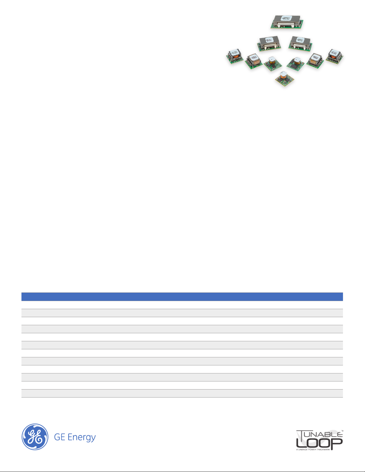
GE Energy POL power converters provide small, ecient, and reliable power electronics modules for FPGAs and DSPs.
Our high-density POL (point-of-load) DC-DC converters provide a cost-eective solution to power silicon that includes
DSP Core and I/O requirements ranging from 0.6V to 5V.
Our standards-based, modular solutions deliver a lower total system cost; provide three times better transient response,
have a smaller footprint; and are easier to implement than discrete solutions.
• Accelerate time to market
• Reduce risk of design errors
• Scalable oering from 2 – 250 Amps (5 x 50A)
• Digital and analog design exibility
• Leading power density
• Pre-characterized electrical and thermal performance
• International safety approvals
• EZ-Sequence™ feature for sequencing management
• Adaptive Voltage Scaling (AVS) reduces
power consumption
• Proven reliability >3 billion hours MTBF
• Reduced BOM - 1 part Vs. 15 to 40
• Synchronization and Power Good features
• Wide input voltage range 3.0V to 14.4V
• High frequency switching
• Tunable Loop™ feature reduces discrete components
(external input and output capacitor requirements)
Leading Density at Low Cost
GE Energy Tunable Loop™ products ensure low cost implementation of board mounted power in standards-based
DOSA footprints.
Product Family Output Models Communication Input Voltage Output Voltage Output Current Eciency Dimensions
PicoDLynx™ PDT003 Digital PMBus™ 3.0-14.4V 0.45-5.5V 3A 94% 12.2 x 12.2 x 6.25 mm
PicoDLynx™ PDT006 Digital PMBus™ 3.0-14.4V 0.45-5.5V 6A 94% 12.2 x 12.2 x 7.25 mm
PicoDLynx™ PDT012 Digital PMBus™ 3.0-14.4V 0.45-5.50V 12A 96% 12.2 x 12.2 x 8.5 mm
MicroDLynx™ UDT020 Digital PMBus™ 3.0-14.4V 0.45-5.50V 20A 96% 20.3 x 11.4 x 8.5 mm
MegaDLynx™ MDT040 Digital PMBus™ 4.5-14.4V 0.45 to 2.0V 40A 94% 33 x 13.5 x 10.9 mm
PicoDLynx™ PVX003 Analog 3.0-14.4V 0.6-5.5V 3A 94% 12.2 x 12.2 X 6.25 mm
PicoDLynx™ PVX006 Analog 3.0-14.4V 0.6-5.5V 6A 94% 12.2 x 12.2 X 7.25 mm
PicoDLynx™ PVX012 Analog 3.0-14.4V 0.60-5.5V 12A 96% 12.2 x 12.2 X 8.5 mm
MicroDLynx™ UVT020 Analog 3.0-14.4V 0.60-5.5V 20A 96% 20.3 x 11.4 x 8.5 mm
MegaDLynx™ MVT040 Analog 4.5-14.4V 0.6 -2.0V 40A 94% 33 x 13.5 x 10.9 mm
PicoTLynx™ APXS002 Analog 3.0-14.0V 0.60-5.50V 2A 96% 12.2 x 12.2 x 6.25 mm
MegaTLynx™ APTS030 Analog 6.0 – 14.0V 0.8V - 2.75V 30A 96% 33 x 13.5 x 10 mm
GigaTLynx™ APTS050 Analog 4.5-14.0V 0.60-2.0V 50A 95% 33 x 22.9 x 10 mm
Altera FPGA01/12
© 2012 General Electric Company. All rights reserved.
Page 2

Altera Power Requirement by Part Number
Stratix®, Cyclone®, MAX®, Arria™ are registered trademarks of the Altera® Corporation.
Always refer to manufacturer’s specication for correct and up-to-date power information.
Stratix® V GX , GS, GT - Core Voltage: Module Output 0.85V to 3.0V
Input V 0 to 2 Amp 0 to 3 Amp 3 to 6 Amp 6 to 12 Amp 12 to 20 Amp 20 to 30 Amps 30 to 40 Amps (2Vo max) 40 to 50A(2Vo max)
3-14/14.4V APXS002A0X-SRZ PDT/PVX003A0X3-SRZ PDT/PVX006A0X3-SRZ PDT/PVX012A0X3-SRZ UDT/UVT020A0X3-SRZ
4.5-14/14.4V MDT/MVT040A0X3-SRZ* APTS050A0X3-SRPHZ*1
6-14V APTS030A0X3-SRPHZ3
Stratix® V GX, GS, GT - I/O Voltage: Module Output 0.85V to 3.0V
Input V 0 to 2 Amp 0 to 3 Amp 3 to 6 Amp 6 to 12 Amp 12 to 20 Amp 20 to 30 Amps 30 to 40 Amps (2Vo max) 40 to 50A(2Vo max)
3-14/14.4V APXS002A0X-SRZ PDT/PVX003A0X3-SRZ PDT/PVX006A0X3-SRZ PDT/PVX012A0X3-SRZ UDT/UVT020A0X3-SRZ
4.5-14/14.4V MDT/MVT040A0X3-SRZ* APTS050A0X3-SRPHZ*1
6-14V APTS030A0X3-SRPHZ3
Stratix® IV GX - IV E - IV GT - Core Voltage: Module Output 0.9V to 2.5V
Input V 0 to 2 Amp 0 to 3 Amp 3 to 6 Amp 6 to 12 Amp 12 to 20 Amp 20 to 30 Amps 30 to 40 Amps (2Vo max) 40 to 50A(2Vo max)
3-14/14.4V APXS002A0X-SRZ PDT/PVX003A0X3-SRZ PDT/PVX006A0X3-SRZ PDT/PVX012A0X3-SRZ UDT/UVT020A0X3-SRZ
4.5-14/14.4V MDT/MVT040A0X3-SRZ* APTS050A0X3-SRPHZ*1
6-14V APTS030A0X3-SRPHZ3
Stratix® IV GX - IV E - IV GT - I/O Voltage: Module Output 0.9V to 3.0V
Input V 0 to 2 Amp 0 to 3 Amp 3 to 6 Amp 6 to 12 Amp 12 to 20 Amp 20 to 30 Amps 30 to 40 Amps (2Vo max) 40 to 50A(2Vo max)
3-14/14.4V APXS002A0X-SRZ PDT/PVX003A0X3-SRZ PDT/PVX006A0X3-SRZ PDT/PVX012A0X3-SRZ UDT/UVT020A0X3-SRZ
4.5-14/14.4V MDT/MVT040A0X3-SRZ* APTS050A0X3-SRPHZ*1
6-14V APTS030A0X3-SRPHZ
Hardcopy® IV E - 1V GX -
Input V 0 to 2 Amp 0 to 3 Amp 3 to 6 Amp 6 to 12 Amp 12 to 20 Amp 20 to 30 Amps 30 to 40 Amps (2Vo max) 40 to 50A(2Vo max)
3-14/14.4V APXS002A0X-SRZ PDT/PVX003A0X3-SRZ PDT/PVX006A0X3-SRZ PDT/PVX012A0X3-SRZ UDT/UVT020A0X3-SRZ
4.5-14/14.4V MDT/MVT040A0X3-SRZ* APTS050A0X3-SRPHZ*1
6-14V APTS030A0X3-SRPHZ
Core Voltage: Module Output - 0.9V
Hardcopy® IV E - I/O voltage : Module Output 1.2V to 3.0V
Input V 0 to 2 Amp 0 to 3 Amp 3 to 6 Amp 6 to 12 Amp 12 to 20 Amp 20 to 30 Amps 30 to 40 Amps (2Vo max) 40 to 50A(2Vo max)
3-14/14.4V APXS002A0X-SRZ PDT/PVX003A0X3-SRZ PDT/PVX006A0X3-SRZ PDT/PVX012A0X3-SRZ UDT/UVT020A0X3-SRZ
4.5-14/14.4V MDT/MVT040A0X3-SRZ* APTS050A0X3-SRPHZ*1
6-14V APTS030A0X3-SRPHZ
Hardcopy® IV GX - I/O Voltage: Module Output 0.9V to 3.0V
Input V 0 to 2 Amp 0 to 3 Amp 3 to 6 Amp 6 to 12 Amp 12 to 20 Amp 20 to 30 Amps 30 to 40 Amps (2Vo max) 40 to 50A(2Vo max)
3-14/14.4V APXS002A0X-SRZ PDT/PVX003A0X3-SRZ PDT/PVX006A0X3-SRZ PDT/PVX012A0X3-SRZ UDT/UVT020A0X3-SRZ
4.5-14/14.4V MDT/MVT040A0X3-SRZ* APTS050A0X3-SRPHZ*1
6-14V APTS030A0X3-SRPHZ
Notes: * These module can only deliver a max of 2Vout
1. Output currents above 50A are also achieved by paralleling multiple APTS050 devices. See specication for details.
All parts are non-isolated buck regulators. As such, Vin must exceed programmed Vout. See individual specications for details.
Stratix®, Cyclone®, MAX®, Arria™ are registered trademarks of the Altera® Corporation
Page 2
Altera FPGA01/12
© 2012 General Electric Company. All rights reserved.
Page 3

Altera Power Requirement by Part Number
Stratix®, Cyclone®, MAX®, Arria™ are registered trademarks of the Altera® Corporation.
Always refer to manufacturer’s specication for correct and up-to-date power information.
Arria™V GX, GT -
Input V 0 to 2 Amp 0 to 3 Amp 3 to 6 Amp 6 to 12 Amp 12 to 20 Amp 20 to 30 Amps 30 to 40 Amps (2Vo max) 40 to 50A(2Vo max)
3-14/14.4V APXS002A0X-SRZ PDT/PVX003A0X3-SRZ PDT/PVX006A0X3-SRZ PDT/PVX012A0X3-SRZ UDT/UVT020A0X3-SRZ
4.5-14/14.4V MDT/MVT040A0X3-SRZ* APTS050A0X3-SRPHZ*1
6-14V APTS030A0X3-SRPHZ3
Core Voltage: Module Output 1.1V to 3.3V
Arria™V GX, GT - I/O Voltage: Module Output 1.1 to 2.5V
Input V 0 to 2 Amp 0 to 3 Amp 3 to 6 Amp 6 to 12 Amp 12 to 20 Amp 20 to 30 Amps 30 to 40 Amps (2Vo max) 40 to 50A(2Vo max)
3-14/14.4V APXS002A0X-SRZ PDT/PVX003A0X3-SRZ PDT/PVX006A0X3-SRZ PDT/PVX012A0X3-SRZ UDT/UVT020A0X3-SRZ
4.5-14/14.4V MDT/MVT040A0X3-SRZ* APTS050A0X3-SRPHZ*1
6-14V APTS030A0X3-SRPHZ3
Arria™ II GX - Core Voltage: Module Output 0.9V to 3.3V
Input V 0 to 2 Amp 0 to 3 Amp 3 to 6 Amp 6 to 12 Amp 12 to 20 Amp 20 to 30 Amps 30 to 40 Amps (2Vo max) 40 to 50A(2Vo max)
3-14/14.4V APXS002A0X-SRZ PDT/PVX003A0X3-SRZ PDT/PVX006A0X3-SRZ PDT/PVX012A0X3-SRZ UDT/UVT020A0X3-SRZ
4.5-14/14.4V MDT/MVT040A0X3-SRZ* APTS050A0X3-SRPHZ*1
6-14V APTS030A0X3-SRPHZ3
Arria™ II GX - Core Voltage: Module Output 0.6V to 2.5V
Input V 0 to 2 Amp 0 to 3 Amp 3 to 6 Amp 6 to 12 Amp 12 to 20 Amp 20 to 30 Amps 30 to 40 Amps (2Vo max) 40 to 50A(2Vo max)
3-14/14.4V APXS002A0X-SRZ PDT/PVX003A0X3-SRZ PDT/PVX006A0X3-SRZ PDT/PVX012A0X3-SRZ UDT/UVT020A0X3-SRZ
4.5-14/14.4V MDT/MVT040A0X3-SRZ* APTS050A0X3-SRPHZ*1
6-14V APTS030A0X3-SRPHZ3
MAX® V Series - System and I/O Voltage: Module Output 1.2V to 4.0V
Input V 0 to 2 Amp 0 to 3 Amp 3 to 6 Amp 6 to 12 Amp 12 to 20 Amp 20 to 30 Amps 30 to 40 Amps (2Vo max) 40 to 50A(2Vo max)
3-14/14.4V APXS002A0X-SRZ PDT/PVX003A0X3-SRZ PDT/PVX006A0X3-SRZ PDT/PVX012A0X3-SRZ UDT/UVT020A0X3-SRZ
4.5-14/14.4V MDT/MVT040A0X3-SRZ* APTS050A0X3-SRPHZ*1
6-14V APTS030A0X3-SRPHZ3
Cyclone® IV E, GX - Core Voltage: Module Output 1.2V to 3.3V
Input V 0 to 2 Amp 0 to 3 Amp 3 to 6 Amp 6 to 12 Amp 12 to 20 Amp 20 to 30 Amps 30 to 40 Amps (2Vo max) 40 to 50A(2Vo max)
3-14/14.4V APXS002A0X-SRZ PDT/PVX003A0X3-SRZ PDT/PVX006A0X3-SRZ PDT/PVX012A0X3-SRZ UDT/UVT020A0X3-SRZ
4.5-14/14.4V MDT/MVT040A0X3-SRZ* APTS050A0X3-SRPHZ*1
6-14V APTS030A0X3-SRPHZ3
Cyclone® IV E, GX - I/O Voltage: Module Output 1.0V to 3.3V
Input V 0 to 2 Amp 0 to 3 Amp 3 to 6 Amp 6 to 12 Amp 12 to 20 Amp 20 to 30 Amps 30 to 40 Amps (2Vo max) 40 to 50A(2Vo max)
3-14/14.4V APXS002A0X-SRZ PDT/PVX003A0X3-SRZ PDT/PVX006A0X3-SRZ PDT/PVX012A0X3-SRZ UDT/UVT020A0X3-SRZ
4.5-14/14.4V MDT/MVT040A0X3-SRZ* APTS050A0X3-SRPHZ*1
6-14V APTS030A0X3-SRPHZ3
Notes: * These module can only deliver a max of 2Vout
1. Output currents above 50A are also achieved by paralleling multiple APTS050 devices. See specication for details.
All parts are non-isolated buck regulators. As such, Vin must exceed programmed Vout. See individual specications for details.
Stratix®, Cyclone®, MAX®, Arria™ are registered trademarks of the Altera® Corporation
Page 3
Altera FPGA01/12
© 2012 General Electric Company. All rights reserved.
Page 4

GE Energy
Digital Power Insight™ Tools
The DPI kit provides power engineers with a user interface
that delivers control exibility over their digital products.
The DPI™ GUI communicates with PMBus™ enabled products, specically
DLynx POLs, via a USB to I2C adapter. The software features continuous
monitoring (polling) of input voltage, output voltage and current, as well as
module status. Status changes are automatically time stamped and logged
by the software and are easily exported. A Command Line Interface (CLI) is also
available for a more in-depth analysis of the transmitted data across the I2C
bus. The CLI is a useful tool for creating and executing user-dened routines and
scripts, as well as the logging of data for future review or plotting.
In addition to its monitoring capabilities, designers can use the DPI kit to
congure and recongure voltages, thresholds, warnings, and settings for
individual power modules. All nal values for the conguration specs can be
saved. Engineers can also use the software’s built-in auto-detect functionality
to identify modules on the I2C bus.
The software enables engineers to create custom conguration les and to
ne-tune and optimize a variety of parameters to ensure the highest levels of
performance and eciency. The DPI Software Tool Set is distributed as a zip le
that can be downloaded from a link on the GE Energy website.
http://www.digitalpowerinsight.com
Note: The red line must be on the
left hand side of the ribbon cable
to ensure proper keying
2
3
1
Contact Us
For more information, call us toll free
at +1 888 546 3243, or +1 972 244 9288
and visit us on the web at
www.ge.com/powerelectronics
Altera FPGA01/12
© 2012 General Electric Company. All rights reserved.
 Loading...