

Page 1
Technology for the Digital World.
208 Vac PDU
File#: E238017
User manual
Power Distribution Unit
Power Distribution Unit
For Use with 208 Vac UPS Systems
ver 1.2 - US
Page 2
USER MANUAL
Power Distribution Unit
For Use with 208 Vac UPS Systems
The 208V Power Distribution Unit, provides both 208VAC and 120VAC output
connectivity for 208 Vac Input UPS systems.
Please keep this manual in a safe place for future reference and carefully read the
important safety instructions in chapter 1 before installation and start-up of the
UPS
.
202 00021 01 1 User manual rev date 8-16--05
Page 3

CONTENTS
1 IMPORTANT SAFETY INSTRUCTIONS..............................................3
1.1 Save these instructions
1.2 General
1.3 Installation
1.4 Transportation
2 INSTALLATION.....................................................................................4
2.1 Package contents
2.2 Location
2.3 Rear panel
2.4 Installation
2.4.1 Reference UPS User Manual
2.4.2 Connecting the PDU
3 SPECIFICATIONS.................................................................................7
202 00021 01 2 User manual rev date 8-16--05
Page 4

Before attempting to install and start up the UPS, carefully read this
All servicing must be done by qualified personnel. Do not attempt
By opening or removing covers you run the risk of
1.1 Save these instructions
1 - Important Safety Instructions
This manual contains important instructions for the 208V PDU that should be followed
during installation and maintenance of the UPS/PDU system.
manual. Keep this manual next to the PDU for future references.
to service the PDU unless you have had proper training.
WARNING:
exposure to dangerous voltages !
1.2 General
1.3 Installation
1.4 Transportation
CAUTION: RISK OF ELECTRIC SHOCK.
The appliance outlets may be electrically live when installed with a UPS, even when
the UPS is disconnected from the utility supply. Dangerous voltages may be present
during battery operation.
Do not open the unit, there are no user serviceable parts inside.
The appliance outlets shall be installed near the equipment and shall be easily
accessible
The unit should be installed by service personnel.
To reduce the risk of electric shock, install the PDU in a temperature and humidity
controlled indoor area free of conductive contaminants.
Ambient temperature must not exceed 40°C (104°F).
It is important that the unit has adequate ventilation. Maintain air movement around
and through the unit. Do not block the air vents.
Avoid placing the unit in direct sunlight or near heat sources.
Avoid spilling liquids on or dropping any foreign object into the PDU.
Do not plug a laser printer or household appliances such as electric heaters or
vacuum cleaners into the PDU. The PDU output is intended to be used only for
electronic loads such as computers and telecommunications equipment.
The unit should be operated by properly trained personnel.
No liability can be accepted for any transport damage when the equipment is
shipped in non-original packaging.
202 00021 01 3 User manual rev date 8-16--05
Page 5

2.1 Package contents
2 - Installation
The packing box contains a 208V PDU, and this manual. Carefully inspect the packing box and
its contents. If any damage is visible please immediately notify the carrier and/or dealer.
2.2 Location
Please refer to section 1.3 of ‘IMPORTANT SAFETY INSTRUCTIONS’
2.3 Rear panel
1
1
1
2
2
2
3
3
3
4
4
4
5
5
5
PDU620T and PDU630T
PDU620T and PDU630T
1 120VAC Output Breaker
Fig. 2.1 Rear panel
4 208VAC Output Receptacles
Over-current Protection Breaker for
120VAC, L5-15 Output Receptacles
(10 Amp)
2 120VAC Output Receptacles
120VAC L5-15 Output Receptacles
to Connect 120VAC Load to PDU
3 208VAC Input Breaker
5 208VAC Input Cord
Over-current Protection Breaker for
208VAC Input (L6-20P Input Plug =
20 Amp; L6-30P Input Plug = 30
Amp)
208VAC L6-xxR Output Receptacles
to Connect 208VAC Load to PDU.
(L6-20R Output Receptacle = 20
Amp; L6-30R Output Receptacle =
30 Amp)
208VAC L6-xxP Input Cord to
Connect 208VAC Input from the
UPS. (L6-20P Input Plug for L6-20
PDU; L6-30P Input Plug for L6-30
PDU)
202 00021 01 4 User manual rev date 8-16--05
Page 6

Front View
Rear View
2.4 Installation
The unit should be installed by service personnel.
2.4.1 Before Installing the 208V PDU, reference the UPS User Manual for proper
2.4.2 Connecting the PDU
installation and operation of the UPS system.
1. Insure that the UPS Output is off before installing the PDU. (Remember, the UPS
output may still be LIVE even when disconnected from utility power) refer to the
UPS User Manual for procedure to turn off all outputs.
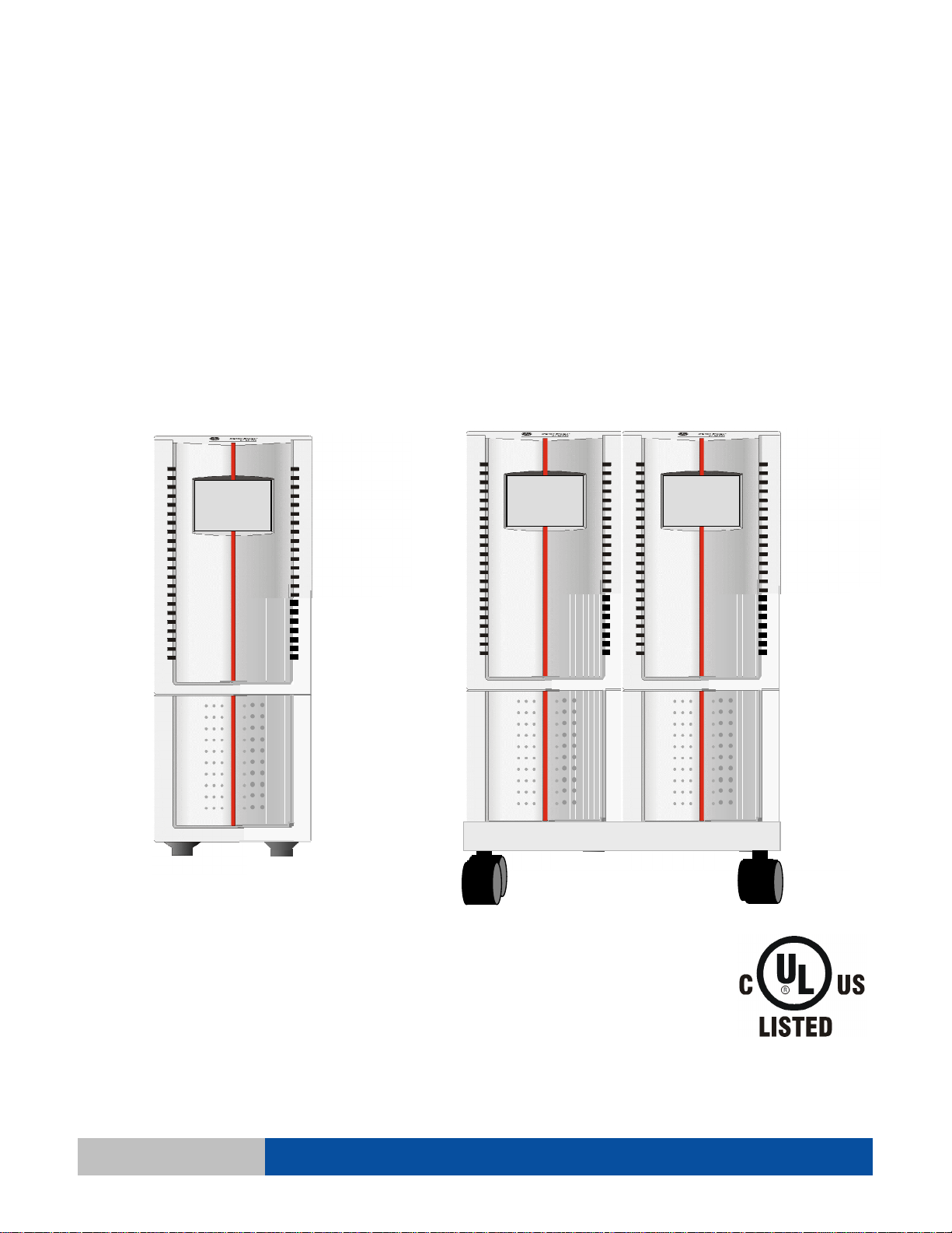
2. Install the PDU and UPS units on the GT Tray with the PDU on the right hand side of
the UPS when facing the units. (as shown in Fig. 1 below)
IMPORTANT:
Insure that the ventilation openings on the left side of the UPS and the right side of the
PDU are always open and free from obstruction.
3. Plug the PDU 208VAC input plug into the locking 208VAC output receptacle of the
UPS and twist to lock. (see Fig. 1 Rear View)
UPS
UPSUPS
PDU
PDUPDU
Fig. 1
Fig. 1
PDU UPS
PDU UPS
202 00021 01 5 User manual rev date 8-16--05
Page 7

4. Plug the equipment that you wish to power into the output receptacles of the PDU.
5. Install and power-up the UPS as instructed in the UPS User Manual supplied with
the UPS system.
6. The installed UPS/PDU system should be similar to the system shown in Fig. 2.
Install Equipment Plug into
Install Equipment Plug into
any of the L5-15 or L6-**
any of the L5-15 or L6-**
Output Receptacles
Output Receptacles
Utility
Utility
Supply
Supply
Supported
Supported
Equipment
Equipment
Fig. 2
Fig. 2
7. The PDU now supplies both 120VAC and 208VAC outputs from the single 208VAC
output of the UPS.
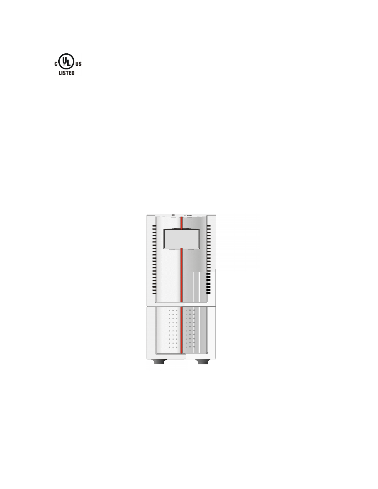
NOTE: Using the 208V PDU without the tray assembly
To secure a stable placing of the 208V PDU as a free standing unit without the
GT tray assembly, it is advised to set up the PDU with supporting stands (not
included in delivery) as shown:
Supporting stands
(not included)
202 00021 01 6 User manual rev date 8-16--05
Page 8

3 - Specifications
PDU Model PDU-01-112-GT PDU-02-113-GT PDU-03-112-GT PDU-04-113-GT
Rated Voltage 208VAC 208VAC 208VAC 208VAC
Frequency 50/60 Hz 50/60 Hz 50/60 Hz 50/60 Hz
Input
Max. Current 20 A 30A 20 A 30A
Plug Type L6-20P L6-30P L6-20P L6-30P
Cord Length 12 in. (30.48 cm) 5 ft. (1.5 m)
Voltage 120VAC 120VAC 120VAC 120VAC
Output
120VAC
Frequency 50/60 Hz 50/60 Hz 50/60 Hz 50/60 Hz
Max. Current 10 A (total) 10 A (total) 10 A (total) 10 A (total)
Receptacle
2x 5-15 Duplex 2x 5-15 Duplex 2x 5-15 Duplex 2x 5-15 Duplex
Type
Voltage 208VAC 208VAC 208VAC 208VAC
Output
208VAC
Frequency 50/60 Hz 50/60 Hz 50/60 Hz 50/60 Hz
Max. Current 20 A 30 A 20 A 30 A
Receptacle
L6-20R L6-30R L6-20R L6-30R
Type
Output Total
Environment
Total Max.
Current
24 A
14A @ 208VAC
10A @ 120VAC
34 A
24A @ 208VAC
10A @ 120VAC
Operating
Temperature
°C (32~104°F)
0~40
24 A
14A @ 208VAC
10A @ 120VAC
24A @ 208VAC
10A @ 120VAC
34 A
Humidity 0%~90% (non-condensing)
Safety
Approval
Appearance
Safety
Dimensions
×D×
H)
(W
Weight
UL/cUL
140x366x242 mm
5.5x14.4x9.5 inch
20.86 kg
46 lbs
202 00021 01 7 User manual rev date 8-16--05
 Loading...