

Page 1

Galaxy Power System 4812/24
(GPS 4812/24)
H569-436
User’s Guide
Select Code 167-792-161
Comcode 108313057
Issue 9
Januray 2008
Page 2

Page 3

User’s Guide
Select Code 167-792-161
Comcode 108313057
Issue 9
Januray 2008
Galaxy Power System 4812/24
(GPS 4812/24)
H569-436
Notice:
The information, specifications, and procedures in this manual are
subject to change without notice. Lineage Power assumes no
responsibility for any errors that may appear in this document.
© 2008 Lineage Power
All International Rights Reserved
Printed in U.S.A.
Page 4

Page 5

Galaxy Power System 4812/24
Table of Contents
1 Introduction
GPS 4812/24 1-1
Overview 1-1
Illustrations 1-1
Customer Service Contacts 1-4
Customer Service, Technical Support, Product Repair and
Return, and Warranty Service 1-4
Customer Training 1-4
Downloads and Software 1-4
2 System Description
Overview 2-1
Block Diagram 2-1
System Components 2-2
Architecture 2-3
Configurations 2-3
Illustrations 2-3
3 Galaxy Controllers
Overview 3-1
Introduction 3-1
Galaxy Millennium Controller 3-2
Design 3-2
User Interface and Display 3-2
Default Display 3-2
LEDs 3-3
Test Jacks 3-3
Pushbutton Keys 3-4
Access Panel 3-4
Galaxy Vector Controller 3-5
Design 3-5
User Interface and Display 3-5
Default Display 3-5
LEDs 3-5
Pushbutton Keys 3-6
Access Panel 3-6
Reference Material 3-7
Controller Product Manuals 3-7
RPM System Product Manual 3-7
Issue 9 Januray 2008 Table of Contents - 1
Page 6

Galaxy Power System 4812/24
4 Rectifiers
596 Series A and D 4-1
Overview 4-1
Front Panel Display 4-1
Power Switch 4-1
Status Indicators 4-1
Current Display 4-2
Lamp Test 4-2
Features 4-3
Output Current “Walk-in” 4-3
Output Protection 4-3
Electronic Current Limit 4-3
High Voltage Shutdown (HVSD) 4-3
Restart 4-3
Fan Alarm and Control 4-3
Thermal Alarm 4-3
Autonomous Operation 4-3
Controller Communications Alarm 4-3
Connectorized 4-4
“Forced” Load Sharing 4-4
5 AC Input Panels
Overview 5-1
AC Service 5-1
Illustrations 5-1
6 Battery Connection Panels
Overview 6-1
Function 6-1
Illustrations 6-1
7 DC Distribution Panels
Overview 7-1
Function 7-1
Illustrations 7-1
2 - Table of Contents Issue 9 Januray 2008
Page 7

Galaxy Power System 4812/24
8 Circuit Boards
Overview 8-1
Function 8-1
Terminal Boards 8-1
Alarm Boards 8-1
Alarm/Terminal Boards 8-1
BLJ Terminal Board 8-1
Overview, continued 8-2
Contactor Control Board 8-2
Millennium Systems 8-2
Vector Systems 8-2
9 Specifications
GPS 4812/24 9-1
Rectifier 9-3
AC Input Panels 9-5
Applications and Cross Reference 9-5
Battery Connection Panels 9-6
DC Distribution Panels 9-7
10 Safety
11 Maintenance and Replacement
Requirements 11-1
System 11-1
Batteries 11-1
Rectifiers 11-1
Rectifier Fan Assembly 11-2
Replacement Procedures 11-3
Installing or Replacing a Rectifier 11-3
Replacing a Rectifier Fan Assembly 11-5
Replacement Parts 11-6
System 11-6
Millennium Controller Circuit Boards 11-7
Vector Controller Circuit Boards 11-7
Additional Ordering Information 11-8
Documentation 11-8
Software 11-8
Issue 9 Januray 2008 Table of Contents - 3
Page 8

Galaxy Power System 4812/24
12 Troubleshooting Preparations
Preliminary 12-1
Introduction 12-1
Safety 12-1
Tools 12-1
Troubleshooting Procedure 12-2
Purpose 12-2
Cabinet Alarm 12-2
System Status 12-3
Alarms Menu 12-3
Troubleshooting Tables 12-4
Identifying Problems 12-5
Reference Figures 12-6
Figure Numbers and Titles 12-6
Millennium Controller 12-7
Vector Controller 12-9
Rectifiers 12-10
Low Voltage Battery Disconnect 12-11
AC Input 12-12
DC Distribution 12-13
Low Voltage Load Disconnect 12-14
13 Troubleshooting Millennium Systems
Introduction 13-1
In This Section 13-1
Preparation 13-1
Technical Assistance 13-1
Troubleshooting Tables 13-2
Organization 13-2
Table Reference 13-2
Millennium Display Reference 13-2
AC System Alarm LED 13-3
Battery Alarm LED 13-4
Controller Alarm LED 13-6
Distribution Alarm LED 13-11
Rectifier Alarm LED 13-12
Battery on Discharge and Remote Modules Alarm LEDs,
or No LED 13-16
4 - Table of Contents Issue 9 Januray 2008
Page 9

Galaxy Power System 4812/24
14 Troubleshooting Vector Systems
Introduction 14-1
In This Section 14-1
Preparation 14-1
Technical Assistance 14-1
Troubleshooting Tables 14-2
Organization 14-2
Table Reference 14-2
Vector Display Reference 14-3
AC Alarms 14-4
Battery Alarms 14-5
Controller Alarms 14-6
Distribution Alarms 14-7
Rectifier Related Alarms 14-8
Miscellaneous Alarms 14-11
15 Product Warranty
Issue 9 Januray 2008 Table of Contents - 5
Page 10

Page 11

Galaxy Power System 4812/24
List of Figures
Figure 1-1: GPS 4812/24 Half Height Initial
Cabinet (with Battery Stand) 1-2
Figure 1-2: GPS 4812/24 Full Height Initial Cabinet 1-3
Figure 2-1: Block Diagram of the GPS 4812/24 2-1
Figure 2-2: Schematic of Half Height Cabinet 2-4
Figure 2-3: Schematic of Full Height Cabinet 2-5
Figure 2-4: Schematic of Two-cabinet System Architecture 2-6
Figure 2-5: Half Height GPS 4812/24 with Door Open 2-7
Figure 2-6: Full Height GPS 4812/24 with Door Open 2-8
Figure 3-1: Galaxy Millennium Controller Front Panel 3-2
Figure 3-2: Galaxy Vector Controller Front Panel 3-5
Figure 4-1: Rectifier Front Panel 4-2
Figure 5-1: AC Input Circuit Breaker Panels 5-2
Figure 5-1: AC Input Terminal Strip Panels 5-3
Figure 6-1: H569-436 G30 (ED83143-31 G32)
Battery Connection Panel 6-2
Figure 6-2: H569-436 G31 (ED83143-31 G31)
Battery Connection Panel 6-2
Figure 6-3: H569-436 G34 (ED83143-31 G41)
Battery Connection Panel 6-3
Figure 6-4: H569-435 G35 (ED83143-31 G42)
Battery Connection Panel 6-3
Figure 6-5: H569-436 G36H (ED83143-31 G33)
Battery Connection Panel 6-4
Figure 6-6: H569-436 G37F/38F (ED83143-31 G60/61)
Battery (OLE) Connection Panel 6-4
Issue 9 Januray 2008 List of Figures - 1
Page 12

Galaxy Power System 4812/24
Figure 6-7: H569-436 G80/81/82 (ED83143-31 G31/43)
Battery Connection Panel 6-5
Figure 6-8: H569-436 G84H (ED83143-31 G34)
Battery Connection Panel 6-6
Figure 6-9: H569-436 G85F (ED83143-31 G35)
Battery Connection Panel 6-6
Figure 6-10: H569-436 G86/87 (ED83143-31 G63/64)
Battery Connection Panel 6-7
Figure 7-1: H569-436 G40/50 (ED83143-31 G11)
DC Distribution Panel 7-2
Figure 7-2: H569-436 G41/51 (ED83143-31 G12)
DC Distribution Panel 7-2
Figure 7-3: H569-436 G42 (ED83143-31 G2)
DC Distribution Panel 7-3
Figure 7-4: H569-436 G43 (ED83143-31 G1)
DC Distribution Panel 7-3
Figure 7-5: H569-436 G44 (ED83143-31 G5)
DC Distribution Panel 7-4
Figure 7-6: H569-436 G46 (ED83143-31 G15)
DC Distribution Panel 7-4
Figure 7-7: H569-436 G52 (ED83143-31 G53)
DC Distribution Panel 7-5
Figure 7-8: H569-436 G53 (ED83143-31 G55)
DC Distribution Panel 7-5
Figure 7-9: H569-436 G60/61/65/66 (ED83143-31 G71)
DC Distribution Panel 7-6
Figure 7-10: H569-436 G67 (ED83143-31 G22)
DC Distribution Panel 7-6
Figure 7-11: H569-436 G68 (ED83143-31 G21)
DC Distribution Panel 7-7
Figure 9-1: Output Current vs. Temperature 9-5
Figure 11-1: Detail of Rectifier Position 11-3
Figure 12-1: Location of Cabinet Alarm 12-2
2 - List of Figures Issue 9 Januray 2008
Page 13

Galaxy Power System 4812/24
Figure 12-2: Millennium Controller Display 12-8
Figure 12-3: Location of Millennium Controller Fuses
and Boards 12-8
Figure 12-4: Vector Controller Display 12-9
Figure 12-5: Location of Vector Controller Fuses
and Boards 12-9
Figure 12-6: Rectifier Display 12-10
Figure 12-7: Low Voltage Battery Disconnect Contactor
Control Switches 12-11
Figure 12-8: Detail of AC Input Panel and Rectifier Shelf 12-12
Figure 12-9: Detail of DC Distribution Panel 12-13
Figure 12-10: Low Voltage Load Disconnect Contactor
Control Switches 12-14
Issue 9 Januray 2008 List of Figures - 3
Page 14

Page 15

Galaxy Power System 4812/24
List of Tables
Table 9-A: Galaxy Power System 4812/24 Specifications 9-1
Table 9-B: Rectifier Specifications 9-3
Table 9-C: AC Input Panels 9-5
Table 9-D: Battery Connection Panels 9-6
Table 9-E: Battery Connection Panels 9-7
Table 11-A: GPS 4812/24 System Replacement Parts 11-6
Table 11-B: Galaxy Millennium Controller Circuit Boards 11-7
Table 11-C: Galaxy Vector Controller
Circuit Boards and Temperature Module 11-7
Table 11-D: Product Documentation 11-8
Table 13-A: AC Alarms 13-3
Table 13-B: Battery Alarms 13-4
Table 13-C: Controller Alarms 13-6
Table 13-D: Distribution Alarms 13-11
Table 13-E: Rectifier Related Alarms 13-12
Table 13-F: Miscellaneous Alarms 13-16
Table 14-A: AC Alarms 14-4
Table 14-B: Battery Alarms 14-5
Table 14-C: Controller Alarms 14-6
Table 14-D: Distribution Alarms 14-7
Table 14-E: Rectifier Related Alarms 14-8
Table 14-F: Miscellaneous Alarms 14-11
Issue 9 Januray 2008 List of Tables - 1
Page 16

Page 17

Galaxy Power System 4812/24
1 Introduction
GPS 4812/24
Overview Lineage Power developed the Galaxy Power System (GPS) 4812/24 to
support -48 volt telecommunications powering solutions in worldwide
markets. The GPS 4812/24 combines 55-ampere and 110-ampere,
fan-cooled, switchmode rectifiers, microprocessor control technologies,
battery and load disconnect/reconnect options, and a comprehensive
line of fuse and circuit breaker dc distribution options in a modular
front-access design. This modularity ensures easy access, simplified
installation and maintenance, and allows the system to expand in
capacity and features as power needs grow.
With 7,040-ampere maximum capacity, distribution flexibility, and
universal ac input capability, the GPS 4812/24 supports switching,
transmission, and wireless applications in central office locations and
environmentally controlled remote sites (huts or vaults).
The main emphasis of this manual is to provide a general product
description that will familiarize the user with the main components of
the system and to provide guidelines for the basic maintenance of this
Galaxy Power System.
Note Prior to Issue 6 of this manual, the GPS 4812/24 cabinet had a metal
door and the Galaxy Vector Controller consisted of a BIC3 board. For
information on these systems, see Issue 5 of this manual.
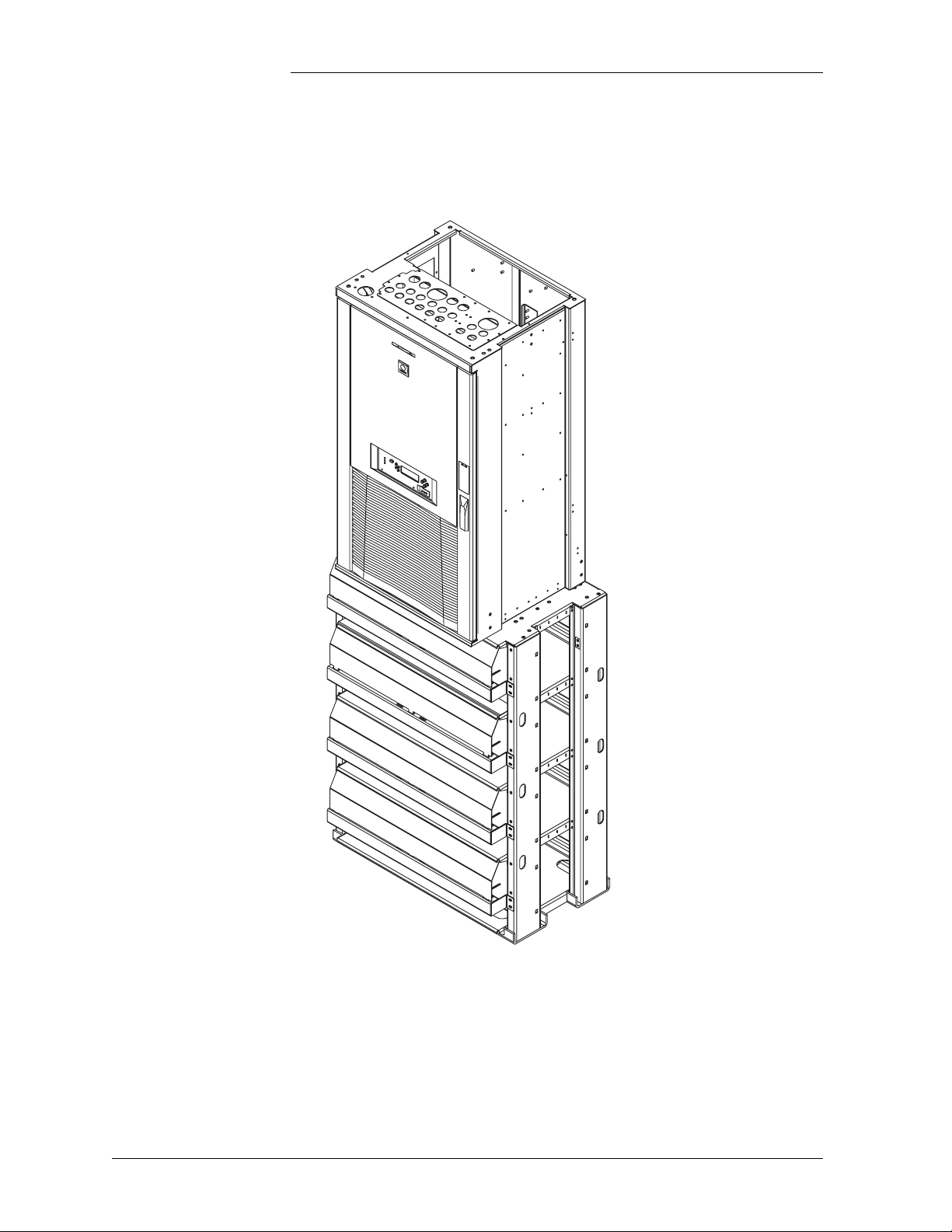
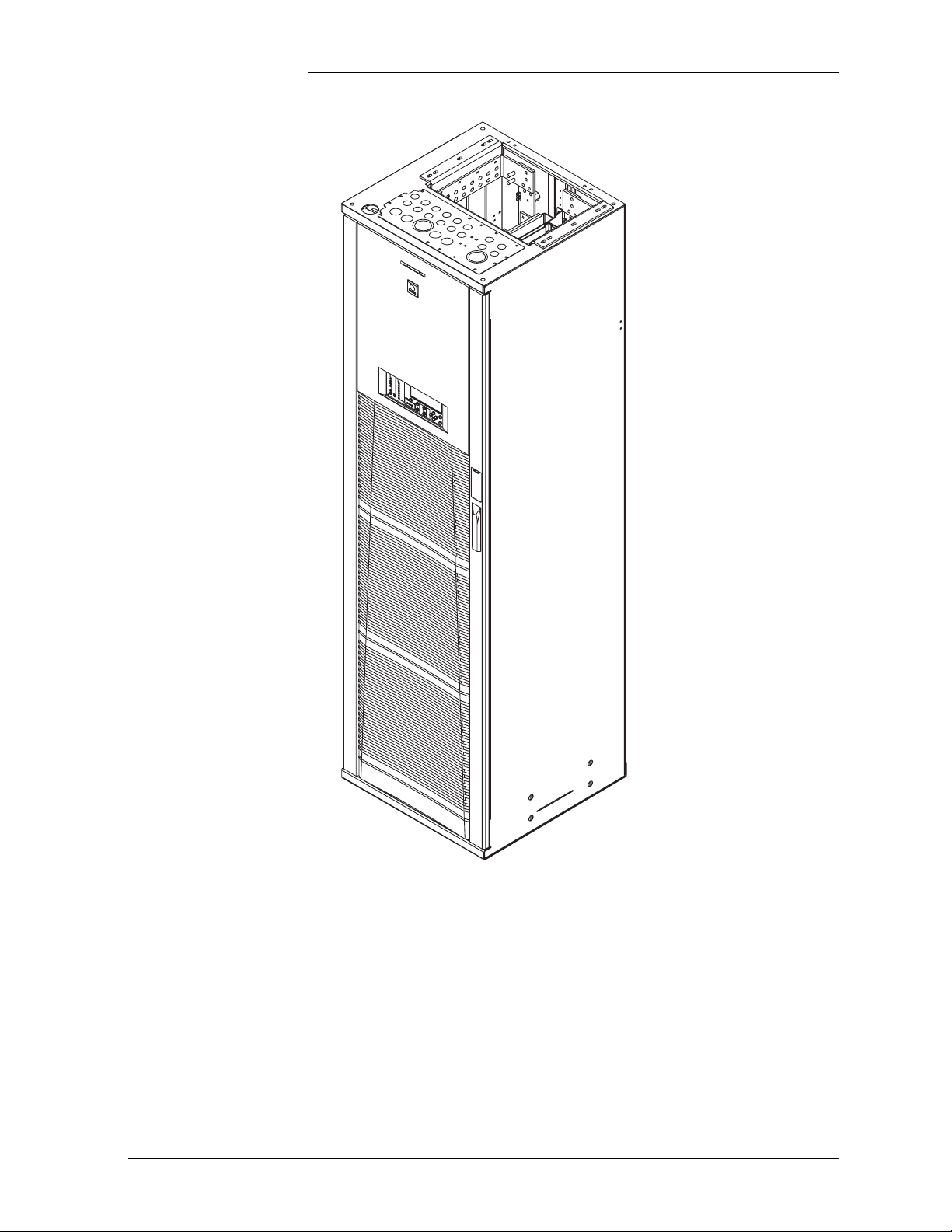
Illustrations Figures 1-1 and 1-2 illustrate the GPS 4812/24 half height and full
height cabinets.
Issue 9 Januray 2008 Introduction 1 - 1
Page 18
Galaxy Power System 4812/24
Figure 1-1: GPS 4812/24 Half Height Initial Cabinet (with Battery Stand)
1 - 2 Introduction Issue 9 Januray 2008
Page 19
Galaxy Power System 4812/24
Figure 1-2: GPS 4812/24 Full Height Initial Cabinet
Issue 9 Januray 2008 Introduction 1 - 3
Page 20

Galaxy Power System 4812/24
Customer Service Contacts
Customer Service, Technical Support, Product Repair and Return, and Warranty Service
For customers in the United States, Canada, Puerto Rico, and the US
Virgin Islands, call 1-800-THE-1PWR (1-800-843-1797). This number
is staffed from 7:00 am to 5:00 pm Central Time (zone 6), Monday
through Friday, on normal business days. At other times this number is
still available, but for emergencies only. Services provided through this
contact include initiating the spare parts procurement process, ordering
documents, product warranty administration, and providing other
product and service information.
For other customers worldwide the 800 number may be accessed after
first dialing the AT&T Direct country code for the country where the
call is originating, or you may contact your local field support center or
your sales representative to discuss your specific needs.
Customer Training Lineage Power offers customer training on many Power Systems
products. For information call 1-972-284-2163. This number is
answered from 8:00 a.m. until 4:30 p.m., Central Time Zone (Zone 6),
Monday through Friday.
Downloads and Software
To download the latest product information, product software and
software upgrades, visit our web site at
http://www.lineagepower.com
1 - 4 Introduction Issue 9 Januray 2008
Page 21
Galaxy Power System 4812/24
2 System Description
Overview
Block Diagram A basic block diagram of the Galaxy Power System 4812/24 is shown
in Figure 2-1. It illustrates the arrangement and interconnections of the
system components from the ac input to the dc output.
AC Input
Rectifiers
AC Input
Power
Chg
Bus
(-)
Return
Bus
(+)
DC Distribution
LVLD
Control
Board
LVL D
Battery Distribution
LVBD
Control
Board
Battery
Shunt
LVB D
To 48 Volt
Loads
DISCHG RTN
48V
Returns
BAT BUS
Battery (-)
CHG RTN
Battery (+)
CO
GND
Sense/Control
Connections
Controller
Figure 2-1: Block Diagram of the GPS 4812/24
Issue 9 Januray 2008 System Description 2 - 1
Page 22

Galaxy Power System 4812/24
Overview, continued
System Components
The power system accepts alternating current from the commercial
utility or a standby ac power source and rectifies it to produce dc power
for the using equipment. The system’s control and alarm functions
interact with the rectifiers and the office. In addition, the system
provides overcurrent protection and charge, discharge, and distribution
facilities. Battery reserve automatically provides a source of dc power if
the commercial or standby ac fails. Battery reserve can be engineered to
supply dc power for a specific period of time. In normal practice, battery
capacity is sized to provide 3 to 8 hours of reserve time.
AC Input connects the commercial and/or standby ac power sources to
the rectifiers within the system and provides overcurrent protection. In
some applications the ac service is wired directly to the rectifiers and
overcurrent protection is provided at the service panel.
Rectifiers convert an ac source voltage into the dc voltage level required
to charge and float the batteries and to power the using equipment.
Controller provides the local and remote control, monitoring, and
diagnostic functions required to administer the power system.
Batteries provide energy storage for an uninterrupted power feed to the
using equipment during loss of ac input or rectifier failure.
DC Distribution Panel provides overcurrent protection, connection
points for the using equipment, and bus bars used to interconnect the
rectifiers, batteries, and dc distribution.
Battery Connection Panel provides connection points for the battery
strings through battery disconnect fuses or contactors and current
monitoring shunts.
2 - 2 System Description Issue 9 Januray 2008
Page 23

Galaxy Power System 4812/24
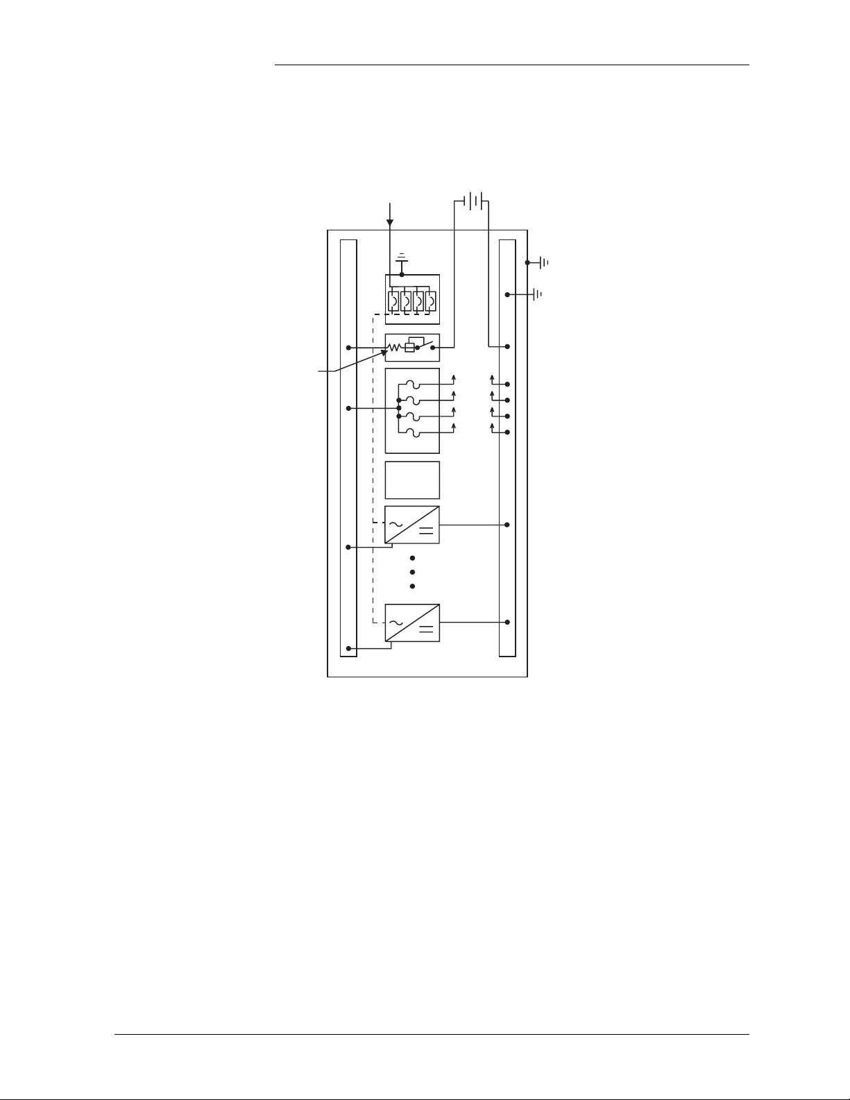
Architecture
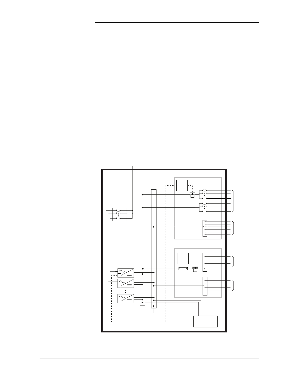
Configurations The GPS 4812/24 is available in two configurations:
• The half height cabinet, shown in Figures 1-1 and 2-2, mounts on
top of a battery stand and can provide up to 800 amperes of dc
power.
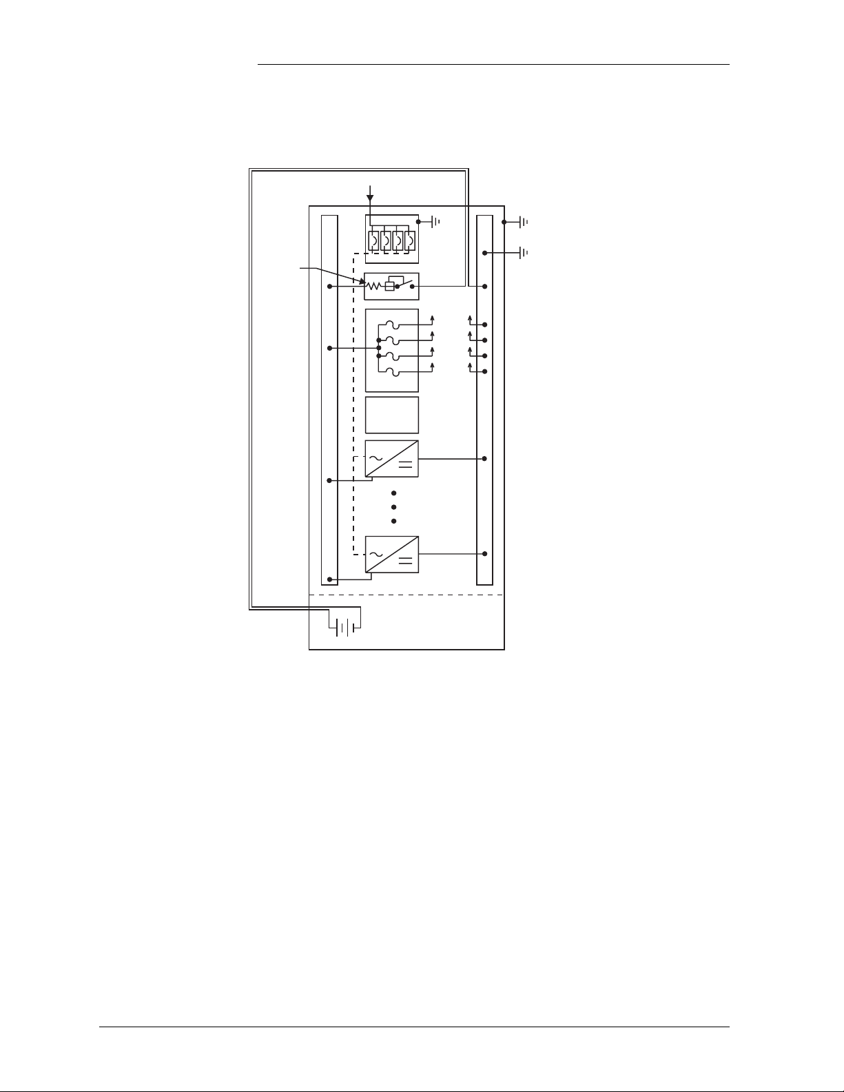
• The full height (7-foot) cabinet, shown in Figures 1-2 and 2-3, can
provide up to 1,600 amperes of dc power.
Each cabinet contains ac distribution, dc distribution panels, a battery
connection panel, rectifiers, termination points for load circuits, and a
system controller.
Illustrations Figure 2-4 shows how supplemental full-height cabinets may be added
to grow the system to 7,040 amperes. The rectifier output buses are
interconnected to permit the cabinet to share current and ensure
common voltage references for all system rectifiers.
Figures 2-5 and 2-6 show open-door views of the half height and full
height cabinets.
Issue 9 Januray 2008 System Description 2 - 3
Page 24
Galaxy Power System 4812/24
AC
Battery
Shunt
Control
and
Monitor
Cabinet
Ground
AC
Ground
System (CO)
Ground
To Loads
Battery String(s)
Mounted Below
Half Height Cabinet
Figure 2-2: Schematic of Half Height Cabinet
2 - 4 System Description Issue 9 Januray 2008
Page 25
Galaxy Power System 4812/24
AC
AC
Ground
Battery
String
Cabinet
Ground
System (CO)
Ground
Battery
Shunt
Control
and
Monitor
To Loads
Figure 2-3: Schematic of Full Height Cabinet
Issue 9 Januray 2008 System Description 2 - 5
Page 26
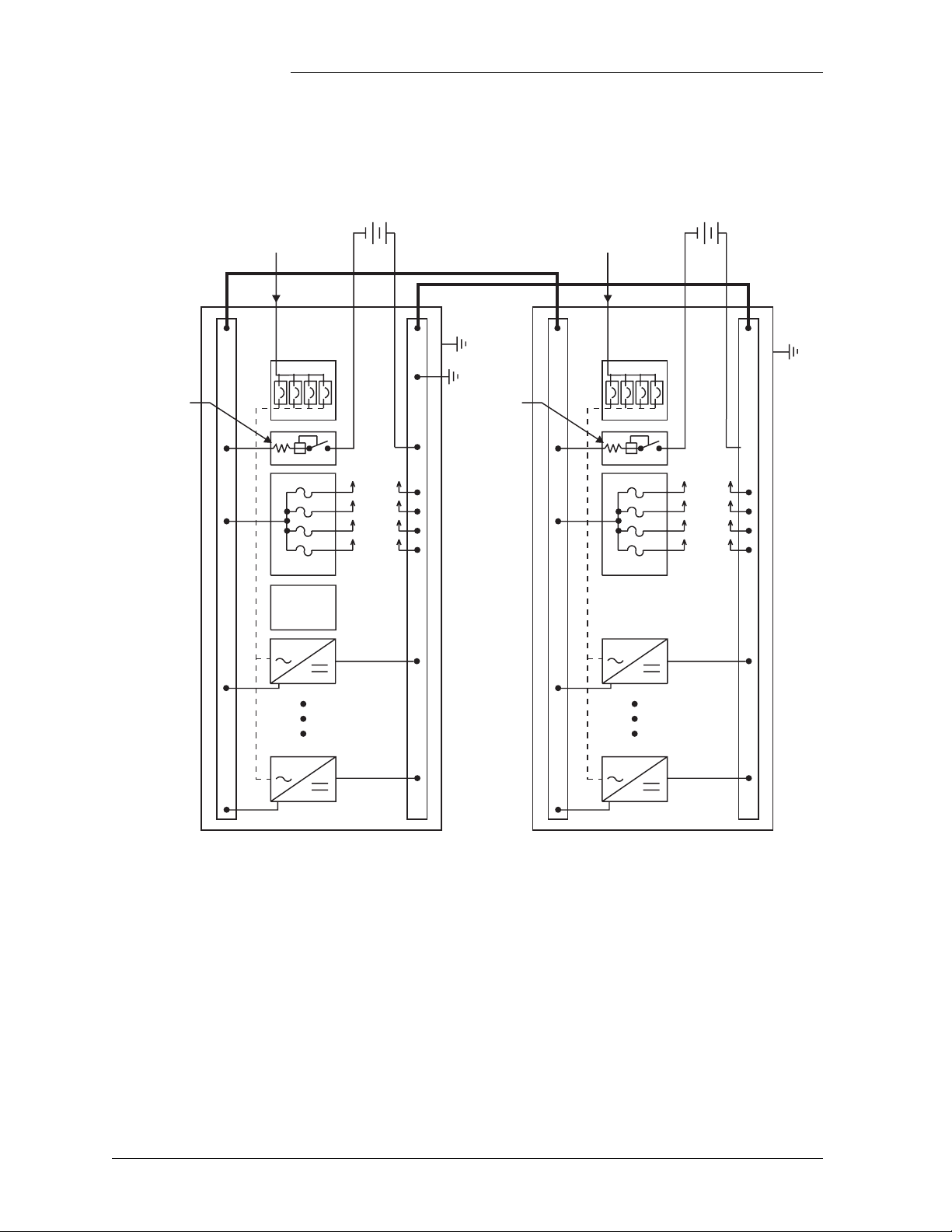
Galaxy Power System 4812/24
Battery
Shunt
AC
Input
Monitor
Control
and
Battery
String
Battery
String
AC
Input
Battery
Shunt
To LoadsTo Loads
Initial Cabinet Supplemental Cabinet
Figure 2-4: Schematic of Two-cabinet System Architecture
2 - 6 System Description Issue 9 Januray 2008
Page 27
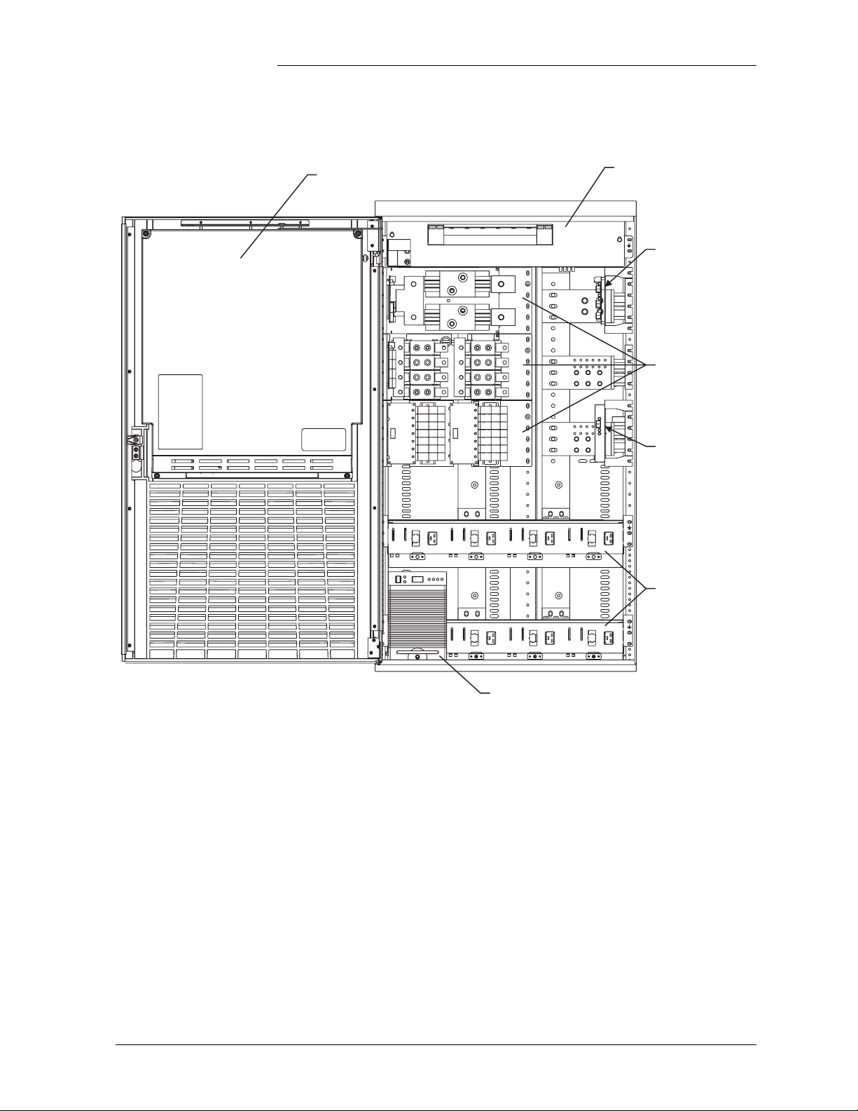
Galaxy Power System 4812/24
Controller Access Panel
AC Panel
(Circuit Breakers)
LVBD
Control
Circuit
Miscellaneous
DC Distribution
Panels
LVLD
Control
Circuit
596 Rectifier
Figure 2-5: Half Height GPS 4812/24 with Door Open
Rectifier
Shelves
Issue 9 Januray 2008 System Description 2 - 7
Page 28
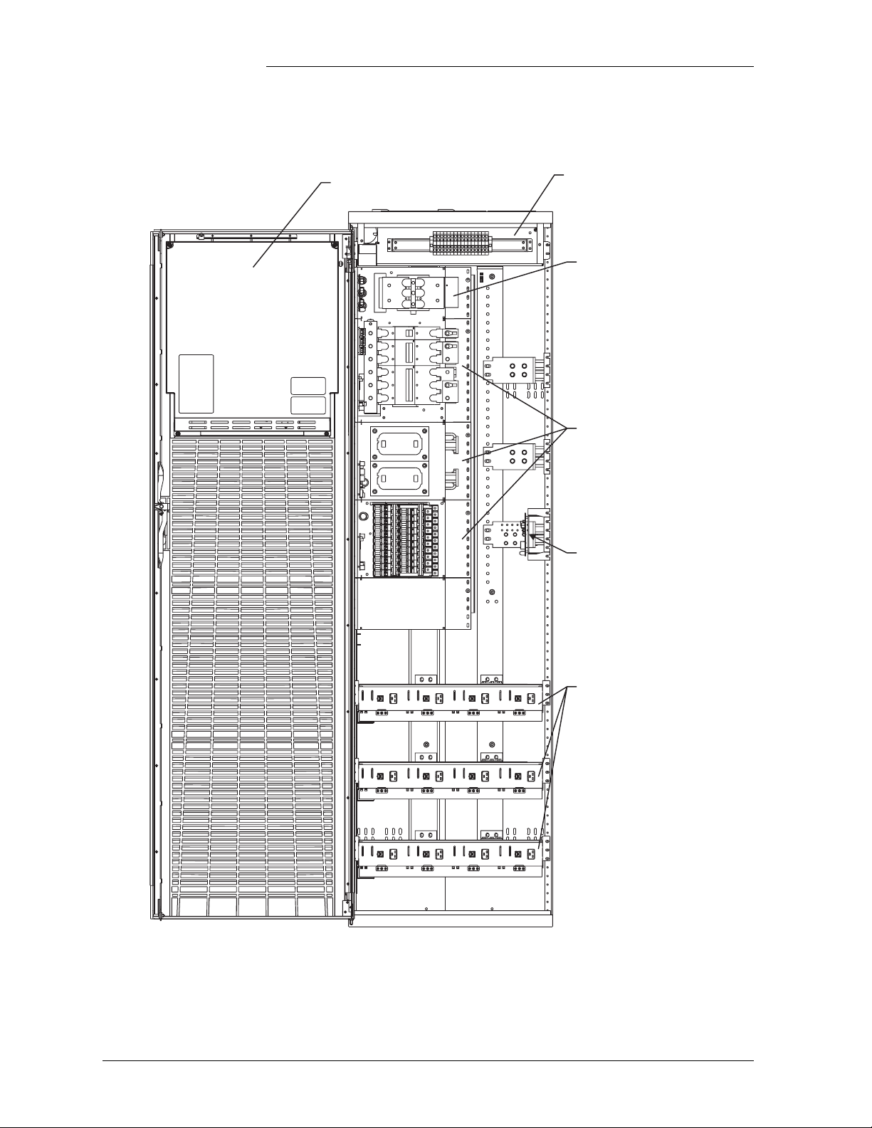
Galaxy Power System 4812/24
Controller Access Panel
AC Panel
(Terminal Strip)
Low Voltage Battery
Disconnect Panel
Miscellaneous
DC Distribution
Panels
LVLD
Control
Circuit
Rectifier
Shelves
Figure 2-6: Full Height GPS 4812/24 with Door Open
2 - 8 System Description Issue 9 Januray 2008
Page 29

Galaxy Power System 4812/24
3 Galaxy Controllers
Overview
Introduction The GPS 4812/24 is available with either the Galaxy Millennium
Controller or the Galaxy Vector Controller.
This section describes the operation of each controller. It also provides
detailed information about the features of their front panel keys, LEDs,
and displays.
Note If your cabinet has a metal door and a Galaxy Millennium Controller,
some components of the controller will look different than in this
manual, but operation is the same.
If your cabinet has a metal door and a Galaxy Vector Controller, your
controller differs substantially from the version shown in this manual.
Refer to Issue 6 of this manual for information pertaining to your
controller.
Issue 9 Januray 2008 Galaxy Controllers 3 - 1
Page 30
Galaxy Power System 4812/24
Galaxy Millennium Controller
Design The Galaxy Millennium Controller is equipped with a Basic control
board (BSH) for basic operations and an optional Intelligent control
board (BSJ) that provides advanced local and remote monitoring and
data acquisition features. These CPU control boards monitor each
other’s status and issue appropriate alarms in the event a failure occurs.
Each cabinet used with the Galaxy Millennium Controller requires a bay
interface card (BIC). The BIC acts as an interface to the cabinet control
and alarm signals.
User Interface and Display
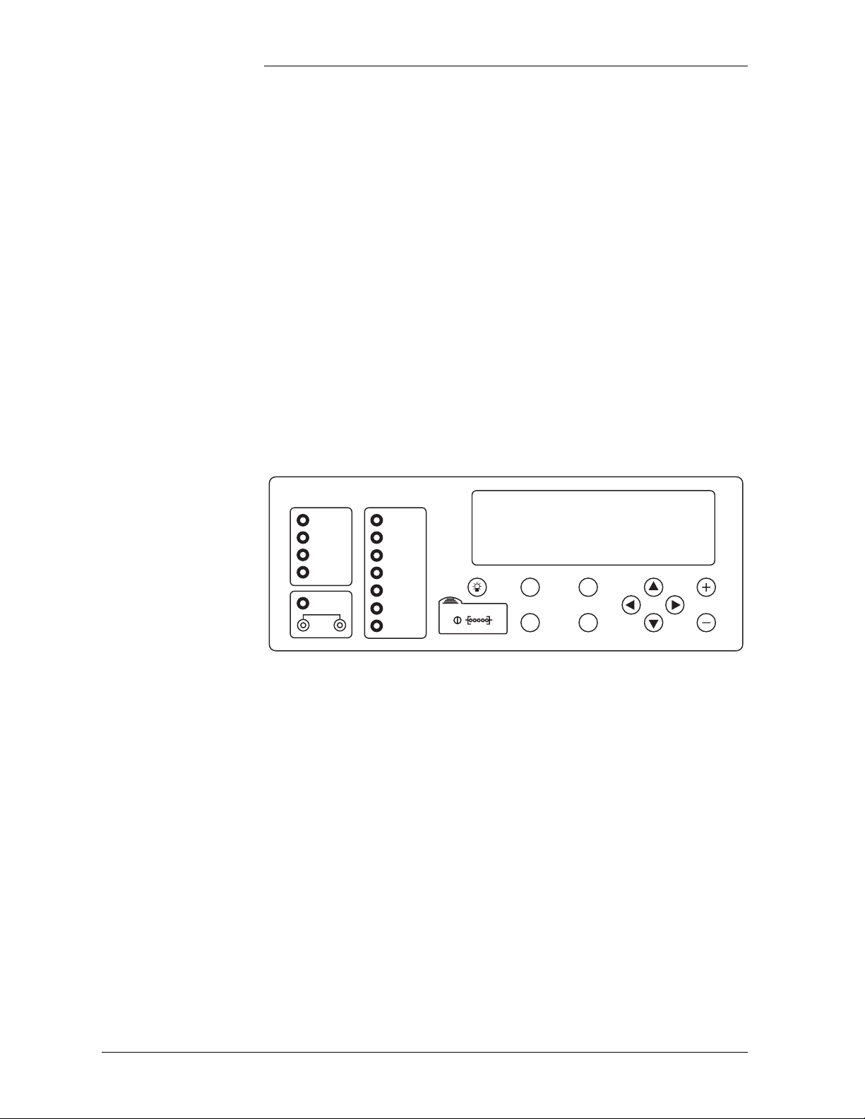
The Millennium’s primary user interface is a panel that includes a
backlit LCD front panel display that can be viewed in English or
Spanish, two rows of LEDs, an array of pushbutton keys, and a pair of
test jacks. Figure 3-1 illustrates the Millennium’s front panel.
Galaxy Millennium Controller
Alarm Status
Critical
Major
Minor
Normal
Battery on
Discharge
V
Equipment Status
AC System
Battery
Controller
Distribution
Rectifier
Remote
Modules
Modem
Escape Help
Menu Enter
Figure 3-1: Galaxy Millennium Controller Front Panel
Default Display The default display shows basic system status. The controller returns to
this display approximately three minutes after the last time a key is
pressed. The information on the screen is updated automatically
approximately every two seconds.
The default screen display is similar to the following: The first line
shows the number of alarms (0) and warnings (0) present in the system,
the date, and the time. The next two lines show the system voltage and
the system load. The last line shows the system mode, which can be one
of the following:
•FLOAT
•BOOST
• STC (Slope Thermal Compensation)
• BATT TEST
3 - 2 Galaxy Controllers Issue 9 Januray 2008
Page 31

Galaxy Power System 4812/24
Galaxy Millennium Controller, continued
LEDs Two rows of LEDs show the source and severity of various alarms. An
alarm lights one status LED and one or more alarm LEDs. If more than
one alarm LED lights, the status LED that lights will indicate the most
severe active alarm.
• The first row includes four LEDs, labeled Alarm Status. They
indicate the severity of the reported alarm:
Critical
Major
Minor
Normal
The Battery on Discharge LED is also in this row.
• The second row has seven LEDs, labeled Equipment Status. They
indicate the source of the alarm:
AC System
Battery
Controller
Distribution
Rectifier
Remote Modules
The Modem LED illuminates when the internal modem is in use.
Test Jacks A pair of test jacks allows direct measurement of the dc bus sense
voltage being monitored by the controller.
Issue 9 Januray 2008 Galaxy Controllers 3 - 3
Page 32

Galaxy Power System 4812/24
Galaxy Millennium Controller, continued
Pushbutton Keys A group of pushbutton keys below the backlit LCD display provides the
primary user interface with the controller. These keys are used singly or
in combination to navigate through the controller’s menus.
The following is a general description of the pushbutton keys:
• ESCAPE: Return to the immediate higher level menu.
• HELP: Displays limited on-line help information.
• MENU: View the MAIN menu.
• ENTER: Select a menu item.
• Up arrow: Moves the cursor up one line.
• Down arrow: Moves the cursor down one line.
• Left arrow: Moves the cursor left one field.
• Right arrow: Moves the cursor right one field.
• + and -: Increase or decrease parameter values.
• Lamp test: Tests the controller’s circuit board LEDs and front panel
LEDs. It will also test the indicators of serially connected rectifiers.
Access Panel A rubber flap can be opened to access the local port connector and the
display brightness potentiometer. The DB-9 local port connector
supports standard RS232 serial communication. Refer to the Galaxy
Millennium Controller product manual for additional details concerning
port configuration and isolation.
3 - 4 Galaxy Controllers Issue 9 Januray 2008
Page 33

Galaxy Power System 4812/24
Galaxy Vector Controller
Design The Galaxy Vector Controller consists of an electronics board and a
terminal connection board. The Vector provides a wide range of control
and monitoring features and issues appropriate alarms in the event a
failure occurs.
User Interface and Display
The Vector’s primary user interface is a panel that includes an LCD
display, three LEDs, and an array of pushbutton keys. Figure 3-2
illustrates the Vector’s front panel.
Galaxy Vector Controller
OK
Figure 3-2: Galaxy Vector Controller Front Panel
Default Display The default display shows the system voltage, load current, and plant
state. When active alarms are present, the last line of the display will
read “← View Alarms.” Press the corresponding button to view the
active alarms.
LEDs LEDs indicate the alarm state of the system.
Issue 9 Januray 2008 Galaxy Controllers 3 - 5
Page 34

Galaxy Power System 4812/24
Galaxy Vector Controller, continued
Pushbutton Keys Pushbutton keys around the backlit LCD display provide the primary
user interface with the controller. These keys are used singly or in
combination to navigate through the controller’s menus.
The four keys to the left of the LCD display are soft keys. When a soft
key is active, its label begins with ← and is displayed on the
corresponding line to the right of the key.
• This key is the Home key
– If viewing the default screen, Home sends you to the main
menu.
– If viewing the main menu, Home returns you to the default
screen.
– If viewing a menu screen other than the main menu, Home
returns you to the main menu.
– If viewing alarms, Home returns you to the default screen.
• Up arrow: Scrolls up or increments a value.
• Down arrow: Scrolls down or decrements a value.
• Left arrow: Moves the cursor left one character when editing a
value.
• Right arrow: Moves the cursor right one character when editing a
value.
Access Panel A rubber flap can be opened to access the local port connector and the
display brightness potentiometer. The DB-9 local port connector
supports standard RS232 serial communication. Refer to the Galaxy
Vector Controller product manual for additional details concerning port
configuration and isolation.
3 - 6 Galaxy Controllers Issue 9 Januray 2008
Page 35

Galaxy Power System 4812/24
Reference Material
Controller Product Manuals
RPM System Product Manual
Either a Galaxy Millennium Controller product manual (Select Code
167-792-180) or Galaxy Vector Controller product manual (Select Code
167-792-112) is furnished with every GPS 4812/24. Refer to this
manual for information regarding configuration and operation.
Refer to the Galaxy Remote Peripheral Monitoring System product
manual (Select Code 167-790-063) for additional information regarding
module operation.
Issue 9 Januray 2008 Galaxy Controllers 3 - 7
Page 36

Page 37

Galaxy Power System 4812/24
4 Rectifiers
596 Series A and D
Overview The 596 Series A rectifier (55A) and 596D rectifier (110A) operate from
single-phase ac service with a phase-to-phase voltage within the range
of 176-264Vac.
The rectifiers are shipped separately from the cabinets for quick and
straightforward installation into rectifier shelves at the site.
Interconnections to ac input, dc output, and control signals occur
automatically during insertion. The rectifier is keyed to prevent
installation of the wrong rectifier. No settings or adjustments to
potentiometers are necessary. The installer must set the rectifier’s ID
using the ON/STBY switch to allow the controller to learn the rectifier’s
physical location.
The 596A and D rectifiers are UL Recognized for both the U. S. and
Canada, comply with UL1950 (Information Technology Equipment),
and meet EN60950 requirements.
Front Panel Display
Power Switch This three-position switch has two active states:
• It controls the on/standby state of the rectifier.
• It is used to set the rectifier ID.
Status Indicators In addition to the ON and STBY LEDs, four other LEDs on the
rectifier’s faceplate indicate the rectifier’s condition.
• The ALM LED is red and lights whenever the rectifier fails.
Issue 9 Januray 2008 Rectifiers 4 - 1
Page 38

Galaxy Power System 4812/24
Front Panel Display, continued
• The LIM LED is yellow and lights when the unit is in current limit.
• The FAN AL M LED is red and lights when the fan inside the
rectifier is not functioning properly.
• The BST LED is yellow and lights when the rectifier is in boost
mode.
Current Display This display indicates the current of the rectifier. Upon specific
no-power conditions, the 3-digit display will show informative
messages.
Lamp Test To test the LEDs on the rectifier front panel, press the Lamp Test button
on the controller.
ID
ON
STBY
ALM
LIM FAN
ALM
BST
Figure 4-1: Rectifier Front Panel
4 - 2 Rectifiers Issue 9 Januray 2008
Page 39

Features
Galaxy Power System 4812/24
Output Current “Walk-in”
Output Protection Rectifier is equipped with an internal fuse for plant protection if a fault
Electronic Current Limit
High Voltage Shutdown (HVSD)
Restart Upon shutdown, the rectifier will attempt to restart. The rectifier will
This circuit controls the time (up to eight seconds) required for the
rectifier to reach normal operating conditions after it is turned on. This
feature minimizes the starting surge on the customer's power source.
occurs in a rectifier.
When the output current tends to increase above the current limit set
point, the current limit circuit overrides the voltage regulating signal and
safely limits the output current of the rectifier, thus preventing damage
to itself or the load.
The rectifier senses the voltage at its output terminals. If this voltage is
too high, the rectifier will shut down to prevent the high voltage from
damaging itself or the load.
also accept a restart command from the controller for a remote restart.
The rectifier will attempt to restart three times before issuing a rectifier
fail alarm to the controller.
Fan Alarm and Control
Thermal Alarm The rectifier senses the internal operating temperature and will issue a
Autonomous Operation
Controller Communications Alarm
The rectifier contains a cooling fan. The fan’s speed, which is based on
ambient temperature and output power level, is lowered during low-load
and low-temperature conditions to minimize audible noise and
maximize fan life.
thermal alarm if the internal temperature exceeds a safe operating level.
Ambient temperatures above the maximum rating will result in a
rectifier shutdown and the issuing of a thermal alarm (TA).
Rectifiers will continue to power the load if the controller fails or if
communication is lost.
When communications between the rectifier and controller are
interrupted, the rectifier continues to operate and the red ALM LED on
the rectifier blinks.
Issue 9 Januray 2008 Rectifiers 4 - 3
Page 40

Galaxy Power System 4812/24
Features, continued
Connectorized The rectifiers provide the controller with a full complement of status and
alarm signals. The rectifier status and alarm signals, ac input, and dc
output are all connectorized for easy installation and maintenance.
System connections are made when the rectifier is plugged into the
shelf. No additional connections are required.
“Forced” Load Sharing
Internal rectifier circuitry will allow multiple rectifiers to share load in
the event communication to the controller is lost or the controller
malfunctions.
4 - 4 Rectifiers Issue 9 Januray 2008
Page 41

Galaxy Power System 4812/24
5 AC Input Panels
Overview
AC Service The ac input panel provides the facility to terminate 3-phase ac service
to the GPS 4812/24 system or to distribute individual 1-phase ac
supplies to each of the system rectifier positions. Depending upon the
option ordered, the panel will connect 3-wire (three phases), 4-wire
(three phases + neutral), or individual 2-wire (single phase, either 2 hot
leads or 1 hot lead and neutral) input ac service.
Some systems provide circuit breakers to protect the conductors
providing ac service to the individual rectifiers. Other systems contain a
terminal strip and the conductors are protected by circuit breakers
located in the building’s ac service panel.
Note: All wire sizes were based on the US National Electric Code.
Illustrations Circuit breaker panels are shown in Figures 5-1, and Figure 5-2 shows
terminal strip panels.
Issue 9 Januray 2008 AC Input Panels 5 - 1
Page 42

Galaxy Power System 4812/24
ED83142-30 G7, G19
H569-436 G72F, G172F
ED83142-30 G6, G6M, G23
H569-436 G71H, G73F, G74F, G74H, G173F
ED83142-30 G21
H569-436 G171H
Figure 5-1: AC Input Circuit Breaker Panels
5 - 2 AC Input Panels Issue 9 Januray 2008
Page 43

Galaxy Power System 4812/24
ED83142-30 G9, G20
H569-436 G77F, G78F, G177F, G178F
ED83142-30 G8, G22
H569-436 G76H, G79F, G176H, G179F
ED83142-30 G22
H569-436 G175H
Figure 5-1: AC Input Terminal Strip Panels
Issue 9 Januray 2008 AC Input Panels 5 - 3
Page 44

Page 45

Galaxy Power System 4812/24
6 Battery Connection Panels
Overview
Function Batteries are connected to the GPS 4812/24 cabinets on battery
connection panels located in the cabinet directly below or behind the ac
input panel. All panels include the battery shunts and an alarm card that
communicates with the controller to provide battery current and status
information. As options, the panels may include fuses or low voltage
battery disconnect/reconnect (LVBD/R) contactors. When equipped
with contactors, a contactor control card provides local/manual control
of the contactors.
Note: If no battery panel is needed (for full height supplemental cabinets
only), H569-436 G33F is selected as a placeholder in the order.
Illustrations The battery connection panels are shown in Figures 6-1 through 6-10.
Note: Battery connection panels are blue; dc distribution panels are
white.
Issue 9 Januray 2008 Battery Connection Panels 6 - 1
Page 46

s
Galaxy Power System 4812/24
Two 1000A Shunts
Two 500A Contactors
Contactor Control Cards
Connects to
Charge Return Bus
9" REF
(229mm)
1200A Contactor
Figure 6-1: H569-436 G30 (ED83143-31 G32)
Battery Connection Panel
1500A Shunt
Connects to
Charge Return Bu
6" REF
(152mm)
Contactor Control Card
Figure 6-2: H569-436 G31 (ED83143-31 G31)
Battery Connection Panel
6 - 2 Battery Connection Panels Issue 9 Januray 2008
Page 47

Galaxy Power System 4812/24
Terminal Card
Alarm Card
(2) NH3 Fuse Holders
Two 600A Shunts
Connects to
Charge Return Bus
9" REF
(229mm)
Figure 6-3: H569-436 G34 (ED83143-31 G41)
Battery Connection Panel
Alarm/Terminal
Card
(1) NH3 Fuse Holder
600A Shunt
Connects to
Charge Return Bus
6" REF
(152mm)
Figure 6-4: H569-435 G35 (ED83143-31 G42)
Battery Connection Panel
Issue 9 Januray 2008 Battery Connection Panels 6 - 3
Page 48
600A Shunt
Galaxy Power System 4812/24
800A Contactor
Contactor Control Card
Figure 6-5: H569-436 G36H (ED83143-31 G33)
Battery Connection Panel
Alarm/Terminal Card
(3) 600A Fuses
(1) 1200A Contactor
(G60 only)
15" REF
(381mm)
(3) 1000A Shunts
Connects to
Charge Return Bus
Note: For more information, refer
to the OLE Product Manual,
Select Code 167-792-200
Figure 6-6: H569-436 G37F/38F (ED83143-31 G60/61)
Battery (OLE) Connection Panel
6 - 4 Battery Connection Panels Issue 9 Januray 2008
Page 49

Galaxy Power System 4812/24
Alarm
Cards
H569-436
G80
G81
G82
Contactor Control Card
Includes:
1 G31
1 G43
1 G31
2 G43
1 G31
3 G43 (shown)
1200A Contactor
24" REF
(610mm)
ED83143-31 G31
1200A Contactor
ED83143-31 G43
Two NH3 DIN Fuses
Two 600A Shunts
Connect to
Charge Return Bus
Connect to
Charge Return Bus
Figure 6-7: H569-436 G80/81/82 (ED83143-31 G31/43)
Battery Connection Panel
Issue 9 Januray 2008 Battery Connection Panels 6 - 5
Page 50

Galaxy Power System 4812/24
600A Shunt
Figure 6-8: H569-436 G84H (ED83143-31 G34)
Battery Connection Panel
1000A Shunt
Figure 6-9: H569-436 G85F (ED83143-31 G35)
Battery Connection Panel
6 - 6 Battery Connection Panels Issue 9 Januray 2008
Page 51

Galaxy Power System 4812/24
Terminal Card
800A Contactor
12" REF
(152mm)
Connects to
Charge Return Bus
Alarm Card
Shunts (Provided
with circuit breakers)
6 Circuit Breaker Positions
(Circuit breakers ordered separately)
Figure 6-10: H569-436 G86/87 (ED83143-31 G63/64)
Battery Connection Panel
Issue 9 Januray 2008 Battery Connection Panels 6 - 7
Page 52

Page 53

Galaxy Power System 4812/24
7 DC Distribution Panels
Overview
Function A variety of dc distribution panels is available for the GPS 4812/24
system, including DIN standard fuse holders and circuit breakers and
U. S. standard fuse holders and circuit breakers. All panels are equipped
with an alarm card. When a fuse operates or a circuit breaker trips, a red
LED on the alarm card lights, the cabinet alarm lights, and the alarm is
transmitted to the controller. Most panels are also available with
contactors to provide low voltage load disconnect.
Illustrations The dc distribution panels are illustrated in Figures 7-1 through 7-11.
Note: DC distribution panels are white; battery connection panels are
blue.
Issue 9 Januray 2008 DC Distribution Panels 7 - 1
Page 54

Galaxy Power System 4812/24
Alarm/Terminal Card
14 Positions for U.S. Plug-in
Circuit Breakers or Fuse Holders
Connects to
Charge Return Bus
6" REF
(152mm)
Clear Lexan
Covers
Figure 7-1: H569-436 G40/50 (ED83143-31 G11)
DC Distribution Panel
Alarm/Terminal Card
22 Positions for U.S. Plug-in
Circuit Breakers or Fuse Holders
Connects to
Charge Return Bus
9" REF
(229mm)
Clear Lexan Covers
Figure 7-2: H569-436 G41/51 (ED83143-31 G12)
DC Distribution Panel
7 - 2 DC Distribution Panels Issue 9 Januray 2008
Page 55

Galaxy Power System 4812/24
Alarm/Terminal Card
3 Positions for Large
U.S. Circuit Breakers
with Shunts
Connects to
Charge Return Bus
6" REF
(152mm)
Figure 7-3: H569-436 G42 (ED83143-31 G2)
DC Distribution Panel
Terminal Card
6 Positions for Large
U.S. Circuit Breakers
with Shunts
Connects to
Charge Return Bus
12" REF
(305mm)
Alarm Card
Figure 7-4: H569-436 G43 (ED83143-31 G1)
DC Distribution Panel
Issue 9 Januray 2008 DC Distribution Panels 7 - 3
Page 56

Galaxy Power System 4812/24
Terminal Card
5 Positions for Large
U.S. Circuit Breakers
with Shunts
Alarm Card
Connects to
Charge Return Bus
9" REF
(229mm)
Figure 7-5: H569-436 G44 (ED83143-31 G5)
DC Distribution Panel
Alarm/Terminal Card
10 Positions for Plug-in
(Bullet Style) Circuit Breakers
Connects to
Charge Return Bus
6" REF
(152mm)
Figure 7-6: H569-436 G46 (ED83143-31 G15)
DC Distribution Panel
7 - 4 DC Distribution Panels Issue 9 Januray 2008
Page 57

Galaxy Power System 4812/24
Alarm/Terminal Card
10 Medium U.S.
Fuse Holders
Connects to
Charge Return Bus
6" REF
(152mm)
Figure 7-7: H569-436 G52 (ED83143-31 G53)
DC Distribution Panel
2 600A Shunts
2 U.S. Large
Fuse Holders
9" REF
(229mm)
Alarm/Terminal Card
Connects to
Charge Return Bus
Figure 7-8: H569-436 G53 (ED83143-31 G55)
DC Distribution Panel
Issue 9 Januray 2008 DC Distribution Panels 7 - 5
Page 58

Galaxy Power System 4812/24
14 Positions for DIN Circuit Breakers (1-63A)
or DIN Fuse Holders (10 x 38mm fuses, 1-32A)
10 Positions for DIN Circuit Breakers (80-125A)
Alarm Cards
or DIN Fuse Holders (14 x 51mm fuses, 1-50A)
or
Connects to
Charge Return Bus
6" REF
(152mm)
Figure 7-9: H569-436 G60/61/65/66 (ED83143-31 G71)
DC Distribution Panel
Alarm/Terminal Card
8 NH00 Fuse Holders
Connects to
Charge Return Bus
6" REF
(152mm)
Figure 7-10: H569-436 G67 (ED83143-31 G22)
DC Distribution Panel
7 - 6 DC Distribution Panels Issue 9 Januray 2008
Page 59

Galaxy Power System 4812/24
Alarm/Terminal Card
2 NH2 Fuse Holders
Connects to
Charge Return Bus
6" REF
(152mm)
Figure 7-11: H569-436 G68 (ED83143-31 G21)
DC Distribution Panel
Issue 9 Januray 2008 DC Distribution Panels 7 - 7
Page 60

Page 61

Galaxy Power System 4812/24
8 Circuit Boards
Overview
Function Circuit boards (sometimes referred to as “cards”) are included in the
battery connection and dc distribution panels to provide data required by
the controller.
Terminal Boards Terminal boards are used to provide shunt voltage data to the controller,
where it is used to calculate current. Terminal boards located on the
battery connection panels provide data that is used to calculate battery
current; data from terminal boards located on the dc distribution panels
is used to calculate load current.
Alarm Boards Alarm boards perform two functions:
• monitor panel functions and activate local indicators when faults
occur on the panel
• provide alarm data to the controller
Alarm/Terminal Boards
BLJ Terminal Board
Alarm/terminal boards combine the functions of alarm boards and
terminal boards.
The BLJ terminal board is located inside the cabinet door. The BLJ is
the termination point for all signal cables in each cabinet and between
cabinets.
Issue 9 Januray 2008 Circuit Boards 8 - 1
Page 62

Galaxy Power System 4812/24
Overview, continued
Contactor Control Board
Millennium Systems
Vector Systems The initial cabinet contains the Vector controller, which consists of a
Contactor control boards provide four functions:
• Monitor and report shunt voltage to the controller
• Monitor and report contactor status to the controller
• Operate the contactor based on controller commands
• Operate or block the contactor based on maintenance switch
settings
Each initial and supplemental cabinet in a Millennium system has a Bay
Interface Card (BIC) that attaches to the cabinet’s terminal board (BLJ).
The BIC provides controller access to alarm monitoring, battery
voltages, battery currents, and temperature probes in the cabinet through
the serial rectifier bus. See Figure 12-3.
GCM3 control board mounted on the BLJ terminal connection board.
Supplemental cabinets do not require a GCM3 control board or BIC. See
Figure 12-5.
8 - 2 Circuit Boards Issue 9 Januray 2008
Page 63

Galaxy Power System 4812/24
9 Specifications
GPS 4812/24
Table 9-A: Galaxy Power System 4812/24 Specifications
Electrical
AC Input
Input Distribution
592A2
• 125A circuit breaker per 2-shelf cabinet
• 150A circuit breaker per 3-shelf cabinet
• 25A circuit breaker per rectifier for individual feeds
596D
Minimum Wire Size
596A2
596D
Output Current
596A2
596D
Output Current
596A2
596D
1. With Galaxy Millennium Controller
55 - 1,200A
110 - 3,200A
• 110 / 125A circuit breaker per 1-shelf cabinet
• 2 x 110 / 125A circuit breaker per 2-shelf cabinet
• 2 x 150A circuit breaker per 3-shelf cabinet
• 50A circuit breaker per rectifier for individual feeds
• 2 gauge/35 mm2 - 1 and 2-shelf cabinet
• 1/0 gauge/50 mm2 - 3-shelf cabinet
• 10 gauge/6 mm2 - per rectifier for individual feeds
• 2 gauge/35 mm2 - 1-shelf cabinet
• 2 x 2 gauge/35 mm2 - 2-shelf cabinet
• 2 x 1/0 gauge/50 mm2 - 3-shelf cabinet
• 8 gauge/10 mm2 - per rectifier for individual feeds
Cabinet Output -48V
Full Height Half Height
55 - 800A
110 - 1,600A
System Output -48V
2 x Full Height 1 Half Height + 1 Full Height Maximum System
55 - 1,200A
110 - 2,400A
50 - 400A
110 - 800A
3,520A
7,040A
1
1
Issue 9 Preliminary Januray 2008 Specifications 9 - 1
Page 64

Galaxy Power System 4812/24
Table 9-A: Galaxy Power System 4812/24 Specifications (continued)
Mechanical
Cabinet
Full Height Half Height
Nominal Cabinet Dimensions
(H x W x D)
Rectifiers 1 - 12 or 1 - 16 1 - 8
Controller 1
Battery Disconnect Modules 0 - 1
DC Distribution 1 - 6 1 - 3
Rectifiers 1 - 12 or 1 - 8 N/A
Battery Disconnect Modules 0 - 1 N/A
DC Distribution 1 - 6 N/A
Operating Ambient Temperature
596A2
596D
Altitude -50 to 4000 meters
Humidity 5% to 90% non-condensing
Radiated and Conducted
Emissions
Electromagnetic Immunity Level B
Earthquake Rating Zone 4, upper floors
Agency Approvals CE Marked, UL
2100 H x 600 W x 500 D mm
(82.6 H x 23.6 W x 19.7 in.)
Units Per Initial Cabinet
Full Height Half Height
Units Per Supplemental Cabinet
Environmental
-40°C to +85°C
-40°C to +75°C
Note: For altitudes between 1500 and 4000 meters, derate the maximum
temperature by 0.656°C per 100 meters.
EN50082-1, EN50082-2, EN50081, EN61000
Stand ards Co mpliance
Underwriters Laboratories (UL) Listed per Subject Letter 1801, DC Power
Distribution Centers for Telecommunications Equipment
1080 H x 600 W x 500 D mm
(42.5 H x 23.6 W x 19.7 D in)
9 - 2 Specifications Issue 9 Preoiminary Januray 2008
Page 65

Galaxy Power System 4812/24
Rectifier
Table 9-B: Rectifier Specifications
Electrical
Input
Voltage Range 176-264Vac, 2-wire, single phase
Frequency Range 47 - 63 Hz
Power Factor > 0.98 for loads > 50%
AC Surge Protection: It is important that ac surges reaching rectifiers do not exceed the capacity of the
rectifier internal surge protection. Protection must be provided external to the GPS system, if necessary, to
limit surge energy reaching the rectifiers. Site surge protection must be coordinated with rectifier internal
surge protection and must clamp at a lower voltage than the rectifier internal protection. The internal
protection voltage and current characteristics of the rectifiers are as follows:
Phase to Phase Voltage MOV Conduction Current
320Vac (RMS) 0A
620V maximum clamping 1mA (DC test current)
810Vpeak 100A peak (8 x 20μs)
Output All
High Voltage Shutdown
Internal Selective High Voltage Shutdown
(ISHVSD)
Float: 56.0Vdc Nom.1,
Boost: 56.0Vdc Nom.1,
Equalize: 59.52 ± 1Vdc Nom.1,
2
2
2
Backup High Voltage Shutdown
(BUHVSD)
1. Selectable/programmable through Galaxy Controller
2. Factory default settings – actual range is 44 - 60Vdc
3. Factory default settings – Float/Boost range is 58.51 - 60.53Vdc,
Equalize range is 65.2 - 67.0Vdc
Float/Boost:59.52Vdc
Equalize: 66.0Vdc3
3
Output 596A2
Output Power
Output Current
1
1
3,000W maximum
55Adc maximum from -40°C to +65°C
42.5Adc at +75°C
30Adc at +85°C
Rectifier self-derates at approximately
1 ampere per degree C (+65°C to +85°C)
Float/Boost Voltage 44-58Vdc
Total Harmonic Distortion <5% at Nominal Vac and >25Adc
Regulation ±0.5%
Ripple 100 mVrms
Noise < 2mV psophometric
Current Limit Set Point 15A-55A
Note: When using the maximum 16 rectifiers in a
cabinet, do not exceed 50 amperes current limit per
rectifier at 65°C.
1. See Figure 9-1: Output Current vs. Temperature.
Issue 9 Preliminary Januray 2008 Specifications 9 - 3
Page 66

Galaxy Power System 4812/24
Table 9-B: Rectifier Specifications (Continued)
Output 596D
Output Power
Output Current
1, 2
1, 2
Float/Boost Voltage 42-58Vdc
Total Harmonic Distortion <5% at Nominal Vac and >50Adc
Regulation ±0.5%
Ripple 100 mVrms
Noise < 2mV psophometric
Current Limit Set Point 30A-110A
Width 5.25 in. (133.35 mm)
Height 8 in. (203.2 mm)
Depth 19.75 in. (501.65 mm)
Weigh t 20 lbs. (9 kg)
Efficiency > 90% typical
Heat Release
596A 52Vdc, 40A
52Vdc, 50A
54.5Vdc, 40A
54.5Vdc, 50A
55Vdc, 55A
6,000W maximum
110Adc maximum from -40°C to +45°C
85Adc at +60°C
60Adc at +70°C
47.5Adc at +75°C
Rectifier self-derates at approximately
1.5 amperes per degree C (+45°C to +60°C)
2.5 amperes per degree C (+60°C to +75°C)
Mechanical
Environmental
Per rectifier:
231W [788.9 BTU/hr]
288W [983 BTU/hr]
242W [827 BTU/hr]
302W [1,030 BTU/hr]
332W [1,133 BTU/hr]
596D 52Vdc, 80A
52Vdc, 100A
54.5Vdc, 80A
54.5Vdc, 100A
54.5Vdc, 110A
463W [1,578 BTU/hr]
577W [1,966 BTU/hr]
485W [1,654 BTU/hr]
605W [2,060 BTU/hr]
666W [2,266 BTU/hr]
Storage Relative Humidity 5% to 90%
Audible Noise < 52dBA
EMC EN 50022, level B, conducted and radiated (CISPR 22)
Standards Compliance
Safety Standard EN 60950 (IEC950)
Certification Marks UL, VDE, CE
Rectifiers are individually UL Recognized and/or CSA
Certified to UL1950 and CSA C22.2 No 234/950. Rectifiers
are also approved to IEC-950/EN60950 by an EC Notified
Body and have outputs classified as SELV.
1. See Figure 9-1: Output Current vs. Temperature.
2. Output is limited to 3,000W when installed in rectifier shelves designated for 596A only to protect the ac input conductors.
9 - 4 Specifications Issue 9 Preoiminary Januray 2008
Page 67

Galaxy Power System 4812/24
AC Input Panels
Figure 9-1: Output Current vs. Temperature
Applications and Cross Reference
Cabinet Panel
Half-Height
Full-Height
X 2 8 X X G71H G6 Figure 5-2
X 2 8 X X G73F G6 Figure 5-2
X 3 12 X X G72F G7 Figure 5-1
X 2 8 X X G74F G6M Figure 5-2
X 2 8 X X G74H G6M Figure 5-2
X 2 8 X X X G76H G8 Figure 5-5
X 2 8 X X X G79F G8 Figure 5-5
X 3 12 X X X G77F G9 Figure 5-4
X 4 16 X X X G78F G9 Figure 5-4
X 1 4 X X G171H G21 Figure 5-3
X 2 8 X X G173F G23 Figure 5-2
X 3 12 X X G172F G19 Figure 5-1
X 1 4 X X X G175H G22 Figure 5-6
X 2 8 X X X G176H G22 Figure 5-5
X 2 8 X X X G179F G22 Figure 5-5
X 3 12 X X X G177F G20 Figure 5-4
X 4 16 X X X G178F G20 Figure 5-4
Shelves
Table 9-C identifies panel applications and reference documents.
Table 9-C: AC Input Panels
Reference Document
Max Rectifiers
Terminal Block
Circuit Breakers
Phase to Phase
H569-436 ED83142-30 Product Manual
Phase to Neutral
596A2 Rectifier
596D Rectifier
Issue 9 Preliminary Januray 2008 Specifications 9 - 5
Page 68

Galaxy Power System 4812/24
Battery Connection Panels
Table 9-D: Battery Connection Panels
LVB D
Contactors
Shunt
Off-Line
Equalize
4
Fuse
Holder
Panel
FigureH569-436 ED83141-31
2 x 500A 1000A G30 G32 6-1
1,200A 1,500A G31 G31 6-2
2 x NH3
NH3
1
1
G34 G41 6-3
G35 G42 6-4
800A 600A G36H G33 6-5
1,200A 3 x 1,000A X
X
1,200A 2 x 600A
1,200A 4 x 600A
1,200A 6 x 600A
3 x US
3 x US
2 x NH3
4 x NH3
6 x NH3
2
2
1
1
1
G37F G60 6-6
G38F G61 6-6
G80 G31 + G43 6-7
G81 G31 + 2 x G43 6-7
G82 G31 + 3 x G43 6-7
600A G84H G34 6-8
1,000A G85F G35 6-9
6 positions for circuit breakers
800A
1. NH3 Fuse Holders accept DIN Fuses 315 to 630A
2. US Fuse Holders accept TPL-CZ fuses < 600A
3. 400A Circuit Breaker uses 2 positions
4. Off-Line Equalize panels use ES671 Off-line Equalize Converter to provide battery equalize voltage
6 positions for circuit breakers
3
3
G86 G63 6-10
G87 G64 6-10
9 - 6 Specifications Issue 9 Preoiminary Januray 2008
Page 69

Galaxy Power System 4812/24
DC Distribution Panels
Table 9-E: Battery Connection Panels
3
Panel
Protector Type
1
Positions
3-100A plug-in fuse holders or CB 14 G40, G50 G11 7-1
3-100A plug-in fuse holders or CB 22 G41, G51 G12 7-2
125-600A CB 3 G42 G2 7-3
125-600A CB 6 G43 G1 7-4
125-600A CB 5 G44 G5 7-5
3-150A plug-in bullet CB 10 G46 G15 7-6
3-70A TPS fuse 10 G52 G53 7-7
100-600A TPL-C fuse 2 G53 G55 7-8
1-63A DIN CB 14 G60 G71 7-9
80-125A DIN CB 10 G61 G71 7-9
1-32A DIN fuse 14 G65 G71 7-9
1-50A DIN fuse 10 G66 G71 7-9
4-160A DIN NH00 fuse 8 G67 G22 7-10
32-400A DIN NH2 fuse 2 G68 G21 7-11
1. NH3 Fuse Holders accept DIN Fuses 315 to 630A
2. US Fuse Holders accept TPL-CZ fuses < 600A
3. 400A Circuit Breaker uses 2 positions
4. Off-Line Equalize panels use ES671 Off-line Equalize Converter to provide battery equalize voltage
2
FigureH569-436 ED83141-31
Issue 9 Preliminary Januray 2008 Specifications 9 - 7
Page 70

Page 71

Galaxy Power System 4812/24
10 Safety
Please read and follow all safety instructions and warnings before
servicing the GPS 4812/24. Reference the GPS Installation Guide and
individual module product manuals for safety statements specific to the
modules.
Issue 9 Januray 2008 Safety 10 - 1
Page 72

Page 73

Galaxy Power System 4812/24
11 Maintenance and Replacement
Requirements
System With the exception of the batteries, periodic maintenance specific to the
power system is not required. The ac service for the building must be
maintained with ANSI specified limits. The temperature and humidity
within the power room must be maintained within the limits specified in
Section 10 of this product manual.
Refer to Table 11-A for system replacement parts.
Batteries The batteries must be maintained as directed by the battery
manufacturer’s requirements.
Rectifiers With the exception of a fan failure, rectifiers are repaired by
replacement. Refer to “Installing or Replacing a Rectifier” in this
section.
Issue 9 Januray 2008 Maintenance and Replacement 11 - 1
Page 74

Galaxy Power System 4812/24
Requirements, continued
Rectifier Fan Assembly
The expected life of the rectifier fans at 25°C (77°F) is approximately
eight years. The fans in the rectifiers may be replaced in the field.
Two approaches can be taken to fan maintenance.
• The first approach is to replace the fan on a routine basis every
seven to eight years; this ensures that the fan does not fail in the
field under normal operating conditions. This approach is
appropriate when there are no remote alarm facilities at the site.
• The second approach, assuming one has remote alarm capability, is
to wait until the fan fails. The rectifier will safely shut down and
issue both a fail alarm and a thermal alarm. The fan can then be
replaced. Since it is likely that all the rectifiers in that installation
are of roughly the same age, all rectifier fans at that site should be
replaced at that time.
The approach used depends on the location and manning of the site as
well as the monitoring of alarms used at the site. Refer to “Replacing a
Rectifier Fan Assembly” in this section.
11 - 2 Maintenance and Replacement Issue 9 Januray 2008
Page 75

Galaxy Power System 4812/24
Replacement Procedures
Installing or
Replacing a
Rectifier
Step
1
2
3
Locate and turn off the ac service feeding the rectifier.
Note: Do not turn off ac service to the entire system, only to
the rectifier that has failed.
Turn the rectifier’s ON/STBY switch to STBY.
Rear portion of the rectifier that is in operation is HOT to
the touch. Use appropriate precautions.
(Steps 3 and 4 for replacement only. For a new installation,
proceed to Step 5.)
Installing or Replacing a Rectifier
Action
Caution
Locate the Allen-head bolt in the center of the rectifier front
panel. Using the Allen wrench provided, rotate the bolt
counterclockwise to release the rectifier for removal.
4
Caution
Handle the rectifier using two hands, one hand supporting
the rear of the unit, the other hand on the front handle.
Grasp the front handle and slide/pull the rectifier from the
shelf assembly. Support the rear of the unit as it slides from
the shelf.
Figure 11-1: Detail of Rectifier Position
Continued on next page.
Issue 9 Januray 2008 Maintenance and Replacement 11 - 3
Page 76

Galaxy Power System 4812/24
Replacement Procedures, continued.
Installing or Replacing a Rectifier, continued
Step
5
6
7
Action
Slowly slide new rectifier onto the shelf until it contacts the
rear connector.
Using the Allen wrench, turn the Allen-head bolt clockwise
to pull the rectifier into the shelf.
Once the rectifier has been installed, set the rectifier ID.
a. Press the ON/STBY switch up and hold for five seconds
until display starts blinking “0”.
b. Release the switch. The display should continue to
blink.
c. Depress the switch and release. The display will
increment up one number on each release of the switch,
and will remain flashing.
d. Once the desired ID number appears, depress and hold
the switch for five seconds. The display will stop
blinking, and revert to the rectifier current.
Note: The red LED on the rectifier will blink until the
rectifier establishes communication with the controller.
After communication is established, the controller will
issue a RECT MAJ alarm until the rectifier ID is set.
8
Turn the ac service back on.
9
!
Turn the rectifier’s ON/STBY switch to ON.
11 - 4 Maintenance and Replacement Issue 9 Januray 2008
Page 77

Galaxy Power System 4812/24
Replacement Procedures, continued
Replacing a
Rectifier Fan
Assembly
Stop! Review the “Installing or Replacing a Rectifier” procedure in
this section before proceeding.
Replacing a Rectifier Fan Assembly
Step
1
Remove the rectifier from the system. See the “Installing or
Action
Replacing a Rectifier” procedure in this section for the
procedure.
2
WAIT five minutes for capacitors to discharge.
3
Loosen the white front cover by removing 14 screws (5 top,
5 bottom, 2 on each side). Before fully removing the cover,
disconnect the ribbon cable from the display circuit pack.
4
Remove the screws attaching the old fan to the chassis and
carefully unplug the fan connector. The fan connector is
keyed and can be loosened by inserting a screwdriver into the
slotted side of the connector and gently prying the fan-side
connector loose.
5
Replace the old fan with the new fan.
6
Reconnect the ribbon cable removed in Step 3.
7
Attach the front cover.
8
Install the rectifier, following instructions in the “Installing or
Replacing a Rectifier” procedure in this section.
Issue 9 Januray 2008 Maintenance and Replacement 11 - 5
Page 78

Galaxy Power System 4812/24
Replacement Parts
System Table 11-A provides a list of replacement parts for GPS 4812/24.
Table 11-A: GPS 4812/24 System Replacement Parts
Ordering Code Description
Cabinet
402328926 0.18 ampere alarm fuse
405673161 0.5 ampere alarm fuse
406530725 1-1/3 ampere alarm fuse
406421032 2 ampere alarm fuse
406420273 GMT fuse puller tool
848262622 BLJ3 terminal board
408229318 Wire insertion tool
108588625
107900169 EBV2 load disconnect card
107604076 BJN1 battery disconnect card
407227172 Cabinet alarm lamp, 48V
108796400 596A2 48V/55A rectifier
108962895 596D 48V/110A rectifier
407840792 Fan assembly
901181834 Insulated Allen-head wrench
405673161 1/2A alarm fuse
406530725 1-1/3 ampere fuse (GMT)
BIC8 bay interface card
(Millennium controller only)
Rectifier
Distribution
Millennium Controller
406204230 3 ampere fuse (GMT)
406677880 Battery TL5101 for CP BSJ
11 - 6 Maintenance and Replacement Issue 9 Januray 2008
Page 79

Galaxy Power System 4812/24
Replacement Parts, continued
Millennium Controller Circuit Boards
Vector Controller Circuit Boards
Table 11-B lists the spare parts available for the Galaxy Millennium
Controller.
Table 11-B: Galaxy Millennium Controller Circuit Boards
Ordering Code Description
108895798 Display assembly (includes BSK2)
108029687 Alarm wire wrap board (BSL1)
848194551 Insulation displacement alarm board (BSL2)
108029653 Basic control board (BSH1)
847950912 LCD module assembly display board
108029661 Intelligent control board (BSJ1)
108851338 Modem board (BSM5)
108163601 Data switch board (BSW1)
108340100 Gateway board (EBW1)
Table 11-C lists the spare parts available for the Galaxy Vector
Controller.
Table 11-C: Galaxy Vector Controller
Circuit Boards and Temperature Module
Ordering Code Description
107789513 Thermal probe multiplexer (210E)
848597563 Display assembly (includes BMW2)
108890096 48V control board (GCM3)
108415647 Modem Board (BSM3)
108340100 Gateway Board (EBW1)
Issue 9 Januray 2008 Maintenance and Replacement 11 - 7
Page 80

Galaxy Power System 4812/24
Additional Ordering Information
Documentation Table 11-D lists other documentation associated with the GPS 4812/24.
Table 11-D: Product Documentation
Document
Number
H569-436 GPS 4812/24 Ordering Guide
167-792-157 GPS Installation Guide
167-792-180 Galaxy Millennium Controller Product Manual
167-792-112 Galaxy Vector Controller Product Manual
167-790-063
193-104-105 EasyView Software Product Manual
193-104-106 Galaxy Gateway Product Manual
Software EasyView software is a Windows-compatible communications package
designed specifically for use with Galaxy controllers. Download
EasyView software from
http://www.lineagepower.com
Remote Peripheral Monitoring System Product
Manual
Description
11 - 8 Maintenance and Replacement Issue 9 Januray 2008
Page 81

Galaxy Power System 4812/24
12 Troubleshooting Preparations
Preliminary
Introduction This section provides information needed in preparation for locating and
interpreting visual indicators to help identify problems.
When replacing a part does not correct the problem or visual indicators
do not identify a defective part, notify Lineage Power Technical
Support.
Safety Review all safety instructions and warnings in the Safety section of the
GPS Installation Guide before troubleshooting the GPS 4812/24.
Warnings
• Hazardous ac and dc voltages and/or energy are present. Caution
should be exercised. Tools must be insulated to help prevent
accidental contact with live surfaces.
• Coordinate all troubleshooting activities with other personnel
that may be working on the system.
Too ls The following tools are necessary in order to troubleshoot the GPS
4812/24:
• 3/16-inch (5mm) Allen-head wrench
• Insulated hand tools
• Calibrated digital voltmeter (DVM)
(0.05% accuracy on dc scale)
•ESD wrist strap
Issue 9 Januray 2008 Troubleshooting Preparations 12 - 1
Page 82

Galaxy Power System 4812/24
Troubleshooting Procedure
Purpose The troubleshooting procedure described below is used when a trouble
condition has been identified and a technician has been dispatched to the
system location as a first and fundamental step in diagnosing and
correcting the problem.
For all trouble conditions, proceed as follows:
Cabinet Alarm 1. Locate the system Galaxy controller. The controller is typically
located in the cabinet identified as BAY ONE. Because a trouble
condition exists, the red alarm on the top of the cabinet will be
illuminated. See Figure 12-1.
Figure 12-1: Location of Cabinet Alarm
12 - 2 Troubleshooting Preparations Issue 9 Januray 2008
Page 83

Galaxy Power System 4812/24
Troubleshooting Procedure, continued
System Status 2. Determine the system status. For most problems, one or more alarm
and status LEDs will be illuminated. Depending on the controller
type, the following will be displayed:
– system voltage (all)
– system current (Millennium)
– system mode (Millennium)
– system number of alarm/warnings (Millennium)
If the screen is blank, but alarm and status LEDs are illuminated,
call technical support.
If the entire panel is blank, check the controller fuse (F3 basic
power for the Millennium; F2 on the BLJ board for the Vector).
See Figures 12-3 and 12-5. Verify that the controller is getting
power. If not, replace fuse. If the display is still blank, call
technical support.
Alarms Menu 3. To view the Alarms Menu:
• Millennium controller:
If the default screen appears normal, press the MENU button.
The main menu appears with “Alarms” blinking. Press ENTER
to obtain the Alarms menu. Additional data appears that will
help to identify the problem.
• Vector controller:
Press the View Active Alarms button and use the displayed
message code to help identify the problem.
Issue 9 Januray 2008 Troubleshooting Preparations 12 - 3
Page 84

Galaxy Power System 4812/24
Troubleshooting Procedure, continued
Troubleshooting Tab le s
4. Based on the information presented by the alarm LEDs, select the
appropriate table from the lists below:
Section 13, Troubleshooting Millennium Systems
Alarm LED Tab le
AC System 13-A, AC Alarms
Battery 13-B, Battery Alarms
Battery on Discharge 13-F, Miscellaneous Alarms
Controller 13-C, Controller Alarms
Distribution 13-D, Distribution Alarms
Rectifier 13-E, Rectifier and Converter
Related Alarms
Remote Modules 13-F, Miscellaneous Alarms
No LED* 13-F, Miscellaneous Alarms
*If an alarm condition exists, but no alarm LED is lit, refer to
Table 13-F.
12 - 4 Troubleshooting Preparations Issue 9 Januray 2008
Page 85

Galaxy Power System 4812/24
Troubleshooting Procedure, continued
Troubleshooting
Tables, continued
Section 14, Troubleshooting Vector Systems
AC failure
14-A, AC AlarmsMULTIPLE AC FAIL
phase failure
VERY LOW VOLTAGE
CONTACTOR1 OPEN
CONTACTOR1 FAIL
HIGH BATT TEMP
(no message) 14-C, Controller Alarms
CONTACTOR2 OPEN
DISTRIBUTION FUSE
RECT ID CONFLICT
rectifier fail
MULTI RECT FAIL
VERY HIGH VOLTGE
rect manual off
high float volt
temp probe fail
BATT ON DISCHRGE
AUXILIARY INPUT
MAINTENANCE OPEN
SENSE VOLT FAIL
load imbalance
Note: If an alarm condition exists, but no alarm LED is lit, refer to
Table 14-F. Diaplay messages in lower case are minor alarms.
Display messages in upper case are major alarms.
14-B, Battery Alarms
14-D, Distribution AlarmsCONTACTOR2 FAIL
14-E, Rectifier Related Alarms
14-F, Miscellaneous Alarms
Identifying Problems
Issue 9 Januray 2008 Troubleshooting Preparations 12 - 5
5. Once the appropriate table is identified, use the status LEDs and the
alarm menu data to identify the specific problem that is causing the
alarm.
Page 86

Galaxy Power System 4812/24
Reference Figures
Figure Numbers and Titles
The following figures are provided for reference while performing the
troubleshooting procedure:
Troubleshooting Reference Figures
Figure No. Title
12-1
12-2
12-3
12-4
12-5
12-6
12-7
12-8
12-9
12-10
Location of Cabinet Alarm
Millennium Controller Display
Location of Millennium Controller Fuses and
Boards
Vector Controller Display
Location of Vector Controller Fuses and Boards
Rectifier Display
Low Voltage Battery Disconnect Contactor
Control Switches
Detail of AC Input Panel and Rectifier Shelf
Detail of DC Distribution Panel
Low Voltage Load Disconnect Contactor
Control Switches
12 - 6 Troubleshooting Preparations Issue 9 Januray 2008
Page 87

Galaxy Power System 4812/24
Reference Figures, continued
Millennium Controller
Basic Controller
BSH (microprocessor board): After power up, or after a reset, the
green and yellow LEDs will both be lit while self diagnostics are in
progress (which will take about 10 seconds). If all diagnostics pass, the
yellow LED will extinguish and the green LED will remain lit. If a
failure is detected during diagnostics, the green LED will extinguish and
the yellow LED will remain lit.
If a failure occurs during normal operation, the green LED will
extinguish and the yellow LED will light.
Intelligent Controller
BSJ (microprocessor board): After power up, or after a reset, the green
and yellow LEDs will both be lit while self diagnostics are in progress
(which will take about 30 seconds). If all diagnostics pass, the yellow
LED will extinguish and the green LED will remain lit. If a failure is
detected during diagnostics, the green LED will extinguish and the
yellow LED will remain lit. If a terminal is attached to the local port
during diagnostics, the diagnostic messages will show which test failed.
If a failure occurs during normal operation, the green LED will
extinguish and the yellow LED will light.
Issue 9 Januray 2008 Troubleshooting Preparations 12 - 7
Page 88

Galaxy Power System 4812/24
Reference Figures, continued
Galaxy Millennium Controller
Alarm Status
Critical
Major
Minor
Normal
Battery on
Discharge
V
Equipment Status
AC System
Battery
Controller
Distribution
Rectifier
Remote
Modules
Modem
Figure 12-2: Millennium Controller Display
Escape Help
Menu Enter
Controller Fuses
F1 F2 F3 F4 F5
F1 - Peripheral Monitor Power
F2 - Intelligent Power
F3 - Basic Power
F4 - Voltage Sense
F5 - Alarm Battery Supply
BSH Basic
Controller Board
BSJ Intelligent
Controller Board
Millennium Display Board
BSW Data Switch Board
(mounting location)
BLJ Terminal Board
BSL Alarm Termination Board
BSM5 Modem Board or
EBW1 Gateway Board
BIC Bay
Interface Card
BSK2 Display
Control Board
Figure 12-3: Location of Millennium Controller Fuses
and Boards
12 - 8 Troubleshooting Preparations Issue 9 Januray 2008
Page 89

Galaxy Power System 4812/24
Reference Figures, continued
Vector Controller The GCM control board is mounted on the BLJ3 terminal connection
board. Input/output connections for the BLJ3 are defined in table 12-5.
The controller display shows a message for each alarm. These messages
are listed in Section 14, Troubleshooting Vector Systems.
Galaxy Vector Controller
OK
Figure 12-4: Vector Controller Display
Fuses
F1 -
Alarm Battery Supply (ABS)
F2 -
GCM Power
F3 -
Spare F1
F4 -
Spare F2
Power In/Out
Shunts 1 and 2
Unused
S1.1: Front Panel Configuration
01Enabled (shown)
Disabled
S1.2: Software Mode
0
1
Alarm Outputs
Thermal Inputs
1
0
Standard (shown)
Flexent System Only
Contactors
Vector Controller
GCM Vector Controller Board
Board Not Shown
System Configuration
DIP Switches
Unused
Plant Voltage
Regulation Input
S1.4 - S1.6: Set to 0
S1.3: Software Mode
0
Modem
1
Galaxy Gateway Card (Internet)
Alarm Inputs
Bay
Alarm Out
Front Panel
Control/Display
S1.8: Set to 0
S1.7: Power Battery Test
0
Disabled (shown)
1
Active
Unused
26 Conductor
Ribbon Cable
BLJ3 Terminal Board
Unused
To Rectifiers
Unused
To Modem
or Gateway
Figure 12-5: Location of Vector Controller Fuses and Boards
Issue 9 Januray 2008 Troubleshooting Preparations 12 - 9
Page 90

Galaxy Power System 4812/24
Reference Figures, continued
Rectifiers During normal operation, the rectifier’s green ON LED will be lit and
the display will show the rectifier’s output current.
ID
ON
STBY
ALM
Figure 12-6: Rectifier Display
LIM FAN
ALM
BST
12 - 10 Troubleshooting Preparations Issue 9 Januray 2008
Page 91

Galaxy Power System 4812/24
.
Reference Figures, continued
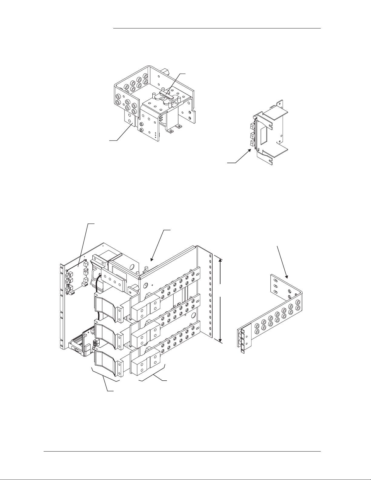
Low Voltage Battery Disconnect
Control card mounted
on left side of cabinet.
CONTACTOR DRIVE BOARD
BOTH SWITCHES DOWN
FORCES CONTACTOR OPEN
CONTACTOR OPEN
CONTACTOR OPEN INITIATED
DOWN FORCES
CONTACTOR CLOSED
REMOTE CONTROL ENABLED
The low voltage battery disconnect (LVBD) feature consists of a
contactor, circuitry on the BJN board, and associated wiring. Control of
the contactor is dictated by the BJN contactor control board and the
controller.
Figure 12-7 shows the location of the contactor control board in the GPS
cabinet.
Typical Battery Panel
For Half Height Cabinets Only
The control card may be mounted
on right side of cabinet.
SW
SW
Red Light
Yellow Light
SW
Green Light
REMOTE CONTROL ENABLED
SWITCH UP FORCES
CONTACTOR CLOSED
CONTACTOR OPEN INITIATED
CONTACTOR OPEN
SW
BOTH SWITCHES UP
FORCES CONTACTOR OPEN
SW
SW
Green Light
Yellow Light
Red Light
Note: All switches should be in the
up position for normal operation.
Note: All switches should be in the
down position for normal operation
Figure 12-7: Low Voltage Battery Disconnect Contactor
Control Switches
Issue 9 Januray 2008 Troubleshooting Preparations 12 - 11
Page 92

Galaxy Power System 4812/24
Reference Figures, continued
AC Input
123456789101112
AC Circuit Breakers for
Rectifiers
through
112
9
10
5
6
1
2
Rectifier
596A2, 596D
12
11
8
7
to Controller
DC Output
Serial Bus Connection
4
3
Rectifier Shelf
AC Input Voltage Range
176Vac - 264Vac
Rectifier Positions
Figure 12-8: Detail of AC Input Panel and Rectifier Shelf
AC Input
12 - 12 Troubleshooting Preparations Issue 9 Januray 2008
Page 93

Galaxy Power System 4812/24
Reference Figures, continued
DC Distribution
Alarm Card
Alarm LED
Figure 12-9: Detail of DC Distribution Panel
Issue 9 Januray 2008 Troubleshooting Preparations 12 - 13
Page 94

Galaxy Power System 4812/24
Reference Figures, continued
Low Voltage Load Disconnect
The EBV low voltage load disconnect (LVLD) contactor control board
is mounted on the right side of the cabinet, as shown in Figure 12-10.
The manual contactor control switch (SW300) is not meant to be used
to permanently override the LVLD function. It is only to be used
temporarily while servicing or testing the equipment.
Control switch mounted
on right side of cabinet.
GREEN LIGHT
REMOTE CONTROL
ENABLED
UP POSITION FORCES
CONTACTOR CLOSED
YELLOW LIGHT ONLY
CONTROLLER SIGNAL
ERROR DETECTED
RED AND YELLOW LIGHT
CONTROLLER SIGNAL
OPENED CONTACTOR
REMOTE
CONTROL
OVERRIDE
SWITCH
Green Light
Yellow Light
Red Light
LOAD DISCONNECT FEATURE IS NOT
FOR USE IN BATTERYLESS SYSTEMS
Note: Switch should be in the
down position for normal operation.
Figure 12-10: Low Voltage Load Disconnect Contactor
Control Switches
12 - 14 Troubleshooting Preparations Issue 9 Januray 2008
Page 95

Galaxy Power System 4812/24
13 Troubleshooting Millennium
Systems
Introduction
In This Section This section provides information for locating and interpreting visual
indicators to help identify problems in Galaxy Power Systems equipped
with the Millennium controller.
Preparation Read Section 12, Troubleshooting Preparations, thoroughly before
proceeding.
Technical Assistance
Note If your cabinet has a metal door and a Galaxy Millennium Controller,
When visual indicators do not identify a defective part, notify Tcyo
Electronics Technical Support.
some components of the controller will look different than in this
manual, but operation is the same.
Issue 9 Januray 2008 Troubleshooting Millennium Systems 13 - 1
Page 96

Galaxy Power System 4812/24
Troubleshooting Tables
Organization The tables in this section are organized alphabetically by Alarm LED,
then grouped according to the status of the alarm: Critical, Major, or
Minor.
Table Reference Use the reference below to locate the Alarm LED and corresponding
table.
Alarm LED Tab le
AC System 13-A, AC Alarms
Battery 13-B, Battery Alarms
Battery on Discharge 13-F, Miscellaneous Alarms
Controller 13-C, Controller Alarms
Distribution 13-D, Distribution Alarms
Rectifier 13-E, Rectifier Related Alarms
Remote Modules 13-F, Miscellaneous Alarms
No LED* 13-F, Miscellaneous Alarms
*If an alarm condition exists, but no alarm LED is lit,
refer to Table 13-F.
Millennium Display Reference
The Millennium display is illustrated below for quick reference while
using the troubleshooting tables.
Galaxy Millennium Controller
Alarm Status
Critical
Major
Minor
Normal
Battery on
Discharge
V
Equipment Status
AC System
Battery
Controller
Distribution
Rectifier
Remote
Modules
Modem
Escape Help
Menu Enter
13 - 2 Troubleshooting Millennium Systems Issue 9 Januray 2008
Page 97

AC System Alarm LED
Controller
LED
AC
System
Controller
Alarm
Statu s
Minor AC Fail ACF on
Galaxy Power System 4812/24
Table 13-A: AC Alarms
(See Figure 12-8)
Millennium
Controller Display
Other
Indication(s)
rectifier
display
Possible
Problem(s)
Rectifier is not
receiving ac
power:
•AC input circuit
breaker has
operated.
•AC input
voltage is out of
range.
•Internal rectifier
failure
Possible Solution(s)
1. Verify that ac circuit
breaker is closed; close
circuit breaker if
operated.
2. If the problem is not
corrected, replace the
rectifier.
AC
System
AC
System
Minor Engine Transfer
Timeout
Minor Phase Alarm PF on
Engine may
have alarm.
rectifier
display
Remote engine
or connection to
engine has
failed.
Phase failure:
•Rectifier high
voltage
shutdown
•External phase
imbalance or
failure
•Internal rectifier
failure
Call technical support.
1. Toggle the ON/STBY
switch into the STBY
position and then back
into the ON position.
2. If the problem is not
corrected, replace the
rectifier.
Issue 9 Januray 2008 Troubleshooting Millennium Systems 13 - 3
Page 98

Galaxy Power System 4812/24
Battery Alarm LED
Table 13-B: Battery Alarms
(See Figure 12-7)
Controller
LED
Battery Critical Very Low Voltage -- Occurs in an operating
Controller
Alarm
Status
Millennium
Controller Display
Other
Indication(s)
Possible Problem(s) Possible Solution(s)
system following an
extended commercial
ac power outage,
during which the
batteries are providing
power for the system
and the system voltage
is approaching the
user-defined low limit.
1. If commercial ac
power is present but
the system voltage
remains low, call
technical support.
2. Investigate other
alarms that may be
present
(rectifier-related
alarms and the AC Fail
alarm may also occur
during the fault
condition).
Battery*
*Alarm
must be
configured
to turn on
the Battery
LED; not a
factory
default.
Battery*
*Alarm
must be
configured
to turn on
the Battery
LED; not a
factory
default.
Battery Minor Open String Alarm LED
Major Contactor 1 Open Red LED on
contactor
drive board is
lit.
Major Contactor 1 Fail -- Contactor or drive
on battery
fuse panel is
lit.
Contactor is open:
•Open has been
initiated by controller.
•Open has been
initiated manually.
board has failed.
Battery fuse has
operated or bat string
switch has opened..
1. Follow instructions on
the label adjacent to
the contactor drive
board (see Figure
12-7).
2. If the problem is not
corrected, call
technical support.
Call technical support.
Replace the operated
fuse.
Battery Minor Low Reserve Time -- Controller has
calculated that battery
reserve time is below
the alarm threshold
level.
13 - 4 Troubleshooting Millennium Systems Issue 9 Januray 2008
Call technical support.
Page 99

Galaxy Power System 4812/24
Controller
LED
Battery Minor Battery Thermal
Controller
Alarm
Status
Millennium
Controller Display
Alarm
Table 13-B: Battery Alarms
(See Figure 12-7)
Other
Indication(s)
Alarm on
210E unit, if
equipped
Possible Problem(s) Possible Solution(s)
Batteries have
exceeded temp
threshold
•Check room ambient
temperature against
battery temperature
threshold
•Call technical support.
Issue 9 Januray 2008 Troubleshooting Millennium Systems 13 - 5
Page 100

Galaxy Power System 4812/24
Controller Alarm LED
Table 13-C: Controller Alarms
(See Figures 12-2 and 12-3)
Controller
LED
Controller Major Controller Fail -- •BSH failure→
Controller
Alarm
Status
Millennium
Controller Display
Other
Indication(s)
Possible
Problem(s)
•BSJ failure
•Option board
failure
•Display failure
•BIC failure
Possible Solution(s)
Check the BSH board to see
if the green LED is
extinguished and the yellow
LED is lit. If so, perform
the following steps:
1. Press the SW200 reset
switch on the top of the
BSH board. If all
diagnostics pass, it is
possible that some type
of “one time”
abnormality occurred to
cause the failure.
2. If the diagnostics did not
pass, or if the problem
recurs, unplug all the
optional circuit board
cables, then press the
reset switch on the top of
the BSH board again. If
all the diagnostics pass,
install optional circuit
board cables one at a
time, verifying operation
after each.
3. If the diagnostics did not
pass, Replace the BSH
board and verify the
failure is resolved. If so,
reinstall the optional
circuit boards and cables
one at a time.
4. If the problem is not
corrected, call technical
support.
13 - 6 Troubleshooting Millennium Systems Issue 9 Januray 2008
 Loading...