

Page 1

GPS2436 (H5692436)
User’s Guide
GPS2436 is available with Galaxy Millennium II or Galaxy Pulsar Plus controllers.
This manual is based on and includes information specific to the Galaxy Millennium II controller.
Refer to these documents for information specific to the Galaxy Pulsar Plus controller
• Galaxy Pulsar Plus Product Manual CC848815341
• GPS2436 Ordering Guide H5692436.
Product Manual
Comcode
850022020
Issue 1
August 2012
Page 2

Notice:
The information, specifications, and procedures in this manual are subject to change without
notice. Lineage Power assumes no responsibility for any errors that may appear in this
document.
© 2012 GE Energy
All International Rights Reserved
Printed in U.S.A.
Page 3

Galaxy Power System GPS2436
Table of Contents
1 Introduction ....................................................................................................... 5
GPS2436 ..................................................................................................................... 5
Customer Service Contacts ........................................................................................ 6
2 System Description ............................................................................................. 7
Overview .................................................................................................................... 7
Architecture ............................................................................................................... 9
3 Galaxy Millennium II Controller ........................................................................ 13
Overview .................................................................................................................. 13
4 Rectifiers .......................................................................................................... 17
NE100AC24ATEZ ...................................................................................................... 17
5 AC Input Panels ................................................................................................ 21
Overview .................................................................................................................. 21
6 Battery Connection Panels ................................................................................ 23
Overview .................................................................................................................. 23
7 DC Distribution Panels ...................................................................................... 25
Function ................................................................................................................... 25
9 External Return Bars ......................................................................................... 33
Overview .................................................................................................................. 33
10 Millennium II Controller Operation ................................................................... 37
Controller Connections ............................................................................................ 39
Installing Circuit Packs ............................................................................................. 40
Thermal Probes ........................................................................................................ 44
USB Interface ........................................................................................................... 44
Local Port ................................................................................................................. 45
Wiring Alarm Outputs .............................................................................................. 45
Wiring Alarm and Control Inputs ............................................................................. 48
Fuses ........................................................................................................................ 51
Front Panel Display .................................................................................................. 51
Controller Defaults ................................................................................................... 55
Controller Display Menu Maps ................................................................................ 62
11 Acceptance Testing ........................................................................................... 74
Introduction ............................................................................................................. 74
Tools and Test Equipment ....................................................................................... 74
Test Precautions ....................................................................................................... 74
Test Sequences ........................................................................................................ 75
12 Circuit Boards ................................................................................................... 83
Overview .................................................................................................................. 83
13 Specifications ................................................................................................... 85
GPS2436 ................................................................................................................... 85
Rectifier .................................................................................................................... 87
3 Safety ............................................................................................................... 90
Safety Statements .................................................................................................... 90
Issue 1 August 2012 3
Page 4

Galaxy Power System GPS2436
14 Maintenance and Replacement ........................................................................ 92
Requirements ........................................................................................................... 92
Rectifier Installation and Replacement Procedures ................................................ 93
15 Troubleshooting Procedure .............................................................................. 94
Preliminary ............................................................................................................... 94
Troubleshooting Procedure ..................................................................................... 95
16 Product Warranty ............................................................................................. 96
Issue 1 August 2012 4
Page 5

Galaxy Power System GPS2436
1 Introduction
GPS2436
Lineage Power developed the Galaxy Power System GPS2436 to support +24 volt
telecommunications powering solutions in worldwide markets. The GPS2436 combines
100-ampere, fan-cooled, switchmode rectifiers, microprocessor control technologies,
battery and load disconnect/reconnect options, and a comprehensive line of fuse and
circuit breaker dc distribution options in a modular front-access design. This modularity
ensures easy access, simplified installation and maintenance, and allows the system to
expand in capacity as power needs grow.
With 2000-ampere maximum capacity, distribution flexibility, and universal ac input
capability, the GPS2436 supports switching, transmission, and wireless applications in
central office locations and environmentally controlled remote sites (huts or vaults).
The main emphasis of this manual is to provide a general product description that will
familiarize the user with the main components of the system and to provide guidelines
for the basic maintenance of this Galaxy Power System.
GPS2436 is available with Galaxy Millennium or Galaxy Pulsar Plus controllers.
Both controllers provide many advanced functions and features, including;
• Alarm Detection, Identification, and Reporting
• System and Component Status
• System and Feature Configuration
• System Alarm Thresholds
• Battery Management (Slope Thermal Compensation/Recharge Current Limit)
• Battery discharge testing
• Reserve Time Prediction
• Float/Boost Mode Control
• Low Voltage Disconnect Management
• Remote Access Control And Multiple Level Password Security
• History
• Statistics
This manual is based on and includes information specific to the Galaxy Millennium II controller.
Refer to these documents for information specific to the Galaxy Pulsar Plus controller
• Galaxy Pulsar Plus Product Manual CC848815341
• GPS2436 Ordering Guide H5692436.
Issue 1 August 2012 5
Page 6

Galaxy Power System GPS2436
Customer Service Contacts
Customer Service, Customer Training, Technical Support, Product Repair and Return, and Warranty Service
For customers in the United States, Canada, Puerto Rico, and the US Virgin Islands,
please dial +1 877 546 3243 (877 LINEAGE) or for all other countries, please call +1 972
244 9288. This number is staffed from 7:00 am to 5:00 pm USA Central Time Zone (GMT
-6), Monday through Friday, on normal business days. At other times, this number is still
available, but for emergencies only. Services provided include initiating the spare parts
procurement process, ordering documents, product warranty administration, and
providing other product and service information.
For other customers worldwide the 800 number may be accessed after first dialing the
direct country code for the country where the call is originating, or you may contact
your local field support center or your sales representative to discuss your specific
needs.
On-Line Power Systems Product Manuals and Software
Power Systems product manuals and software are available on-line. Software includes
Easy View and SNMP MIB.
Issue 1 August 2012 6
Page 7
Galaxy Power System GPS2436
2 System Description
Overview
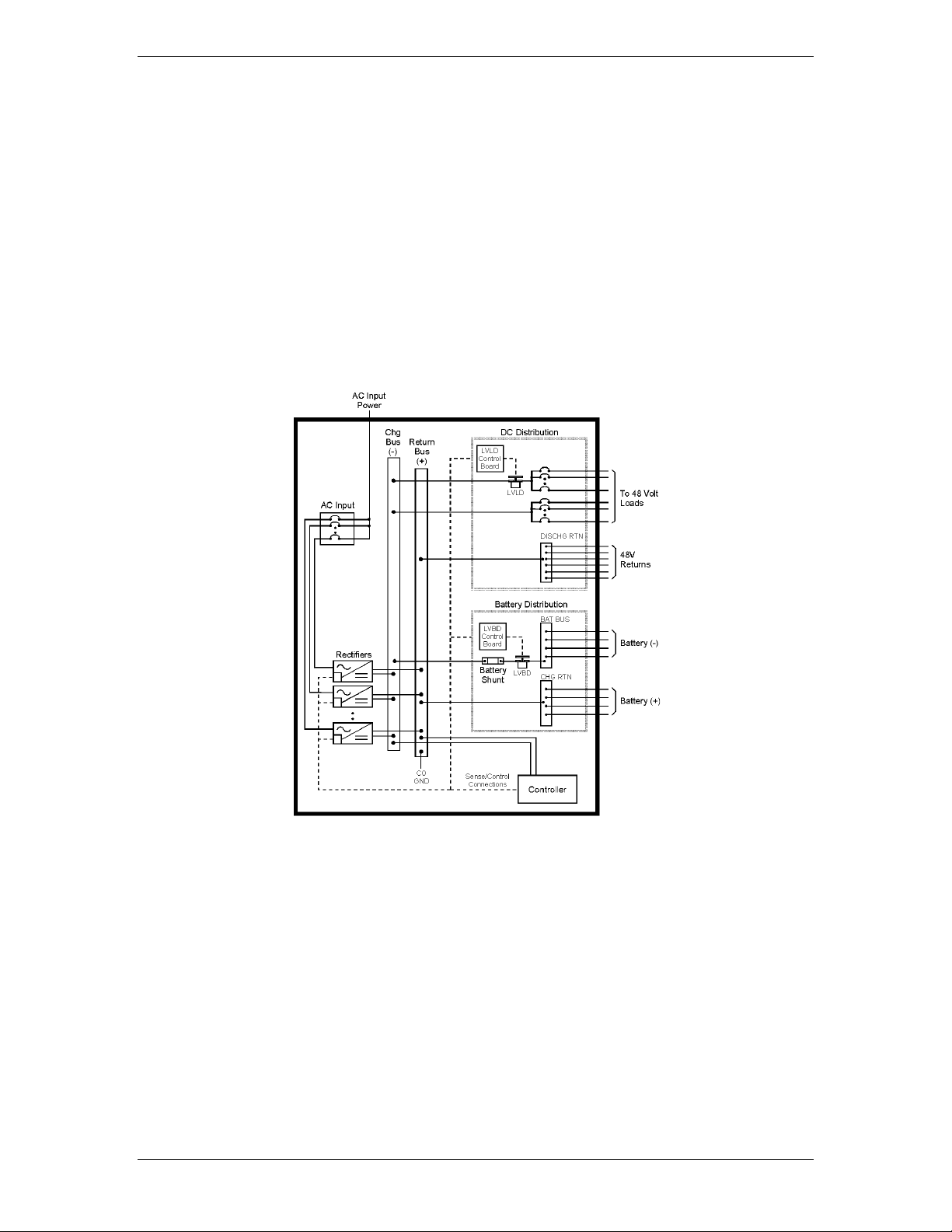
Block Diagram
A basic block diagram of the Galaxy Power System 2436 is shown in Figure 2-1. It illustrates the arrangement and interconnection of the system components from the ac input to the dc output.
Figure 2-1 Block Diagram of the GPS2436
System
The power system accepts alternating current from the commercial utility or a
standby ac power source and rectifies it to produce dc power for the using
equipment. The system’s control and alarm functions interact with the
rectifiers and the office. In addition, the system provides overcurrent
protection and charge, discharge, and distribution facilities. Battery reserve is
connected in parallel and automatically provides a source of dc power if the
commercial or standby ac fails. Battery reserve can be engineered to supply
dc power for a specific period of time. In normal practice, battery capacity is
sized to provide 3 to 8 hours of reserve time.
Issue 1 August 2012 7
Page 8

Galaxy Power System GPS2436
Components
AC Input connects the commercial and/or standby ac power sources to the
rectifiers within the system and provides overcurrent protection. In some
applications the ac service is wired directly to the rectifiers and overcurrent
protection is provided at the service panel.
Rectifiers convert an ac source voltage into the dc voltage level required to
charge and float the batteries and to power the using equipment.
Controller provides the local and remote control, monitoring, and diagnostic
functions required to administer the power system.
Batteries provide energy storage for an uninterrupted power feed to the
using equipment during loss of ac input or rectifier failure.
DC Distribution Panel provides overcurrent protection, connection points for
the using equipment, and bus bars used to interconnect the rectifiers,
batteries, and dc distribution.
Battery Connection Panel provides connection points for the battery strings
through battery disconnect fuses or contactors and current monitoring
shunts.
Issue 1 August 2012 8
Page 9
Galaxy Power System GPS2436
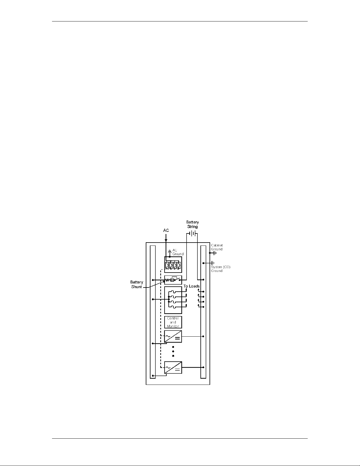
Architecture
Configurations
The GPS2436 is a 7-foot cabinet that can provide up to 3600 amps of DC
power in a single cabinet. Figures 2-1 and 2-2 show diagrams of single
cabinets.
Each cabinet contains ac distribution, dc distribution panels, a battery
connection panel, rectifiers, termination points for load circuits, and a system
controller.
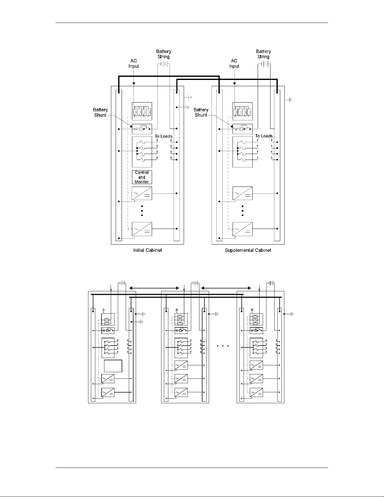
Illustrations
Figure 2-3 shows a block diagram of a two cabinet system. One supplemental
cabinet may be added to grow the system to 2,700 amperes. The rectifier
output buses are interconnected to permit the cabinet to share current and
ensure common voltage references for all system rectifiers.
Figure 2-2 Cabinet schematic
Issue 1 August 2012 9
Page 10
Galaxy Power System GPS2436
Control
and
Monitor
To LoadsTo Loads
Battery
String
Battery
String
ACAC
Controller
Rectifier
Battery
Distribution
Rectifier
Battery
Distribution
Cabinet
Rectifier
Battery
Distribution
Cabinet
AC
Ground
AC
Ground
Cabine
Ground
Cabinet
Ground
To Loads
Battery
String
AC
AC
Ground
Cabinet
Ground
System (CO)
Ground
Shared DC Pow erShared DC Pow er
Figure 2-3 Schematic of two-cabinet system architecture
Figure 2-4 Schematic of Three-cabinet System Architecture
1800A Maximum per system.
Issue 1 August 2012 10
Page 11
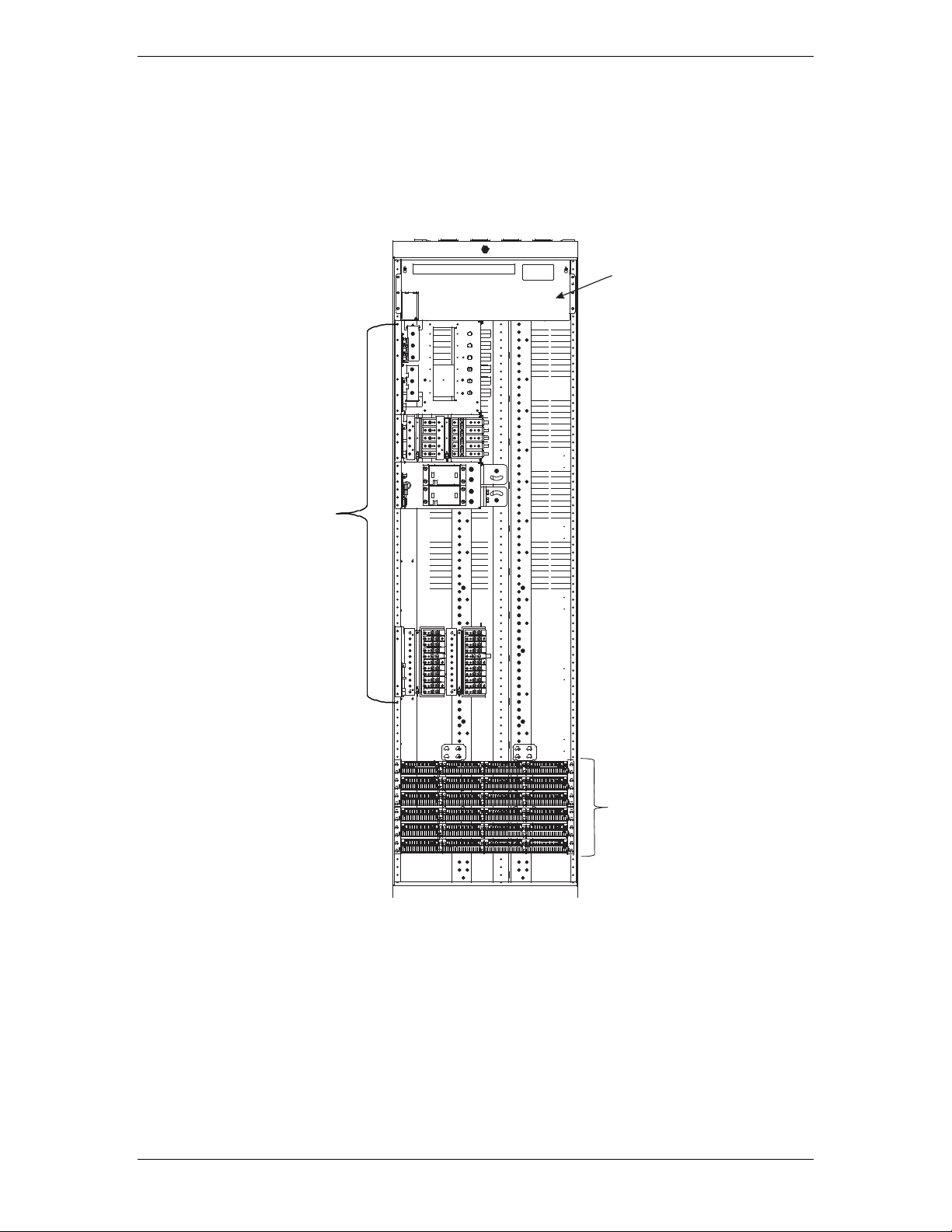
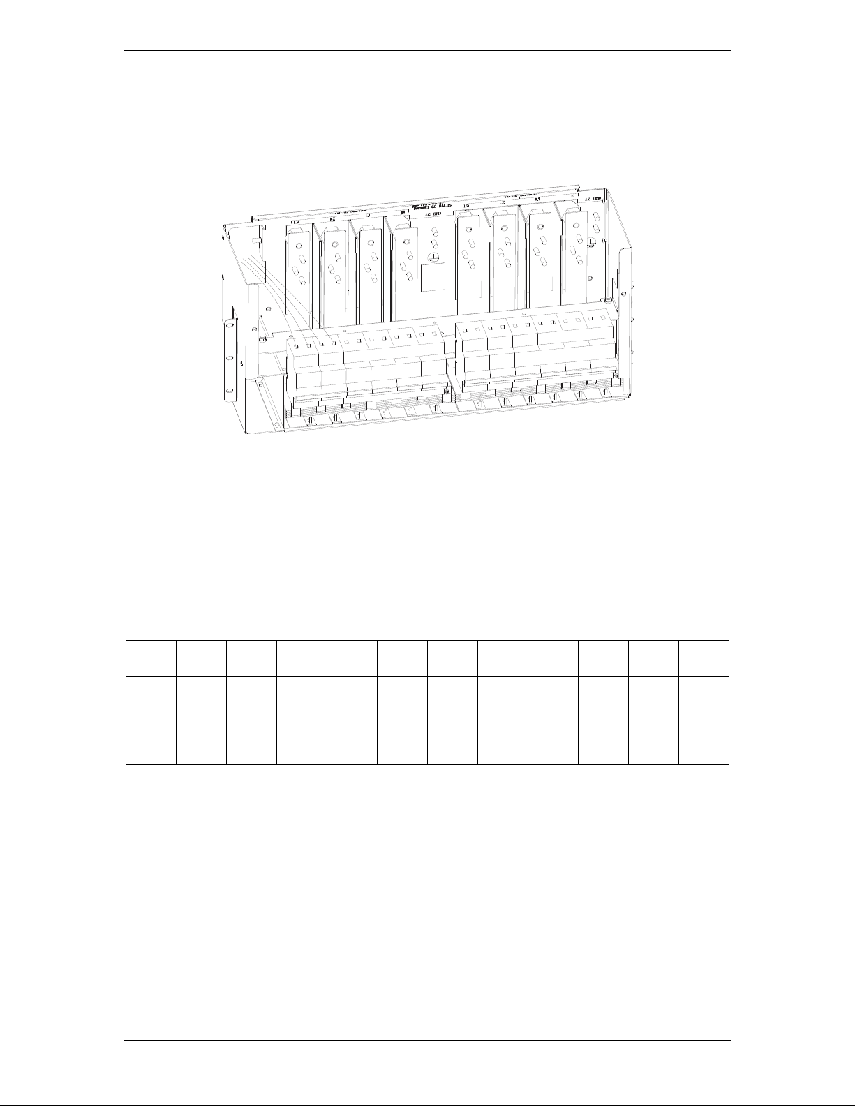
Galaxy Power System GPS2436
AC P anel
Circuit Breakers or
Terminal strip
Rectifier S helves
3 , 6, or 9
Mis cellan eous DC
Distr ibution Panels
Figure 2-4 GPS2436 Six shelf cabinet with door removed
Issue 1 August 2012 11
Page 12

Galaxy Power System GPS2436
This page intentionally left blank.
Issue 1 August 2012 12
Page 13
Galaxy Power System GPS2436
3 Galaxy Millennium II Controller
Overview
Introduction
The GPS2436 comes equipped with the Galaxy Millennium II Controller. This
section describes the controller operation and general information about the
features of the front panel keys, LEDs, and display.
The Galaxy Millennium II Controller provides advanced local and remote
monitoring and data acquisition features. The controller monitors system
parameters; such as, system voltage and current, and components; such as
rectifiers, and distribution circuits. The controller reports the status and issues
appropriate alarms in the event a failure occurs.
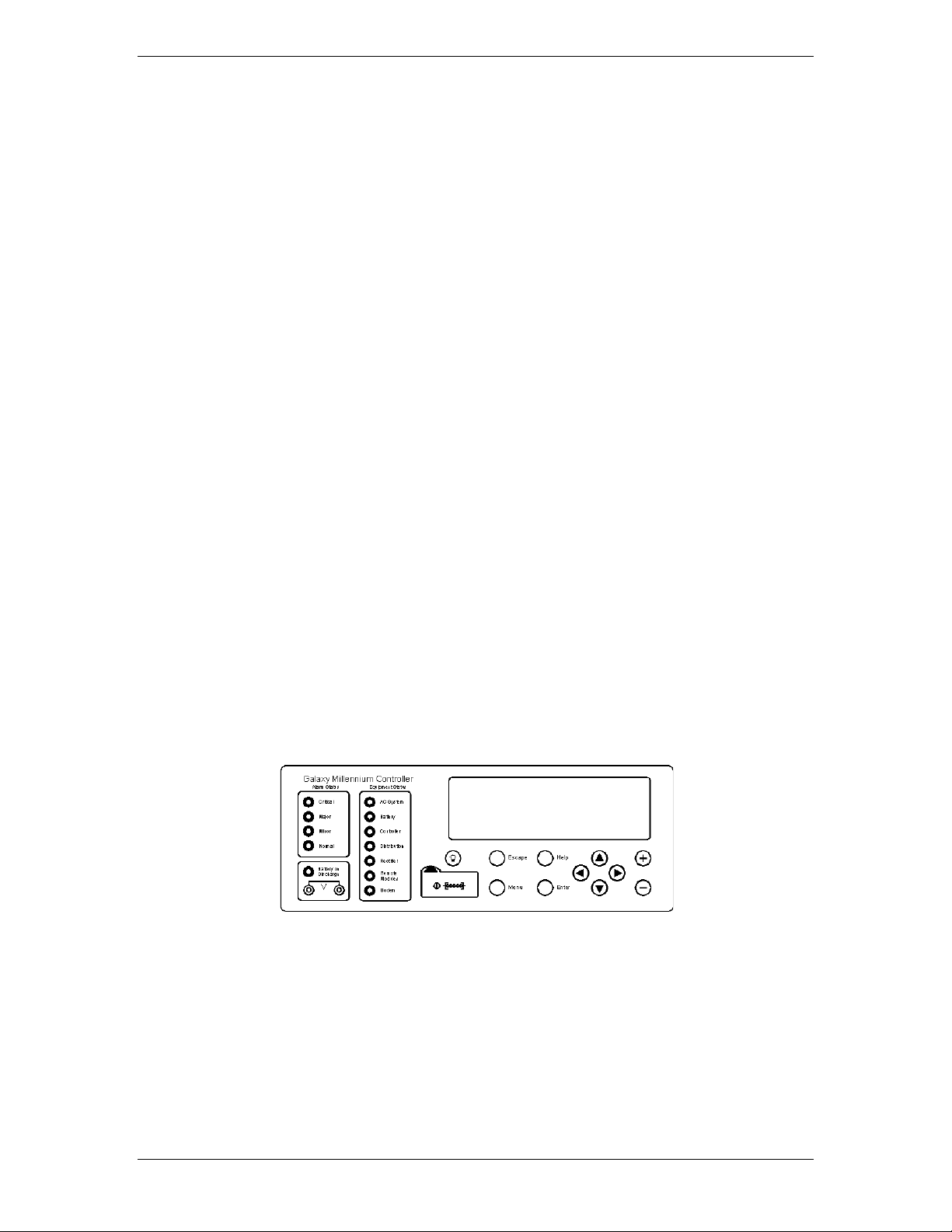
User Interface
and Display
Each cabinet is equipped with a bay interface card (BIC). The BIC acts as an
interface to the cabinet control and alarm signals.
The Millennium II’s primary user interface is a backlit LCD front panel display
that can be viewed in English or Spanish, two rows of LEDs, an array of
pushbutton keys, and a pair of test jacks.
Figure 4-1 illustrates the front panel.
Default Display
The default display shows basic system status; system voltage, load current,
and plant state. The controller returns to this display approximately three
minutes after a key is pressed. The information on the screen is updated
automatically approximately every two seconds.
Issue 1 August 2012 13
Page 14

Galaxy Power System GPS2436
The default screen displays the following: The first line shows the number of
alarms and warnings present in the system, the date, and the time. The next
two lines show the system voltage and the system load. The last line shows
the system mode, which can be one of the following:
• FLOAT
• BOOST
• STC (Slope Thermal Compensation)
• BATT TEST
LEDs
Two rows of LEDs show the source and severity of various alarms. An alarm
lights one status LED and one or more alarm LEDs. If more than one alarm LED
lights, only the status LED of the most severe alarm will light.
• The first row includes four LEDs, labeled Alarm Status. They indicate the
severity of the reported alarm:
Test Jacks
Critical
Major
Minor
Normal
The Battery on Discharge LED is also in this row.
• The second row has seven LEDs, labeled Equipment Status. They
indicate the source of the alarm:
AC System
Battery
Controller
Distribution
Rectifier
Remote Modules
The Modem LED illuminates when the internal modem is in use.
A pair of test jacks allows direct measurement of the dc bus sense voltage
being monitored by the controller.
Issue 1 August 2012 14
Page 15

Galaxy Power System GPS2436
Pushbutton Keys
A group of pushbutton keys below the backlit LCD display provides the
primary user interface with the controller. These keys are used singly or in
combination to navigate through the controller’s menus.
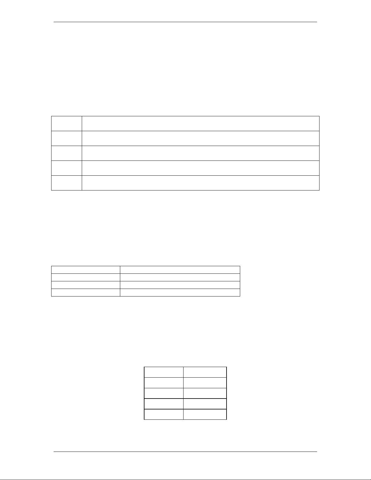
The following is a general description of the pushbutton keys:
• ESCAPE: Return to the immediate higher level menu.
• HELP: Displays limited on-line help information.
• MENU: View the MAIN menu.
• ENTER: Select a menu item.
• Up arrow: Moves the cursor up one line.
• Down arrow: Moves the cursor down one line.
Access Panel
• Left arrow: Moves the cursor left one field.
• Right arrow: Moves the cursor right one field.
• + and -: Increase or decrease parameter values.
• Lamp test: Tests the controller’s circuit board LEDs and front panel LEDs. It will
also test the indicators of serially connected rectifiers.
A rubber flap can be opened to access the local port connector. The DB-9 local
port connector supports standard RS232 serial communication. Refer to the
Galaxy Millennium II Controller product manual for additional details on port
configuration and isolation.
Issue 1 August 2012 15
Page 16

Galaxy Power System GPS2436
Reference Material
Controller Product
Manuals
The Galaxy Millennium II Controller product manual (Comcode 108994645) is
available. Refer to this manual for information regarding configuration and
operation.
RPM System
Product Manual
Refer to the Galaxy Remote Peripheral Monitoring System product manual
(Comcode 107570517) for additional information regarding RPM module
operation.
Issue 1 August 2012 16
Page 17

Galaxy Power System GPS2436
4 Rectifiers
NE100AC24ATEZ
Overview
The NE100AC24ATEZ Series rectifier (100A) operates from single-phase ac
service with a phase-to-phase voltage within the range of 95-275Vac.
The rectifiers are shipped separately from the cabinets for quick and
straightforward installation into rectifier shelves at the site. Interconnections
to ac input, dc output, and control signals occur automatically during
insertion. No settings or adjustments to potentiometers are necessary.
The NE100AC24ATEZ rectifiers are UL Recognized for both the U. S. and
Canada, comply with UL1950 (Information Technology Equipment), and meet
EN60950 requirements.
Front Panel Display
Status Indicators
Three LEDs on the rectifier’s faceplate indicate the rectifier’s condition.
• The Norm LED is green and is lit when the rectifier has AC input present and is
working properly.
• The ACF LED is amber and is lit when there is no AC input present to the
rectifier.
• The Fail LED is red and is lit if there is a failure in the rectifier.
Lamp Test
To test the LEDs on the rectifier front panel, press the Lamp Test button on
the controller.
Issue 1 August 2012 17
Page 18

Galaxy Power System GPS2436
Features
Output Current “Walk-in”
This circuit controls the time (up to eight seconds) required for the rectifier to
reach normal operating conditions after it is turned on. This feature minimizes
the starting surge on the customer's power source.
Output Protection
Rectifier is equipped with an internal fuse for plant protection if a fault occurs
in a rectifier.
Electronic Current Limit
When the output current tends to increase above the current limit set point,
the current limit circuit overrides the voltage regulating signal and safely limits
the output current of the rectifier, thus preventing damage to itself or the
load.
High Voltage Shutdown (HVSD)
The rectifier senses the voltage at its output terminals. If this voltage is too
high, the rectifier will shut down to prevent the high voltage from damaging
itself or the load.
Restart
Upon shutdown, the rectifier will attempt to restart. The rectifier will also
accept a restart command from the controller for a remote restart. The
rectifier will attempt to restart three times before issuing a rectifier fail alarm
to the controller.
Fan Alarm and Control
The rectifier contains a cooling fan. The fan’s speed, which is based on
ambient temperature and output power level, is lowered during low-load and
low-temperature conditions to minimize audible noise and maximize fan life.
Issue 1 August 2012 18
Page 19

Galaxy Power System GPS2436
Thermal Alarm
The rectifier senses the internal operating temperature and will issue a
thermal alarm if the internal temperature exceeds a safe operating level.
Ambient temperatures above the maximum rating will result in a rectifier
shutdown and the issuing of a thermal alarm (TA).
Autonomous Operation
Rectifiers will continue to power the load if the controller fails or if
communication is lost.
Controller Communications Alarm
When communications between the rectifier and controller are interrupted,
the rectifier continues to operate and the red Fail LED on the rectifier blinks.
Connectorized
“Forced” Load
Sharing
The rectifiers provide the controller with a full complement of status and
alarm signals. The rectifier status and alarm signals, ac input, and dc output
are all connectorized for easy installation and maintenance. System
connections are made when the rectifier is plugged into the shelf. No
additional connections are required.
Internal rectifier circuitry will allow rectifiers to share load in the event
communication to the controller is lost or the controller malfunctions.
Issue 1 August 2012 19
Page 20

Galaxy Power System GPS2436
This page intentionally left blank.
Issue 1 August 2012 20
Page 21

Galaxy Power System GPS2436
Figure 6-1: AC Input Terminal strip Panel
5 AC Input Panels
Overview
AC Service
The ac input panel provides the facility to terminate 3-phase ac service to the GPS2436 system
or to distribute individual 1-phase ac supplies to each of the system rectifier positions.
Depending upon the option ordered, the panel will connect 3-wire (three phases), 4-wire (three
phases + neutral), or individual 2-wire (single phase, either 2 hot leads or 1 hot lead and neutral)
input ac service.
Some options provide circuit breakers to protect the conductors providing ac service to the
individual rectifiers. Other systems contain a terminal strip and the conductors are protected by
circuit breakers located in the building’s ac service panel.
Note: All wire sizes based on the US National Electric Code.
Figure 5-2: AC block.
Factory wiring from AC block to rectifier shelf shown.
Issue 1 August 2012 21
Page 22
Galaxy Power System GPS2436
Figure 6-3: AC Input circuit Breaker Panel
CB1
CB2
CB3
CB4
CB5
CB6
CB7
CB8
CB9
CB10
CB11
CB12
G11
G12
G21
G22
G31
G32
G41
G42
G51
G52
G61
G62
G13
G14
G23
G24
G33
G34
G43
G44
G53
G54
G63
G64
Figure 6-4: AC circuit breaker wiring and rectifier positions
Issue 1 August 2012 22
Page 23

Galaxy Power System GPS2436
6 Battery Connection Panels
Overview
Function
Batteries are connected to the GPS2436 cabinets on battery connection panels located in the
cabinet directly below or behind the ac input panel. All panels include the battery shunt and an
alarm card that communicates with the controller to provide battery current and status
information. The panel includes a low voltage battery disconnect/reconnect (LVBD/R) contactor.
When equipped with contactors, a contactor control card provides local/manual control of the
contactors and a shunt to monitor battery charge/discharge current.
Illustrations
Battery connection panel is shown in Figures 7-1.
Note: Battery connection panels are blue; dc distribution panels are white.
Issue 1 August 2012 23
Page 24
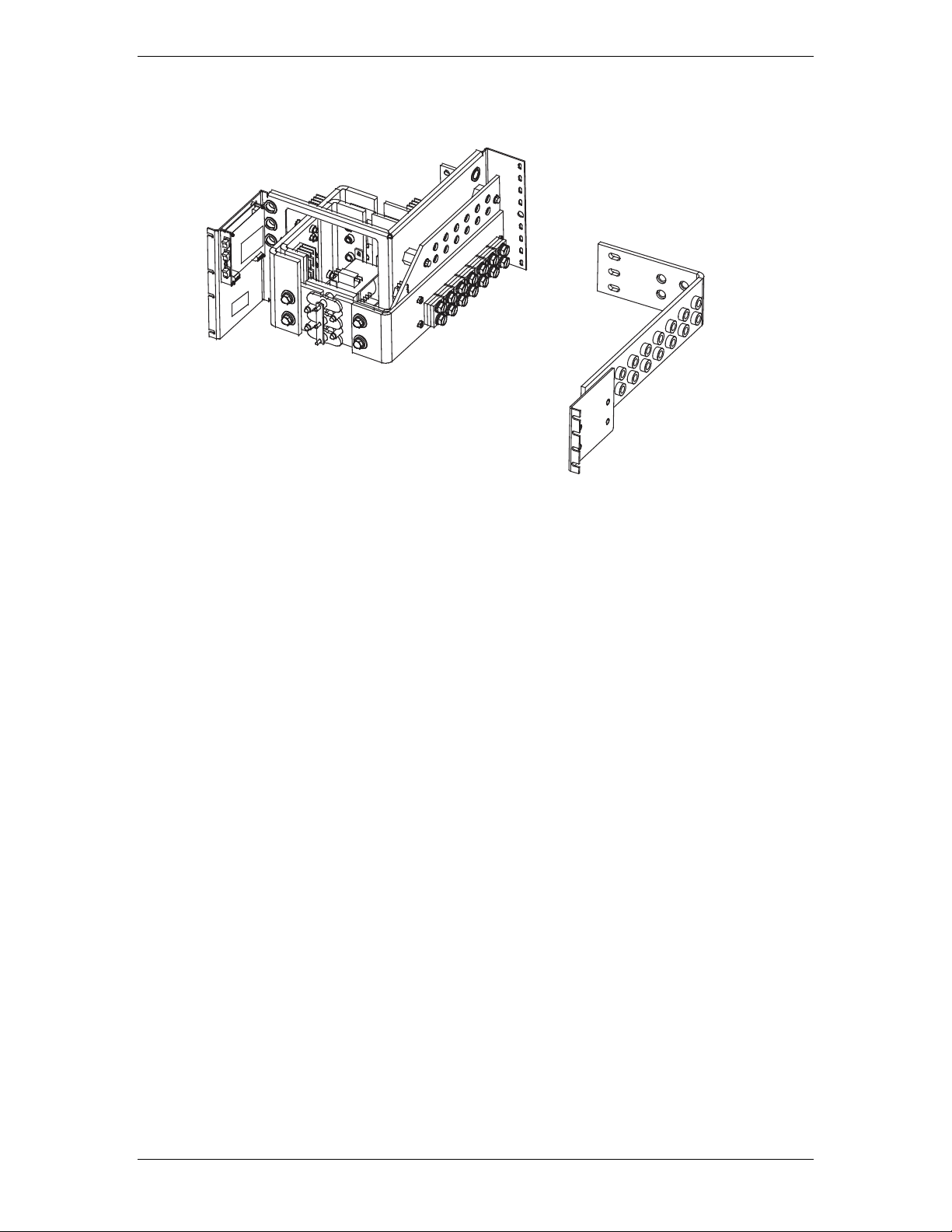
Galaxy Power System GPS2436
Figure 6-1: H5692436 G39 (ED83143-31 G36)
Panel is equipped with a Low Voltage Battery Disconnect/Reconnect contactor rated at
2000 amps, and a 3000 amp shunt to monitor battery charge/discharge current.
Issue 1 August 2012 24
Page 25

Galaxy Power System GPS2436
7 DC Distribution Panels
Function
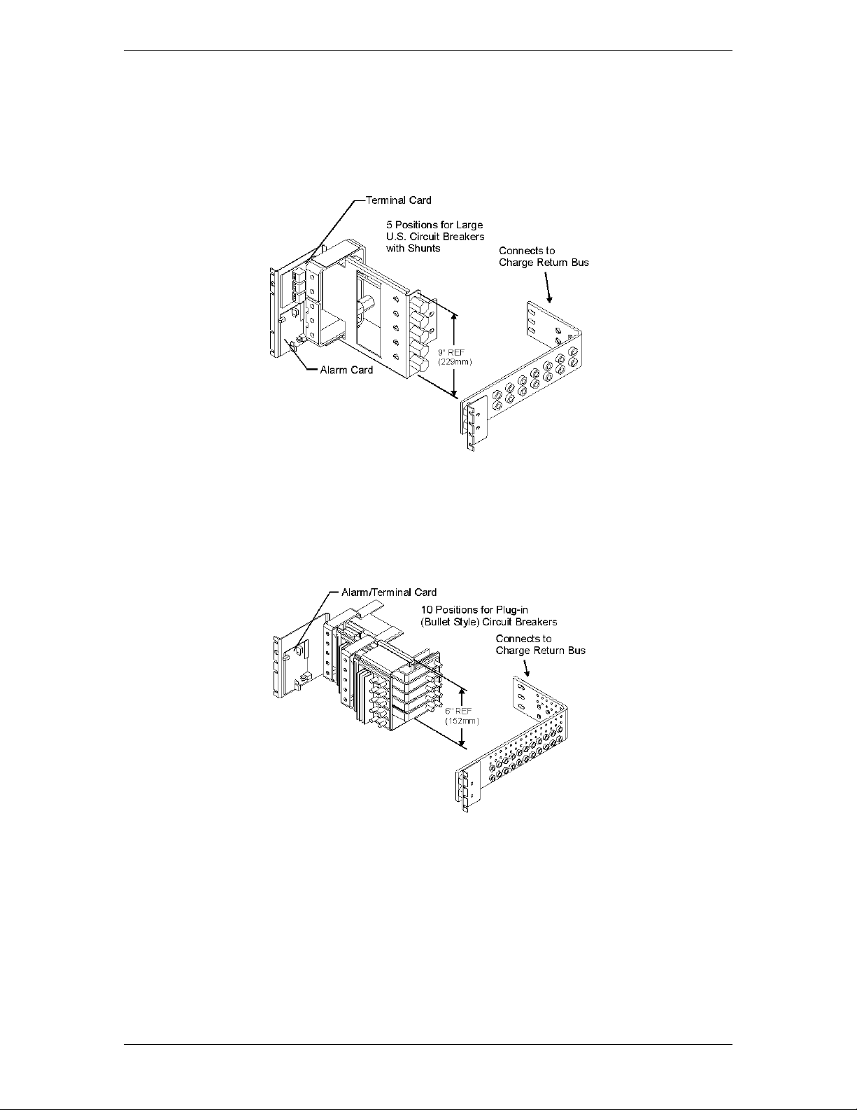
A variety of dc distribution panels is available for the GPS 4827 system, including DIN standard
fuse holders and circuit breakers and U. S. standard fuse holders and circuit breakers. All panels
are equipped with an alarm card. When a fuse operates or a circuit breaker trips, a red LED on
the alarm card lights, the cabinet alarm lights, and the alarm is transmitted to the controller.
Distribution panels are also available with contactors to provide low voltage load disconnect.
Illustrations
The dc distribution panels are illustrated in Figures 7-1 through 7-11.
Note: DC distribution panels are white; battery connection panels are blue.
Note: DC distribution panels are white; battery connection panels are blue.
Issue 1 August 2012 25
Page 26
Galaxy Power System GPS2436
Figure 7-1: H569-4827 G42 (ED83143-31 G2)
Figure 7-2: H569-4827 G43 (ED83143-31 G1)
DC Distribution Panel
DC Distribution Panel
Issue 1 August 2012 26
Page 27
Galaxy Power System GPS2436
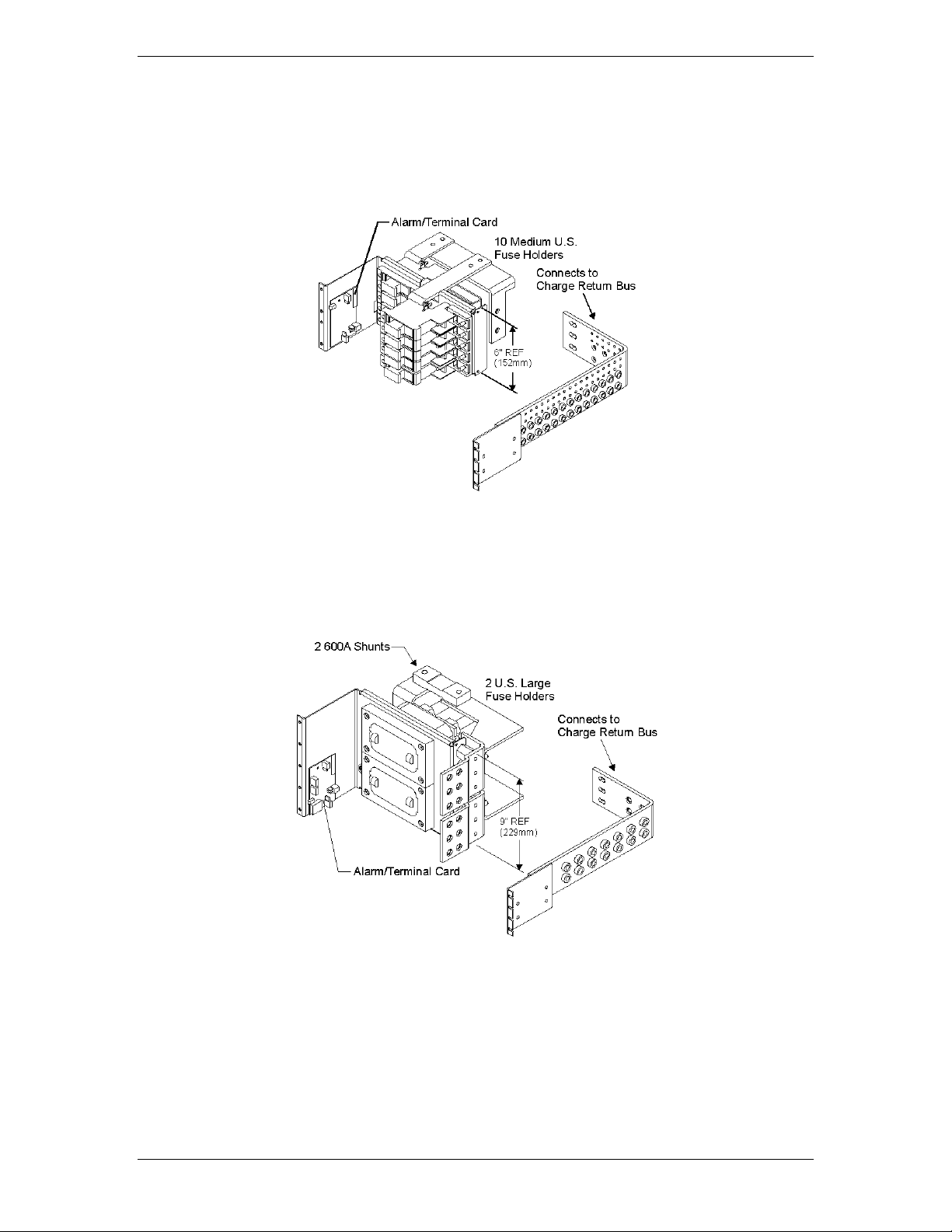
Figure 7-3: H569-4827 G48 (ED83143-31 G5)
Figure 7-4: H569-4827 G96 (ED83143-31 G15)
DC Distribution Panel
DC Distribution Panel
Issue 1 August 2012 27
Page 28
Galaxy Power System GPS2436
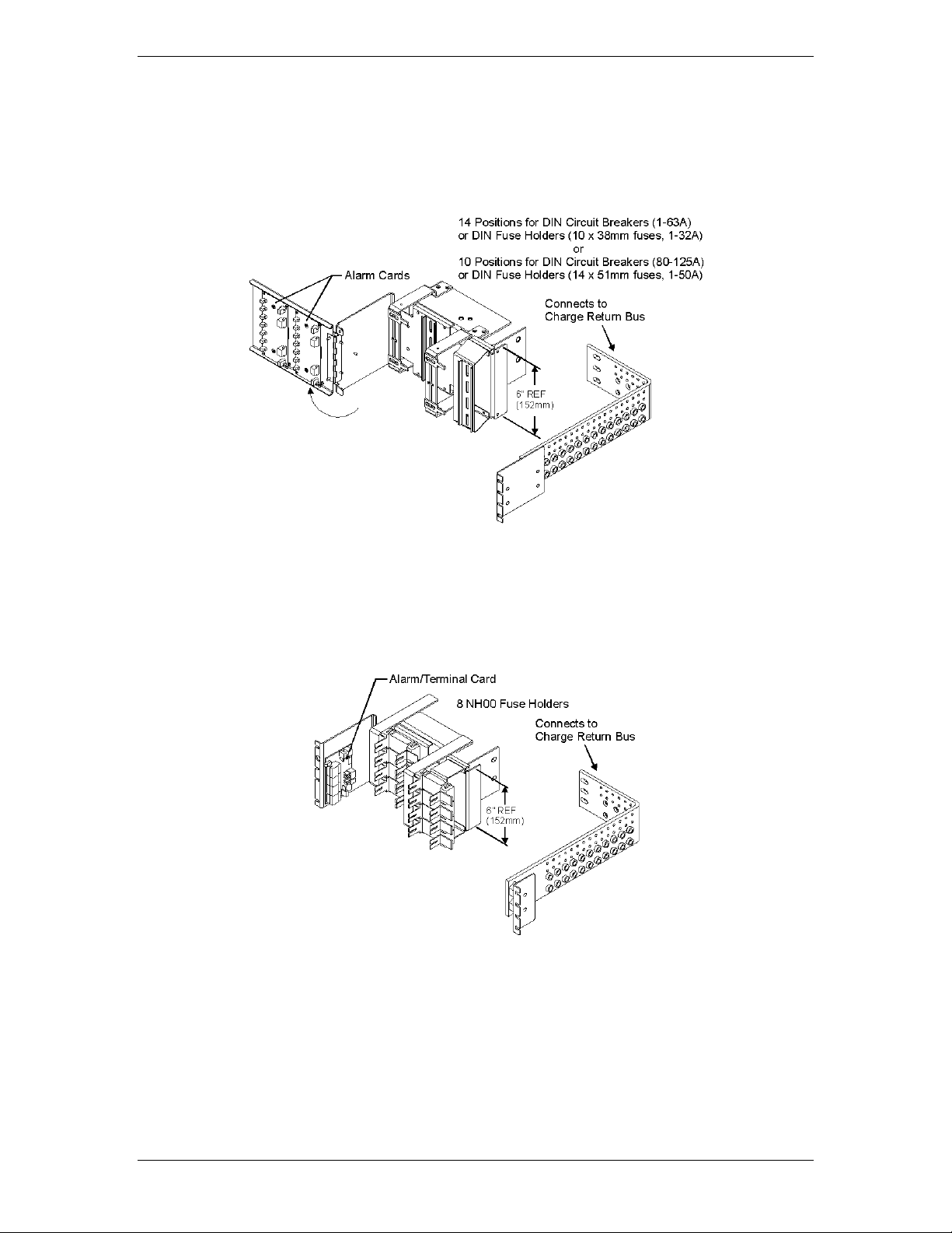
Figure 7-5: H569-4827 G52 (ED83143-31 G53)
Figure 7-6: H569-4827 G53 (ED83143-31 G55)
DC Distribution Panel
DC Distribution Panel
Issue 1 August 2012 28
Page 29
Galaxy Power System GPS2436
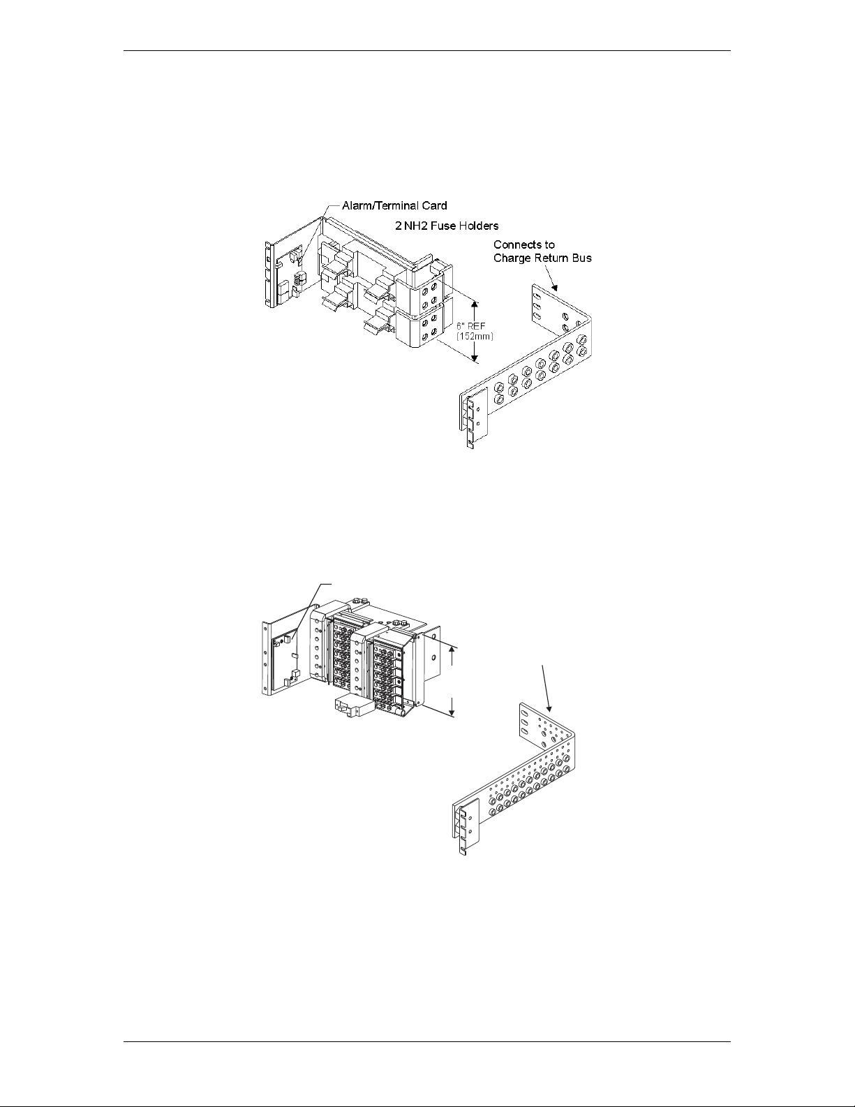
Figure 7-7: H569-4827 G60/61/65/66 (ED83143-31 G71)
Figure 7-8: H569-4827 G67 (ED83143-31 G22)
DC Distribution Panel
DC Distribution Panel
Issue 1 August 2012 29
Page 30
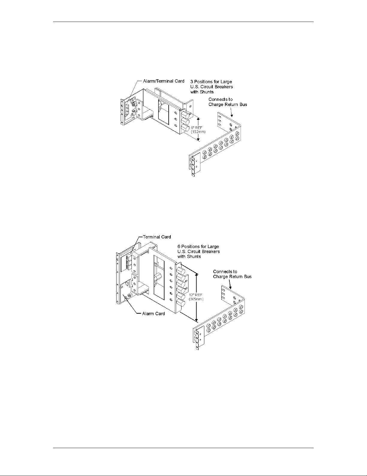
Galaxy Power System GPS2436
Alarm/Terminal Card
Connects to
Charge Return Bus
G97: 6" R EF (152m m )
G98: 9" R EF (229m m )
Figure 7-9 H569-4827 G68 (ED83143-31 G21)
DC Distribution Panel
Figure 7-10 H569-4827 G97, G98 (ED83143-31 G17)
DC Distribution Panel
Issue 1 August 2012 30
Page 31

Galaxy Power System GPS2436
300A Shunt (in back
of panel) per Pos ition
5 Large TPL-B
Fus e Positions
9" REF
(229mm)
Connects to
Charge Return Bus
Alarm/Terminal Card
Maximum Panel Capaci ty
1125A
800A with LVLD
Shunt Monitoring Connection
Points to RPMs
6" REF
(152mm)
TPL-C Fuse Head Furnished with Block.
Order 408472322 TPL-B Fuse
Bloc k Head for 70A - 250A Fuses.
Connects to
Charge Return Bus
Figure 7-11 H569-4827 G54 (ED83143-31 G21)
DC Distribution Panel
Figure 7-12 H569-4827 G59 (ED83143-31 G21)
DC Distribution Panel
Issue 1 August 2012 31
Page 32

Galaxy Power System GPS2436
This page intentionally left blank.
Issue 1 August 2012 32
Page 33

Galaxy Power System GPS2436
8 External Return Bars
Overview
Modular external return bus bar kits are available for the GPS2436 system. These kits are
alternatives to the standard internal return buses. These kits allow for modular growth of the
bars from bay to bay and offer additional cable landings.
Illustrations
External return bars are illustrated in Figures 8-1 through 8-3.
Figure 8-1 Standard Architecture 600mm External Return Bus Kit
CC848805160 for distributed architecture cabinets
Issue 1 August 2012 33
Page 34

Galaxy Power System GPS2436
CC109170511 Standard Bay CC109170197 Wide Bay
Modular Distribution Bay Overhead Buses
CC109170180 Modular Rectifier Bay Overhead Bus
Figure 8-2 Horizontal Rectifier Standard and
Wide Distribution Bay bus bar system
Issue 1 August 2012 34
Page 35

Galaxy Power System GPS2436
CC109170412 Modular Distribution Wide Bay Overhead Bus
Field Option A Field Option B
CC109170404 Rectifier Bay Overhead Bus
Wide distribution bay return bus bar systems
Figure 8-3 Vertical rectifier standard and
Issue 1 August 2012 35
Page 36

Galaxy Power System GPS2436
This page intentionally left blank.
Issue 1 August 2012 36
Page 37

Galaxy Power System GPS2436
The following
•
installed.
But BEFORE:
• Connecting the batteries to the plant charge and discharge bus
bars or turning up the plant rectifiers.
Observe ESD protection while installing circuit packs.
Wear grounded antistatic wrist straps when handling all circuit packs. The wrist strap
must contact the skin and is not to be worn over clothing.
Never hand a circuit pack from a grounded to a non-grounded person or vice-versa.
9 Millennium II Controller Operation
The Millennium II is factory pre-installed and pre-configured with industry standard
defaults for thresholds and feature operability in GPS cabinet applications. In addition,
customer specific default controller settings may be available upon request. This
section provides:
Preparation and Precautions
Procedures for the proper addition of optional packs
Input and output wiring to the controller and the installation and
wiring of optional features
Controller default configuration information such as alarm severity
and description, system voltage, shunt information
Controller configuration information
Preparation
Installation
procedures
should be
performed
AFTER:
Precautions
All the equipment frames (initial and supplemental bays, freestanding rectifiers, etc.) are anchored in place.
• The battery stands have been erected and the batteries
installed.
• The overhead cable racks have been installed and the power
cables have been run and terminated.
• The plant’s charge and discharge bus bar assemblies have been
Issue 1 August 2012 37
Page 38

Galaxy Power System GPS2436
Action
Verified
Always consider personal safety before beginning any procedure.
Review the Safety section.
Be aware of the presence of unfused battery potential in the vicinity of
the controller.
Use only insulated tools.
Make sure the system is properly grounded per the National Electrical
Code and local building codes.
Remove all metal jewelry before beginning the installation.
Item
Verified
Wire cutters and strippers
18 to 22 AWG wire
Jewelers screwdriver (Flat and Phillips)
Small needle nose pliers
Digital meter, +/- 0.02%
Screw Drivers (flat-blade and Phillips)
ESD wrist strap
Wire-wrap tool or Amp alarm punch-down tool
Safety
Installation Materials
Figure 9-1: Millennium II
Issue 1 August 2012 38
Page 39

Galaxy Power System GPS2436
Reference
Description
P2
10/100 Base-T LAN/Ethernet interface
P3
Connectorized interface for 10K/30K thermistor probe options or 210E
Major Fuse alarm (Same connection as on the Millennium)
monitoring devices
P9
RJ45 receptacle for isolated RS485 system component monitoring and control of rectifiers,
bus)
P15
Connectorized interface for future smaller serial format LCD
P205
Option board connector
(RPM) connections
options
Controller Connections
Figure 9-2: Millennium II Controller Connections
Table 9-A: Millennium II Interface Reference
Interface
P1 Connectorized interface for large parallel format 8x40 LCD assembly
P6 Connectorized input for input power, monitoring of two shunts, plant sense voltage, and
P7 RJ45 receptacle for ground referenced Auxiliary RS485 circuit and One-Wire temperature
P8 BSL1-4 circuit pack Interface connector for Input/Output to controller
converters, low voltage disconnect contactors, and bay level alarm inputs (Serial Rectifier
P13 Factory test connector (not used in the field)
P14 Connectorized interface for future smaller serial format LCD
P201 Connectorized interface for optional Modem
P202 Ground referenced DB-9 for local RS232 serial port
TB1 Terminal block interface for RS232/RS485 Auxiliary port and Remote Peripheral Module
TB2 Terminal block interface for three additional 10K thermistor probe or 210E connection
J10 USB interface (reserved for future use)
Issue 1 August 2012 39
Page 40

Galaxy Power System GPS2436
Step
Action
NOTE:
Installation or replacement of this pack can be done “hot”; power removal is not
Note: This step may be performed at a later time
Controller Reset is to the right of the serial connector.
Installing Circuit Packs
Figure 9-3: Millennium II Controller Connections
Modem Card
The optional Modem card may require field installation. To do so, perform the following
steps:
necessary.
1. Remove the controller front cover.
2. Install the BSM on the 4 standoffs, to left of the controller MCR1 board using
four 845143866 screws.
3. Connect the 848091798 cable assembly between the BSM J100 plug and P201
on the MCR1 board.
4.
Install phone line wiring from Connect the existing telephone cable to the RJ11
connector at the top of the board
OR
Connect Tip/Ring conductors to TB1 at the top of the board.
NOTE: Tip is TB1 pin 1 (Pin closest to the RJ11 connector) and Ring is Pin 3. Pin 2
is not used.
5. Operate the reset switch on the MCR1 board in the lower left corner of the
MCR1 board. (see Figure 4-3)
NOTE: The Password Reset button is to the LEFT of the serial port connector, and the
Issue 1 August 2012 40
Page 41

Galaxy Power System GPS2436
Step
Action
is not necessary.
procedures.
seated.
6.
Secure the alarm board at the top using the two screws removed earlier.
Data Switch Card
NOTE: Installation or replacement of this pack can be done “hot”; power removal
2. Install two 407882133 standoffs on the BSJ intelligent board. Screw threads
are protruding just below TB1, located at the upper left hand corner of the
MCR1 board.
3. Place BSW pack inside the 847950938 insulator.
4. Plug BSW pack into the P205 connector on the BSJ intelligent controller
board
5. Secure the BSW board to the standoffs with two 900562208 screws.
NOTE: To install the Data Switch Extension board, please see the User’s Guide for
Millennium II Controller Advanced Features manual.
Alarm Termination Board
Alarm Termination board options provide for wire wrapped or insulation displacement
(punch down) terminations. The Alarm Termination Board for a specific application may
require field installation. To do so, perform the following steps:
Step Action
1. In the upper right hand corner of the MCR1 board, find the alarm board
already installed.
2. Remove the two screws holding the board at the top.
3. Holding the board on both sides, slowly, but firmly, remove the alarm board
from the P8 connector.
4. Unpack the new board from its box, carefully observing proper ESD
5. Connect the alarm board to P8 and press down firmly, until the board is
Issue 1 August 2012 41
Page 42

Galaxy Power System GPS2436
1.
At the controller, connect one end of the network interface cable to P2.
the User’s Guide for Millennium II Controller Advanced Features manual.
NOTE:
For new installations, the Millennium II rectifier cabling has been factory
properly.
2.
Verify that the cable connector is properly seated into P9, and that it is not
RPM provides data acquisition capability far beyond that normally available in a power
The user may connect a maximum of 95 of any combination of these modules serially.
Gateway (LAN) Connections
Step Action
NOTE: The Gateway card has been designed into the MCR1/MCR2 boards and
requires no additional circuit packs.
NOTE: The Gateway has an IEEE 802.3 compliant 10Base-T network interface.
Since the cable length required to connect to the network is variable, this
cable must be supplied by the user.
This connector is located at the bottom center of the MCR1 board, and
immediately below the MCR2 board.
2. Connect the other end to an IEEE 802.3 compatible network.
3. Configure the Gateway for the network by contacting the customer’s
network administrator. Detailed configuration information may be found in
Rectifier Cabling
Step Action
wired and installed to the cabinet BIC/BLJ board for alarm and rectifier
communication.
NOTE: For connector integrity, verify that the cable is installed and connected
1. Verify that the rectifier cable is connected to P9, and NOT P7(AUX) cable
connector.
loose.
3. Verify that the rectifier cable terminating on the BIC/BLJ board is connected
to P9 and also not loose.
Remote Peripheral Monitoring (RPM)
system controller. Monitoring modules available consist of:
• Shunt monitors (6 channels + 1 temperature channel)
• 0-100mV dc Voltage monitors (6 channels + 1 temperature channel)
• 0-3V dc Voltage monitors (6 channels + 1 temperature channel)
• 0-16V dc Voltage monitors (6 channels + 1 temperature channel)
• 0-200V dc Voltage monitors (6 channels + 1 temperature channel)
• Temperature monitor (7 Channels)
• Control Relay module (3 sets of programmable form C relay outputs)
Issue 1 August 2012 42
Page 43

Galaxy Power System GPS2436
Step
Action
NOTE:
The Remote Peripheral Monitoring feature has been designed into the
Advanced Features manual.
Using the RPM bus cable (comcode 407377704), wrap the cable through the
Color
6
*6
Blue or White
Power/Communications
8
*8
Blue or White
Power/Communications
faced bottom of the connection unit.
4.
Make the connections to TB2 on the connection unit:
TB-2 Pin
RPM
RPM Conductor
SHIELD
Bare wire
Shield
In the lower right hand side of the control unit (inside), are two rotary
1 (LO) to 1. The module will be recognized as 01 by the
Carefully attach the control unit to the connection unit using the ribbon
MCR1 board and requires no additional circuit packs. Monitoring and
control modules ARE required, based on the application.
NOTE: This section only describes a single module connection to the controller.
Modules MUST BE PROGRAMMED after they have been installed or they
may not function properly. Detailed connection and configuration
information may be found in the User’s Guide for Millennium II Controller
1.
EMI inductor bead twice. Place the bead approximately 3 inches from the
end of the cable.
2. Connect the bus cable to:
TB-1 Pin
Assignments
TB-1 Pin
Descriptions
RPM
Conductor
RPM Conductor
Description
9 or 10 FGND Bare wire Shield
*connections of the bus wire are NOT polarity sensitive.
3. Secure the module connection unit and route the wires through the open-
Assignments
Conductor
Description
Color
IN Blue or White Power/Communications
OUT Blue or White Power/Communications
*connections of the bus wire are NOT polarity sensitive.
* there are 2 IN, and 2 OUT connections. Either one may be used.
5. Locate the control unit. This is the half with circuitry on it.
6.
switches. Set SWcontroller. Other modules added cannot have the same address or 00 for
the address.
7.
connector.
NOTE: This connector/cable is not keyed, so be careful to line up the pins properly.
Issue 1 August 2012 43
Page 44

Galaxy Power System GPS2436
8.
After approximately 1 minute, the green LED on the front of the module will
blink once approximately every 5 seconds. Detailed troubleshooting
information may be found in the User’s Guide for Millennium II Controller
Advanced Features manual.
Without thermal probes, many of the controller’s battery management features will not
High Temperature Disconnect
Location
10/30K
P3
Mux
1 Wire Temperature
P7
Pin
Description
1
Probe 2
6
Probe 4 RTN
This interface is reserved for future use.
Thermal Probes
function, or produce erroneous results. Some features requiring thermal inputs are:
• Slope Thermal Compensation
• Reserve Time Prediction
• High Temperature Alarm
• Ambient High and Low Temperature Alarms
•
Step Action
NOTE: The controller supports a number of thermal probe inputs. The type of
probe used determines where it is connected on the controller. Detailed
thermal probe and battery management information may be found in the
User’s Guide for Millennium II Controller Advanced Features manual.
1. The following table shows the type of probe and connector location on the
Millennium:
Type of Probe Comcode
210E Thermal Probe
P3
Controller Connection
Monitoring Devices
Terminal Block
TB2
Interface for 3
additional 10k probes
or 210E connection
2 Probe 2 RTN
3 Probe 3
4 Probe 3 RTN
5 Probe 4
USB Interface
Issue 1 August 2012 44
Page 45

Galaxy Power System GPS2436
Form-C Alarm Contact Ratings
60Vdc, 0.3A
integrity)
Pin
Number
Signal Name
Pin
Number
Signal Name
Pin
Number
Signal Name
1
PCRAO
33
MJFR
65
FAN
2
PCRAC
34
MNFR
66
AMN
3
PCRAR
35
MNFC
67
TFLT
4
PCRVR
36
MNFO
68
TBST
5
PCRVC
37
BDO
69
TRTN
6
PCRVO
38
BDC
70
PBTR
7
PCREO
39
BDR
71
PBT
8
PCREC
40
ACFR
72
OS
9
PCRER
41
ACFC
73
TR1
10
PMJAR
42
ACFO
74
TEQ
11
PMJAC
43
RFAO
75
ETR
12
PMJAO
44
RFAC
76
ETRR
13
PMJEO
45
RFAR
77
RO
14
PMJEC
46
HVR
78
ROR
15
PMJER
47
HVC
79
TR2
16
PMJVR
48
HVO
80
TR4
17
PMJVC
49
UR1O
81
RBRPO
Local Port
Software
EasyView software is a Windows-compatible communications package designed specifically for
use with Galaxy controllers. Download EasyView software from http://www.lineagepower.com
Wiring Alarm Outputs
These external alarms may be wired to customer external office alarms at their
destination.
Conductor Size for terminating on Alarm
board
Refer to Table 9-B and 9-C for lead designations and their descriptions for leads
terminating on the BSL alarm interface board.
Table 9-B: Controller Alarm Descriptions and Pin Numbers
18 – 22AWG (if less than 18AWG, use
multi-conductor cable for mechanical
Issue 1 August 2012 45
Page 46

Galaxy Power System GPS2436
Pin
Number
Signal Name
Pin
Number
Signal Name
Pin
Number
Signal Name
18
PMJVO
50
UR1C
82
TBD
I/O-1
19
PMNAO
51
UR1R
83
USR1PRESENT/
I/O-2
20
PMNAC
52
CTLRR
84
LVD1
21
PMNAR
53
CTLRC
85
TR3
22
PMNVR
54
CTLRO
86 - 23
PMNVC
55
UR2O
87
4-20mA in
24
PMNVO
56
UR2C
88
4-20mA Rtn
25
5V
57
UR2R
89
USR3PRESETN/
3
26 - 58
UR3R
Now VLVR
90
USR3DETECT/
BTMJ
27 - 59
UR3C
Now VLVC
91
0-5V in
28
PMNER
60
UR3O
Now VLVO
92
0-5V Rtn
29
PMNEC
61
LVD2
93
ABS
30
PMNEO
62
LVD2R
94
ABS
31
MJFO
63
FAJ
95
DG
32
MJFC
64
AMJ
96
DG
Critical-Audio
1
PCRAO
2
PCRAC
3
PCRAR
Critical-Visual
4
PCRVR
5
PCRVC
6
PCRVO
Critical-External
7
PCREO
8
PCREC
9
PCRER
Power Major-Audio
10
PMJAR
11
PMJAC
12
PMJAO
Power Major –External
13
PMJEO
14
PMJEC
15
PMJER
Power Major –Visual
16
PMJVR
now general
BTP
now general
BTPFLT
now general I/O-
Issue 1 August 2012 46
Page 47

Galaxy Power System GPS2436
17
PMJVC
18
PMJVO
Power Minor-Audio
19
PMNAO
20
PMNAC
21
PMNAR
Power Minor –Visual
22
PMNVR
23
PMNVC
24
PMNVO
Power Minor –External
28
PMNER
29
PMNEC
30
PMNEO
Major Fuse
31
MJFO
32
MJFC
33
MJFR
Minor Fuse
34
MNFR
35
MNFC
36
MNFO
Battery On Discharge
37
BDO
38
BDC
39
BDR
AC Fail
40
ACFR
41
ACFC
42
ACFO
Rectifier Fail
43
RFAO
44
RFAC
45
RFAR
High Voltage
46
HVR
47
HVC
48
HVO
User Relay 1
49
UR1O
50
UR1C
51
UR1R
Controller Fail
52
CTLRR
53
CTLRC
54
CTLRO
User Relay 2
55
UR2O
56
UR2C
57
UR2R
Very Low Voltage
58
VLVR
59
VLVC
60
VLVO
Issue 1 August 2012 47
Page 48

Galaxy Power System GPS2436
Alarm
Pin
Number
Signal Name
Low Voltage 2 Disconnect State Detect
61
LVD2
Fuse Alarm Major
63
FAJ
Fuse Alarm Minor
65
FAN
Auxiliary Alarm Major
64
AMJ
Auxiliary Alarm Minor
66
AMN
Timer Float Control
67
TFLT
Timer Boost Control
68
TBST
Plant Battery Test
71
PBT
Open String Detect
72
OS
Transfer Rectifier 1
73
TR1
General Purpose Input 4
74
IN-4 previously TEQ
General Purpose Input -5 (Previously
Engine Transfer)
75
IN-5 Previously ETR
Reserve Operation
77
RO
Transfer Rectifier 2
79
TR2
Transfer Rectifier 4
80
TR4
Reserve Battery-Emergency Power Off
81
RBRPO
General Purpose Input 1
82
IN-1
BTP or General Purpose Input 2
83
IN-2/BTP
Low Voltage 1 Disconnect State Detect
84
LVD1
Transfer Rectifier 3
85
TR3
General Purpose 4-20mA Measuring
Circuit
87
4-20mA
General Purpose 4-20mA Measuring
Circuit-RTN
88
4-20mAR
BTPFLT or Generic Input 3
89
IN-3/ BTPFLT
Low Voltage 3 Disconnect State Detect
Battery Thermal Protect Major
90
LVD3/ BTMJ
General Purpose 0-5Vdc Measuring
Circuit
91
0-5V
General Purpose 0-5Vdc Measuring
Circuit-RTN
92
0-5VR
Wiring Alarm and Control Inputs
In a standard Galaxy Power System configuration, plant level alarms are sent to the
controller via the Bay Interface Card through serial data communication. The following
alarm inputs are provided for discretionary use in non-standard applications.
Table 9-C: Controller Alarm and Control Inputs
Also
Issue 1 August 2012 48
Page 49

Galaxy Power System GPS2436
BSL-63 FAJ: Fuse Alarm Major
An optional battery potential input, must use an external 1K ohm 2W current limiting
resistor at the source. A Fuse Alarm Major is generated when battery potential is
received.
BSL-65 FAN: Fuse Alarm Minor
A battery potential input is required, which must use an external 1K ohm, 2W current
limiting resistor at the source. A Fuse Alarm Minor is generated when battery potential
is received.
BSL-72 OS: Open String Alarm
A battery potential input is required, which must use an external 1K ohm 2W current
limiting resistor at the source. This circuit is used to signal Galaxy that a battery string
protective device or switch is in the open position. An Open String Alarm is generated
when battery potential is received.
BSL-64 AMJ: Aux Major
A battery potential input is required, which must use an external 1K ohm, 2W current
limiting resistor at the source. This circuit is used to allow Galaxy to monitor another
power device and provide alarms for it. An Aux Major Alarm is generated when battery
potential is received.
BSL-66 AMN: Aux Minor
A battery potential input is required, which must use an external 1K ohm, 2W current
limiting resistor at the source. This circuit is used to allow Galaxy to monitor another
power device and provide alarms for it. An Aux Minor Alarm is generated when battery
potential is received.
LVD1: BSL-84 Low Voltage Disconnect Active
A battery potential input is required, which must use an external 1K ohm, 2W current
limiting resistor at the source if not using standard Lineage Power LVD circuit boards or
controller. This circuit is used to inform Galaxy that the monitoring circuit of a Low
Voltage Disconnect device has failed. In standard Galaxy Power Systems, the Bay
Interface board monitors these alarms and informs the Controller through the serial
interface connection.
LVD2/LVD2R: BSL-61/62 Low Voltage Disconnect Active
A closure between these points or a ground signal into LVD2/ BSL-61 is used to inform
Galaxy that the a Low Voltage Disconnect device has opened. In standard Galaxy Power
Systems, the Bay Interface board monitors these alarms and informs the Controller
through the serial interface connection.
External Boost Option
A variety of external devices may be used to initiate boost in Galaxy. Wiring is required
from positions 67/68/69 on the BSL board for operation of this feature. Providing a
contact closure between TBST and TRTN initiates the boost feature. A contact closure
between TFLT and TRTN returns the plant to float. Additional information on External
Boost can be found in the User’s Guide for Millennium II Controller Advanced Features
manual.
Issue 1 August 2012 49
Page 50
Galaxy Power System GPS2436
TR
Signal
Rectifiers Affected
TR1
G01, G02, G09, G10, G17, G18, G25, G26, G33, G34, G41, G42, G49, G50, G57,
G58
TR2
G03, G04, G11, G12, G19, G20, G27, G28, G35, G36, G43, G44, G51, G52, G59,
G60
TR3
G05, G06, G13, G14, G21, G22, G29, G30, G37, G38, G45, G46, G53, G54, G61,
G62
TR4
G07, G08, G15, G16, G23, G24, G31, G32, G39, G40, G47, G48, G55, G56,
G63, G64
Cable Assembly
Connects to:
848152997
KS20472 round cell thermistor
848152989
ring or paddle type thermistors
848153003
210E Thermal Probe Multiplexer
Signal Name
Pin No.
ABS
94
Rectifier Sequence Option
The controller is capable of sequencing rectifiers on line after detecting a AC is being
provided by emergency generator. Internal Rectifier Sequencing requires external
wiring to ETR/ETRR on BSL pin numbers 75/76, and optionally RO/ROR on BSL pin
numbers 77/78, in order to function.
The controller can also accept ground signals onto TR1 to TR4 on BSL 73/79/ 85/80 from
an external device to control the sequencing of plant rectifiers in groups as follows:
Table 9-D: TR leads and Associated Rectifiers
Additional information on the Rectifier Sequence Options can be found in the User’s
Guide for Millennium II Controller Advanced Features manual.
Battery Temperature Option
Slope Thermal Compensation and Battery Reserve Time Prediction features of the
controller, require that battery temperature be monitored. If either of these features is
to be configured in Galaxy software, a battery temperature input must be connected to
P3 temperature probe connector on the Controller board.
Three optional cables are used to connect to various battery arrangements:
Refer to User’s Guide for Millennium II Controller Advanced Features manual for
additional information on these features.
Alarm Battery Supply Signals
Table 9-E: ABS Pin Numbers
ABS 93
DG 95
DG 96
Issue 1 August 2012 50
Page 51

Galaxy Power System GPS2436
FUSE
Description
Fuse Size
F1
Controller Input Power
3A
F2 Alarm Battery Supply
(ABS)
1.3A
Fused Battery Supply
BSL-93, 94 ABS: Alarm Battery Supply
This is an alternate plant voltage source for user alarm systems. This power is fused with
a 1-1/3 ampere ABS fuse.
BSL-95,96 DG: Discharge Ground
Plant ground/return source for user alarm systems.
Fuses
Two Fuses, located on the MCR1 board, provide protection for the controller input
power and Alarm Battery Supply, used to power alarm panels or other devices requiring
the power system voltage at no more than 1.3A.
Figure 9-4: Millennium Controller Fuses
Front Panel Display
LCD
The primary local interface for the Millennium II is an eight-line LCD assembly mounted
to the front of the primary GPS cabinet door. This user interface is a panel that includes
a backlit LCD module, two sections of status LEDs, system voltage test jacks, and an
array of simple push-button controls. This controller supports multiple LCD display
assemblies. It is backwards compatible to both existing Millennium LCD assemblies L51
and L50 shown in Figure 10-5. It is also compatible with the enhanced L52 LCD display
Issue 1 August 2012 51
Page 52

Galaxy Power System GPS2436
assembly (see figure 4-6) specifically developed for the Millennium II. This new display
assembly is compatible to existing GPS cabinet doors and is functionally backwards
compatible to the Millennium. It looks very similar to the L51 option. LCD assembly, but
the L52 also provides a built-in audible alarm and digital contrast adjust that are only
available when used with the Millennium II controller.
Figure 9-5: Controller Front Panel Displays
Figure 9-6: Detailed Controller Front Panel Display – L51/52
LEDs
Depending on the LCD option utilized, the LCD assemblies contain two rows of LEDs at
the right side of the interface board or two columns of LEDs at the left side of the
Issue 1 August 2012 52
Page 53

Galaxy Power System GPS2436
Use to navigate the menu; press the key to move the
Use to navigate the menu; press the key to move the
Use to navigate the menu; press the key to move the
ADJUST Minus
Press this key any time to bring the MAIN menu on
line help
Use this key to save a value that has been changed, or
interface board as seen in figure 4-5. The segregated sections of LEDs provide an
indication of the alarm source (rectifier, battery, distribution, communication,
controller, remote modules) and the severity (Critical, Major, Minor, Nominal) of the
various alarms. Operation of the status LEDs can be reconfigured via the local or remote
controller interfaces.
Push Buttons
A group of push-button keys identified in table 4-F, provides the primary method of
locally interacting with the Galaxy Millennium II controller. These keys are used singly or
in combination to navigate through the menus and follow industry standard
functionality. Following is the general description of all the keys.
Table 9-F: Push-Button Key Functionality
Key Function
Up arrow
cursor up one line.
Down arrow
cursor down one line.
Left arrow Use to navigate the menu; press the key to move the
cursor left one field.
Right arrow
cursor right one field.
ADJUST Plus (+) Use to adjust (increase) the value of a field.
Use to adjust (decrease) the value of a field.
(-)
MENU
line.
HELP Press this key to display limited on-
information.
ENTER
to select a menu item.
ESCAPE Use this key to abort a change, or to go back to the
immediate higher level menu.
Lamp Test
Use this key to test the display and LEDs
(L50 Only)
Test Jacks
The Millennium II LCD panel assemblies also provide test jacks to provide the ability of
using an external meter to monitor the Plant Voltage as seen in figure 4-7. Voltages to
the front panel test jacks are current limited and ESD protected. The controller
Issue 1 August 2012 53
Page 54

Galaxy Power System GPS2436
• Disabled for ALL Alarms
• Audible on PCR
• Audible on PMJ
• Audible on PMN
•
setting. Once the desired setting is reached, release the button.
•
clockwise or counter clockwise until the display contrast is set.
measures this voltage to regulate the system bus voltage as well as display it as the
battery plant bus voltage. The value of this voltage is used for many other controller
related features.
Serial (PC) Port
A ground referenced RS-232 local port is provided at the front of the display to allow
easy connection to a personal computer or terminal using ANSI T1.317 object oriented
command language. Lineage Power’s EasyView is also available to provide a user friendly
system interface locally or remotely. See figure 4-6.
Alarm Buzzer
The audible alarm buzzer is located on the front panel display assembly. It can be
programmed from the front panel display to operate as follows:
Contrast Adjust
For L50, L52 Displays:
For L51 Displays:
Press the + or – keys and hold until the display changes it’s contrast
Using a small flat head jeweler’s screwdriver, insert it into the small
opening at the top of the display assembly (above the UP arrow). Turn
Issue 1 August 2012 54
Page 55

Galaxy Power System GPS2436
Switch
Position
Default
Description
Closed
(1)
Open
(0)
SW202-8
1
Front Panel Configuration
ENABLED
DISABLED
SW202-7
0
Modem/Aux/Local/Gateway/USB/
IRDA Port Setting Configuration
(Remote Access)
ENABLED
DISABLED
SW202-6
0
Enhanced Security Mode (See
table 4-H, for features affected
ENABLED
DISABLED
SW202-5
1
Auxiliary Port Configuration
RS-232
RS-485
SW202-4
1
Remote Rectifier in Standby
ENABLED
DISABLED
SW202-3
0
Boost Mode
ENABLED
DISABLED
SW202-2
1
Reserved for Future Use
ENABLED
DISABLED
SW202-1
1
Reserved for Future Use
ENABLED
DISABLED
Controller Defaults
Dip Switch Settings
The Millennium has 8 dip switch positions (SW202) that may be changed. SW202 is
located on the MCR1 board, above the MCR2 board. (See figure 4-7)
Figure 9-7: Millennium II Controller Dip Switches
Table 9-G: Millennium II Controller Dip Switch Settings
Issue 1 August 2012 55
Page 56

Galaxy Power System GPS2436
The modem and auxiliary ports can be configured for full access and read-only using DIP
security feature are listed in this table.
Enable or disable Rectifier Restart feature
Change All Rectifier On Threshold
Change Timed Manual Boost Duration
Change Boost Current Threshold
Change Rectifier Status to “Standby”/ “Vacant” status is prohibited. The change to
“On”status is allowed.
Change Rectifier Shunt Voltage configuration
Change Rectifier Float High Voltage Shutdown Threshold
Change Rectifier Boost High Voltage Shutdown Threshold
Change Rectifier Float Set Point
Change Rectifier Boost Set Point
Change Rectifier Boost Current Limit
Change Converter Voltage Set-Point
Change Converter Low Voltage Disconnect Threshold
Change Converter Low Voltage Reconnect Threshold
Enable or disable Converter Low Voltage Disconnect feature
Change Converter Status to “Standby”/ “Vacant” status is prohibited. The change to
“On”status is allowed.
Change Battery High Temperature Threshold
Enable or disable Battery Current Limit
Change Battery Limit Threshold
Change Battery Contactor Status to “Open” status is prohibited. The change to “Close”
status is allowed.
Change Battery Disconnect Threshold
Change Battery Reconnect Threshold
Change Very Low Voltage Alarm Threshold and Severity
Change Multiple Rectifier Fail Alarm Threshold and Severity
Change Limited Recharge Current Alarm Threshold and Severity
Change Excess Rectifier Drain Alarm Threshold and Severity
Change Engine Transfer Timeout Alarm Threshold and Severity
Change Reserve Time Low Alarm Threshold and Severity
Change Multiple Converter Fail Alarm Threshold and Severity
Change Battery On Discharge Alarm Threshold and Severity
Table 9-H: Enhanced Remote Security Features
switch 202-7. Restricted access is also available. This prevents changes ia the modem
and auxiliary ports that will affect the state of the plant, even when logged in as a SuperUser or Administrator. This enhanced remote security is enabled and disabled with DIP
switch SW202-6. The functions and parameters restricted with the enhanced remote
Issue 1 August 2012 56
Page 57

Galaxy Power System GPS2436
Low
High
Default
24V
20.00
25.50
23.00
24V Float
23.00
28.00
25.00
48V Float
46.00
55.00
51.00
24V Float
24.75
29.75
26.50
48V Float
50.00
60.00
53.00
24V Float
24.75
29.75
26.8
48V Float
50.00
60.00
53.6
48V Boost
52.00
60.00
53.6
24V
20.00
25.00
22.00
Severity
AMJ
Auxiliary Major
Major
None
None
Voltage Threshold Ranges and Default Values
Table 9-I: Voltage Threshold Ranges and Default Values
Very Low Voltage (VLV)
48V 40.00 51.00 46.00
Battery on Discharge (BD)
24V Boost 23.00 28.00 25.00
48V Boost 46.00 55.00 51.00
High Float Voltage (HFV)
24V Boost 25.75 31.75 26.50
48V Boost 52.00 60.00 53.00
High Voltage Shutdown Alarm (HV)
24V Boost 25.75 31.75 26.8
Rectifier On Threshold (ROT)
48V 40.00 51.00 44.00
Controller Alarm Severity, LED and Relay Default Values
Table 9-J: Controller Alarm Severity, LED and Relay Default Values
Symbol Default Designation Default
Default LED Default Relay
AAC ACO Active RO None None
ABS Alarm Battery Supply Fuse Major CTLR CTLR
AMN Auxiliary Minor Minor None None
Issue 1 August 2012 57
Page 58

Galaxy Power System GPS2436
Symbol
Default Designation
Default
Default LED
Default Relay
ATA
Alarm Test Active
RO
None
None
ATF
Alarm Test Failed
Warning
None
None
BDA
Battery on Discharge
Major
BD
BD
BID
Bay Interface ID Conflict
Major
CTLR
CTLR
BTN
Battery Thermal Minor
Minor
BAT
None
CDFA
Converter Distribution Fuse
Major
RECT
MJF
CLC
Clock Changed
RO
None
None
CMFA
Multiple Converter Fail
Major
RECT
None
CNF3
Contactor 3 Failed
Major
BAT
None
CNO2
Contactor 2 Open
Major
BAT
None
COR
Number Did Not Respond
Warning
None
None
CRA
Controller Fail
Major
CTLR
CTLR
EPD
Excess Plant Drain
Minor
RECT
None
EPR
External Password Reset
Warning
None
None
FAJ
External Fuse Major
Major
DIST
MJF
Severity
ATB Alarm Test Aborted RO None None
BBL Memory Backup Battery Low Warning None None
BCA Battery Type Conflict Warning None None
BFA Battery Test Failed Minor BAT None
BTA Battery Test Active RO BD BD
BTJ Battery Thermal Major Major BAT None
CCH Configuration Changed RO None None
CDID Converter ID Conflict Major RECT None
CFA Converter Fail Minor RECT None
CMA Minor Communications Failure Minor CTLR None
CNF1 Contactor 1 Failed Major BAT None
CNF2 Contactor 2 Failed Major BAT None
CNO1 Contactor 1 Open Major BAT None
CNO3 Contactor 3 Open Major BAT None
COF Queue Overflow Warning None None
CPA Circuit Pack Fail Major CTLR CTLR
DID Rectifier ID Conflict Major RECT None
EMD Energy Management Disabled Warning None None
EPO Emergency Power Off Critical BATT None
ETO Engine Transfer Timeout Minor AC None
EXL Excessive Login Attempts Warning None None
FAN External Fuse Minor Minor DIST MNF
Issue 1 August 2012 58
Page 59

Galaxy Power System GPS2436
Symbol
Default Designation
Default
Default LED
Default Relay
HCL
History Cleared
RO
None
None
HVA
High Voltage
Major
RECT
HV
LVDA
Low Voltage Disconnect Fail
Minor
BAT
None
MDF
Module Failure
Minor
RM
None
NNC
Number Not Configured
Warning
None
None
PFD
Password At Default
Warning
None
None
POR
Number Did Not Respond
Warning
None
None
RPI
Rectifier/Plant Inconsistency
Warning
None
None
STF
Self Test Failed
Minor
CTLR
CTLR
URC
User Relay Conflict
Warning
None
None
ZID
ID Not Configured
Major
RECT
None
Severity
HFV High Float Voltage Minor RECT None
LMR Limited Recharge Minor RECT None
LVD Low Voltage Disconnect Minor BAT None
MCM Major Communication Fail Minor CTLR None
MOR Measurement Out Of Range Minor RM None
MTC Module Type Conflict Warning None None
OSA Open String Minor BAT None
PGI Program Line Invalid Major None None
PHT Processor Halt RO None None
RLS1 Redundancy Loss Ninor RECT None
RTL Reserve Time Low Minor BAT None
SNC Shunt Not Configured Warning None None
TPA Thermal Probe Failure Minor CTLR CTLR
VLA Very Low Voltage Critical BAT UR3
VSF Sense/Control Fuse Major CTLR CTLR
Issue 1 August 2012 59
Page 60

Galaxy Power System GPS2436
ACF
AC Fail
Minor
AC
ACF
ETS
External Transfer Shutdown
Minor
RECT
None
LCA
Low Current Alarm
Minor
RECT
None
MAN
Manual Off
Minor
RECT
None
MMAN
Multiple MAN Alarm
Major
RECT
None
PHA
Phase Or Low Output
Minor
AC
None
RFA
Rectifier Fail
Minor
RECT
RFA
# of Alarms
# of Warnings
Date
Time
Plant Voltage
Plant Load (Current)
Table 9-K: Rectifier Alarm Defaults
Symbol Default Designation Default
Default LED Default Relay
Severity
CLM Rectifier Current Limit RO None None
ERD Excess Rectifier Drain Minor RECT None
HPA Half Power Minor RECT None
LSF Load Share Fuse Minor RECT None
MACF Multiple AC Fail Major AC ACF
MFA Multiple Rectifier Fail Major RECT RFA
RIC Rectifier Incomplete Config Warning None None
Default Display
The default display shown in figure 4-8 provides basic system status. The controller
returns to this display after approximately three minutes after the last time a key is
pressed.
Figure 9-8: Millennium II Controller Default Display
The first line shows:
The larger text in the middle of the screen shows:
Issue 1 August 2012 60
Page 61

Galaxy Power System GPS2436
An Hourglass may appear in the lower left hand corner of the screen.
volatile memory.
Audible Alarm Cutoff State(Toggle)
(Only shown if an alarm is active)
Plant Mode (Default Float)
The bottom line(s) show:
This indicates that a configuration change is being saved to non-
Screen information is updated approximately every two seconds. The front panel
display offers a series of menus that allow the user to:
• Configure
• Control
• View Status
• View History
• View Statistics
• Perform Diagnostics
These menu operations are accomplished by navigating through different screens.
Issue 1 August 2012 61
Page 62

Galaxy Power System GPS2436
Controller Display Menu Maps
Configuration Menu Map
Issue 1 August 2012 62
Page 63

Galaxy Power System GPS2436
Control and Operations Menu Map
Issue 1 August 2012 63
Page 64

Galaxy Power System GPS2436
Status Menu Map
Issue 1 August 2012 64
Page 65

Galaxy Power System GPS2436
History Menu Map
Issue 1 August 2012 65
Page 66

Galaxy Power System GPS2436
Statistics Menu Map
Issue 1 August 2012 66
Page 67

Galaxy Power System GPS2436
Step
Configuration
Change
Menu Path/Action
Customer
1.
DATE/TIME
Format
This field allows you to select one of the
following date formats: MM/DD/YY,
DD/MM/YY, YY/MM/DD, MM/DD/YYYY,
DD/MM/YYYY, YYYY/MM/DD. Use the <+> or
> key to select the desired format and
Month
Use this field to change the month; the
Day
Use this field to change the day of the
Year
Use this field to change the year; the possible
value is from 1992 and up.
NOTE:
Please note that the system will validate the
entries before the system date is modified.
2.
TIME
Minimum Configuration
Front Panel
The Millennium II controller’s primary user interface is the front panel, which includes a
backlit LCD, and an array of pushbutton controls. SW202-8 must be set to ENABLED for
changes to be made from the front panel. This section covers only the basic operations
that must be performed so that the controller is minimally configured. For more
advanced operations, please see the User’s Guide for Millennium II Controller –
Advanced Features.
Attribute to
Value
<press <ENTER> to save the change.
Issue 1 August 2012 67
possible value is from 1 to 12.
month; the possible value is from 1 to 31.
Page 68

Galaxy Power System GPS2436
Format
This field allows you to select one of the
> key to select the desired
format and press <ENTER> to save the
Time
Daylight
3.
SYSTEM SHUNT
Type
This selection allows the operator to
configure the type of shunt that is connected
to the controller. Possible values are LOAD,
BATTERY, or NONE. The configuration is
determined by the plant architecture. Refer
to the GPS Power Plant Product Manual for a
In a plant using distributed architecture a
this arrangement, up to 32 shunts, located
between batteries and plant bus bars, can be
connected to the Bay Interface Cards in the
system bays. The controller reads the shunt
ved from the
total of battery currents and the total of
In a plant using centralized architecture,
either LOAD or BATTERY should be selected.
A maximum of two shunts of the same
amperage can be connected through P6 on
ype of LOAD means that a
load shunt, located between load and plant
bus bars, is connected. The load current
displayed on the front panel is the sum of the
two shunt currents. A shunt type of BATTERY
means that a battery shunt located between
The load current displayed on the front panel
is derived from the total battery current and
following time display formats: 12 or 24 hour.
Use the <+> or <-
change.
Allows you to change/set the time.
Enables or Disables Daylight Savings.
Issue 1 August 2012 68
description of these architectures.
shunt type of NONE should be selected. In
currents over the serial data connection. The
load current displayed is deri
rectifier currents.
the BSH. A shunt t
the batteries and plant bus bars is connected.
Page 69

Galaxy Power System GPS2436
the total rectifier output current.
> key to change the field
mV
The first item to configure is the Plant
Voltage shunt. Make sure the cursor is on the
100, 150 mV). Select the one that best suits
R> key to
save the change.
I
Move the cursor to the SHUNT I field by using
> key to step through
99999). Select the
desired value; press <ENTER> to save the
4.
ALARM
High Voltage
When the plant voltage exceeds this
threshold, the plant High Voltage Alarm
(HVA) is turned ON, and the controller will
send a signal to the rectifiers to shut down in
an orderly and timely fashion. This will also
light the Major (MJ) LED, and activate the
PMJ relay (assuming there is no alarm with
CRITICAL severity level active). Move the
key to adjust the High Voltage shut down
alarm for FLOAT mode to the desired level.
High Voltage Float
When the plant voltage exceeds this
Minor LED, activate the PMN contact closure
is high probably due to an adjustment in the
Use the <+> or <values. Press <ENTER> to save the changes.
SHUNT mV field and use the <+> or <-> key to
step through the available values (25, 50, 60,
the application; press the <ENTE
the <UP>/<DOWN>/<LEFT>/<RIGHT> ARROW
keys. Use the <+> or <the available values (0-
change.
THRESHOLDS
Issue 1 August 2012 69
cursor to the fields and use the <+> or <->
Press <ENTER> to save the change.
threshold, the plant High Float Voltage Alarm
(HFV) is turned ON, and this will also light the
(assuming there is no alarm with CRITICAL or
MAJOR severity level active). The purpose of
this alarm is to indicate that the plant voltage
Page 70
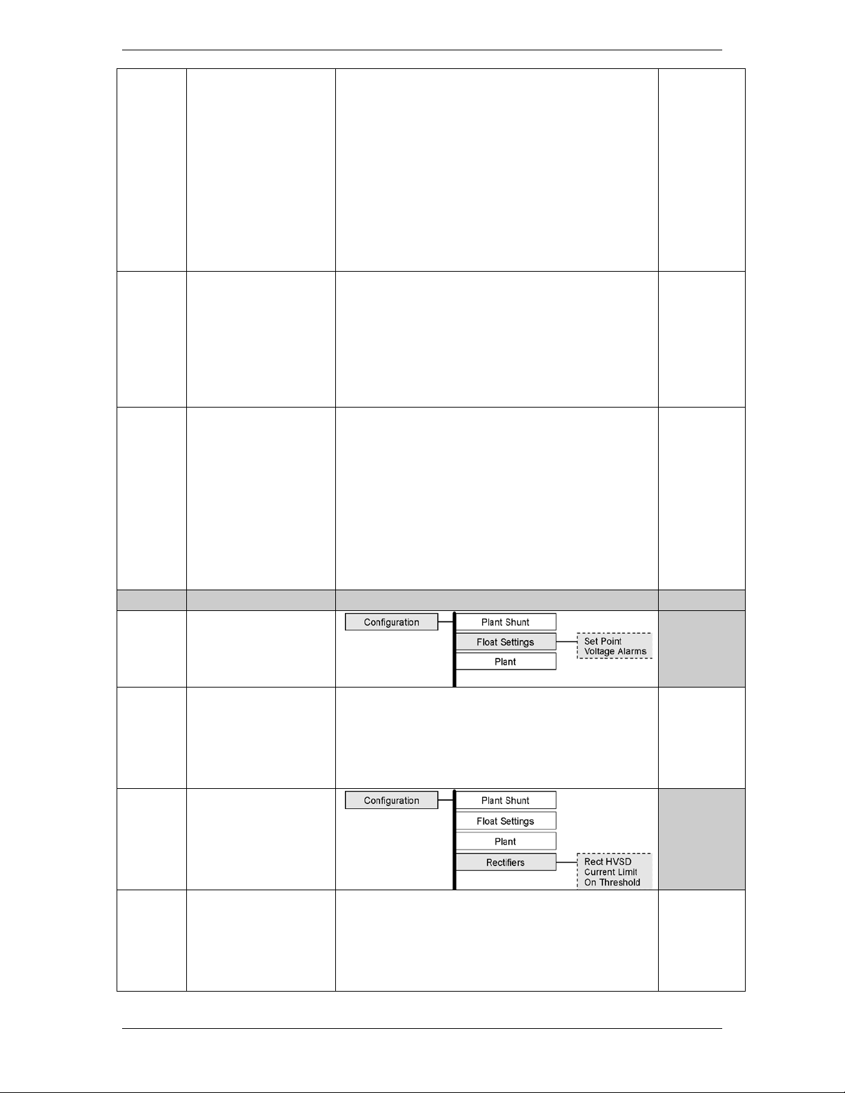
Galaxy Power System GPS2436
plant rather than due to a failure. This alarm
allows the High Voltage (HV) shutdown
to be raised slightly, thus reducing
the number of nuisance shutdowns without
decreasing the plant reliability. Move the
key to adjust the High Voltage shut down
alarm for FLOAT mode to the desired level
ly less than the HV threshold). Press
<ENTER> to save the change.
Battery on
If the plant voltage is less than the threshold
ON, this in turn activates the PMJ and BD
key to adjust the threshold to the desired
Very Low Voltage
This alarm threshold is used to indicate that
the system voltage is very low, and that the
batteries have discharged to a dangerously
low depth. When the plant voltage falls
below this level, the Very Low Voltage (VLV)
and Power Critical alarm will be generated.
<ENTER> to save the change.
5.
Rectifiers
Setpoint
This value sets the system voltage for all
> key to adjust the
threshold value. Press <ENTER> to save the
change.
HVSD
The configuration of this field sets the
internal high voltage shutdown value of all
> key to adjust the
threshold value. Press <ENTER> to save the
threshold
cursor to the fields and use the <+> or <->
(normal
Discharge
value, the Battery Discharge alarm is turned
relay, light the MAJ and BD LEDs. Move the
cursor to the fields, and use the <+> or <->
level. Press <ENTER> to save the change.
Move the cursor to the field and use the <+>
or <-> key to adjust the threshold value. Press
Issue 1 August 2012 70
serial rectifiers. Move the cursor to the field
and use the <+> or <-
serial rectifiers. Move the cursor to the field
and use the <+> or <-
Page 71

Galaxy Power System GPS2436
change.
6.
Batteries
Model
The configuration of this field selects the
defined battery types used in reserve time
prediction and enhanced battery test
features. Move the cursor to the field and
value. Press <ENTER> to save the change.
Strings
The configuration of this field selects the
number of battery strings in the system. This
and enhanced battery test features. Move
key to adjust the threshold value. Press
<ENTER> to save the change.
Cells/String
The configuration of this field selects the
number of installed cells in the battery
strings. This parameter is used in reserve
time prediction and enhanced battery test
features. Move the cursor to the field and
> key to adjust the threshold
value. Press <ENTER> to save the change.
Type
The configuration of this field selects the
(sealed). This parameter is used in reserve
time prediction and enhanced battery test
features. Move the cursor to the field and
> key to adjust the threshold
value. Press <ENTER> to save the change.
7.
Thermal Comp
cell battery voltage as a function of
temperature.
Enabled
Enables or Disables the Thermal
installed battery type from a list of pre-
use the <+> or <-> key to adjust the threshold
parameter is used in reserve time prediction
the cursor to the field and use the <+> or <->
use the <+> or <-
batter type, Flooded or Valve Regulated
use the <+> or <-
Issue 1 August 2012 71
This feature allows dynamic control of sealed
Page 72

Galaxy Power System GPS2436
Compensation Feature. Move the cursor to
to save the
change.
High Temp
Comp
This feature allows the system to
compensate for high temperatures.
Volt Step
Battery step temperature can be set from
185F. At this temperature, the system
voltage is reduced by 0.17 X # of cells/string.
High Comp
Limit
This sets the maximum temperature for
which thermal compensation is active.
Decrease
This sets the slope (mV/degC) for high
temperature compensation.
Nominal
This field set the temperature at which no
The system
voltage is at the setpoint float mode.
Low Temp Comp
This feature allows the system to
compensate for low temperatures.
Low T Comp
This enables or disables the low temperature
compensation feature.
Low Comp
Limit
This sets the minimum temperature for
which thermal compensation is active.
Increase
This sets the slope (mV/degC) for low
temperature compensation.
8.
Recharge Current
This feature sets the total amount of current
Limit
The configuration of this field enables or
disables the feature.
Limit to
This programmable value sets the maximum
amount of recharge current (in Amps) that
will be allowed for recharging the batteries.
The range is from 10 – 1000A.
9.
Contactors
Up to three optional LVD devices can be
connected to a Millennium and configured
the field and use the <+> or <-> key to Enable
or Disable. Press <ENTER>
Limit
Down
Temp
113-
compensation is required.
that will be allowed to recharge the batteries.
Issue 1 August 2012 72
from this screen.
Page 73

Galaxy Power System GPS2436
Contactor 1-3
Type
This setting identifies the type of contactor,
, LOAD or NONE that has been
installed in the plant. Be sure that the wiring
for the contactor being configured matches
the type chosen here. For standard GPS
configurations using BIC cards, Contactor 1 is
and control only LOAD contactors. To toggle
between the various contactor types, move
the cursor to one of the fields and use the
> key to select the desired type.
Press <ENTER> to save the change.
Disconnect
This setting configures the plant voltage at
Reconnect
This setting configures the plant voltage at
BATTERY
wired to and controls all BATTERY contactors
in the plant. Contactors 2 and 3 are wired to
<+> or <-
which the contactor will disconnect from the
bus. Use the <+> or <-> key to adjust the
voltage to the desired level. Press <ENTER>
to save the change.
which the contactor will reconnect to the
bus. To prevent the contactor from reoperating when battery voltage increases
due to load removal, a voltage several volts
higher than the disconnect voltage is
recommended. Use the <+> or <-> key to
adjust the voltage to the desired level. Press
<ENTER> to save the change.
Issue 1 August 2012 73
Page 74

Galaxy Power System GPS2436
Tools and Test Equipment Required for Acceptance Testing
Digital Voltmeter (DVM) with dc accuracy of at least 0.05%
Short length of wire or clip lead for jumper
Jeweler’s screwdriver
Follow these steps to test plant alarms when installing the Galaxy Millennium Controller
in a new plant. In a new installation, begin the sequence with the rectifiers running with
a dummy load on the plant bus bar.
For these tests, it is assumed that:
• All rectifiers are functioning properly.
•
load.
If you are testing a controller in a live plant:
• Some tests will cause a battery discharge. Insure that plant batteries are capable
of supporting the load.
• Alarms will be generated. Notify the appropriate alarm monitoring personnel.
10 Acceptance Testing
Introduction
The Galaxy Millennium Controller is tested before it leaves the factory, but many users
wish to add some test procedures as part of installation and turn-up. The tests
described here will simulate various alarm conditions and verify that the controller
functions properly. Follow the steps listed below in the order they are given.
Tools and Test Equipment
Test Precautions
Plant batteries have received their original charges and are ready to support a
Issue 1 August 2012 74
Page 75

Galaxy Power System GPS2436
This test verifies that All of the LEDs on the front panel of the controller are functioning
Step
Action
1.
From the Default Screen, press the Menu button for the Main Menu.
2.
Using the Up/Down Arrows, Scroll to Control/Operations and press Enter.
3.
Select Start Lamp Test, and press Enter.
4.
Press Enter again to start the test, or Escape to return to the menus.
5.
Observations:
NO alarms are generated from this test
Using a calibrated digital voltmeter, measure the plant voltage from the front panel test
jacks. Follow these steps to calibrate the front panel meter display for Voltage and
Test Sequences
Lamp Test
properly. No alarms are generated from this test.
• LCD Refreshes
• Front Panel LEDs ALL turn on momentarily and return to normal
•
Front Panel Display Meter Calibration
Current readings:
Issue 1 August 2012 75
Page 76

Galaxy Power System GPS2436
Step
Action for Voltage Calibration
1.
Using the Meter Calibration Menus, reset the plant voltage reading by
will remove any pre-existing user calibrated values if they exist.
2.
Wait at least 5 seconds and press the ESCAPE key.
3.
Select CALIBRATE VOLTAGE. Use the Arrows, and UP/DOWN keys to
calibrate the system voltage. Press ENTER to save.
NOTE:
The controller will not allow changes greater than +/- 0.5V of the
displayed voltage.
4.
Press the <ESCAPE> key until the default screen is displayed. Verify that
the plant voltage reading now agrees with the calibrated DVM.
NOTE:
The DVM reading will be the one to change since Rectifier Manager will
adjust rectifier outputs as necessary per the calibration performed.
Step
Action for Current Calibration
NOTE:
The following procedure is applicable only in plants with Load shunts in
a plant configured for “Centralized Architecture.”
1.
Using a calibrated DVM, measure the plant load from the sense
selecting RESET VOLTAGE. Press the Enter key to reset the voltage. This
Issue 1 August 2012 76
Page 77

Galaxy Power System GPS2436
connection points on the plant shunt(s).
2.
Calculate the plant load, in amperes, as measured by the DVM.
This value is the plant load measured by the DVM, in amperes.
3.
Using the Meter Calibration Menus, reset the plant Plant Current
ing RESET LOAD. Press the Enter key to reset the Load.
This will remove any pre-existing user calibrated values if they exist.
4.
Wait at least 5 seconds and press the ESCAPE key.
5.
Select CALIBRATE LOAD. Use the Arrows, and UP/DOWN keys to
calibrate the system Load. Press ENTER to save.
NOTE:
The maximum total change is +/-10% of the cuurent load value.
6.
Press the <ESCAPE> key until the default screen is displayed. Verify that
the plant current reading has been changed.
NOTE:
This operation is performed and verified ONLY if plant load is constant
during the calibration procedure.
Observation:
• Displayed System load changes to new value.
Step
Action for Testing the High Float Voltage Alarm
NOTE:
Clear all controller alarms for this test.
NOTE:
The high voltage alarm test is completed by raising the plant voltage
above the threshold set for HFV (High Float Voltage) .
NOTE:
Raising the plant voltage on a working system is left to the discretion of
If the test is performed, verify that the plant is in FLOAT
Rectifier voltage has been set to the normal level after
completing the test.
1.
Using the Voltage Alarms Menu Screens, note High Float Alarm
threshold value. _________
2.
Using the Float Settings Menu Screens, select Set Point and note the
value. ________
NOTE:
The next step WILL RAISE the system voltage.
3.
Use the Arrows, and UP/DOWN keys to change the system float voltage
setpoint to 0.1V above the High Float Alarm Threshold.. Press ENTER to
save.
4.
Observe:
• RECT and MIN LEDs are illuminated
a) Divide the mV DVM reading by the rated shunt mV value
b) Multiply this result by the shunt ampere rating
reading by select
High Float Voltage Alarm – New Installations
the user.
• This test could disrupt power to working equipment.
•
mode
•
Issue 1 August 2012 77
• Power Minor alarm (PMN) is generated
• The plant voltage increases to the set voltage
Page 78

Galaxy Power System GPS2436
5.
Using the Float Settings Menu Screens, select Set Point.
6.
Use the Arrows, and UP/DOWN keys to change the system float voltage
setpoint to it’s original value. Press ENTER to save.
7.
Observe:
RECT and MIN LEDs are extinguished
Step
Action for Testing the High Float Voltage Alarm
NOTE:
Clear all controller alarms for this test.
NOTE:
The System Voltage WILL NOT change.
NOTE:
The high float voltage alarm test is completed by changing the threshold
for this condition below the system voltage to make it active.
1.
Using the Float Settings Menu Screens, select Set Point and note the
value. ________
2.
Using the Voltage Alarms Menu Screens, note the High Float Alarm
threshold value. _________
3.
Use the Arrows, and UP/DOWN keys to change the High Float Alarm
Threshold to 0.1V below the System Voltage. Press ENTER to save.
4.
Observe:
RECT and MIN LEDs are illuminated
5.
Using the Voltage Alarms Menu Screens, change the High Float Alarm
threshold value to it’s original value. Press ENTER to save.
6.
Observe:
RECT and MIN LEDs are extinguished
STEP
Action for Testing High Voltage Shutdown Alarm
NOTE:
The High Voltage Shutdown Test is recommended only for new
office load, and batteries are connected.
NOTE:
There are three requirements for a serial rectifier to shut down upon a
The plant voltage must be above the level set for the High
The rectifier must be delivering a current of at least 10% of its
capacity.
• The plant voltage decreases to the original set voltage
• Power Minor alarm (PMN) retires
•
High Float Voltage Alarm – Systems with Actual Loads
• Power Minor alarm (PMN) is generated
•
• Power Minor alarm (PMN) retires
•
High Voltage Shutdown – New Installations Only
installations where a dummy load is available prior to the application of
controller initiated High Voltage Alarm.
1.
Voltage alarm at the VOLTAGE ALARMS menu screen:
MENUCONFIGUREFLOAT SETTINGSVOLTAGE ALARMS
2.
Issue 1 August 2012 78
Page 79

Galaxy Power System GPS2436
3. The rectifier’s current output must be unbalanced by more than
Because item 3 is difficult to achieve in a simulation test of properly
functioning serial rectifiers, (even with load share disabled), rectifiers
are tested one at a time, rather than as a group. Slightly different test
rectifiers have their own internal restart circuits which will function 3
times before the rectifier locks itself out and initiates a High Output
ficient interval
between restart and a subsequent shutdown the rectifier resets its
restart counter. The controller initiates a restart signal a few seconds
first RFA (HO) alarm is received. After the second RFA (HO) is received,
aits 5 minutes before sending one additional restart
1.
Verify the Auto Restart is enabled from the front panel menus:
2.
Turn off all rectifiers except the rectifier under test by operating their
power switches to STBY.
3.
Adjust the dummy load to provide 10 to 30% of the rectifier’s output
capacity.
4.
Using the Voltage Alarms Menu Screens, note High Voltage Alarm
threshold value. _________
5.
Using the Float Settings Menu Screens, select Set Point and note the
value. ________
NOTE:
The next step WILL RAISE the system voltage.
6.
Use the Arrows, and UP/DOWN keys to change the system float voltage
to save.
7.
Controller Observations:
When the voltage increases to the HV (FLOAT) level the
• After 5-6 seconds the rectifier initiates its own restart
10% from the average output currents of the other rectifiers.
procedures are used for special applications in batteryless plants. Serial
Rectifier Fail Alarm to the controller. If there is a suf
after the
the controller w
signal.
setpoint to 0.1V above the High Voltage Alarm Threshold.. Press ENTER
• The plant voltage increases
• Power Major alarm (PMJ) is generated
• RECT and MAJ LEDs are illuminated
Rectifier Observations:
•
rectifier shuts down.
• The Green ON LED on the rectifier blinks, the ALM LED on
the rectifier is not lit.
Issue 1 August 2012 79
Page 80

Galaxy Power System GPS2436
signal again raising the plant voltage.
The rectifier will shutdown and restart two additional
Upon the third shutdown, the rectifier’s ALM LED lights
ON LED on the
Upon the fourth shutdown, the rectifiers ALM LED lights
s and issue one final
restart signal initiating the final sequence of shutdown
and restart events before the rectifier locks out, requiring
Prior to this occurring, change the value of the
Restart the rectifier from the front panel by using
8.
Using the Float Settings Menu Screens, select Set Point.
9.
Use the Arrows, and UP/DOWN keys to change the system float voltage
This value must be at least 0.5V below the HV alarm threshold setting.
Press ENTER to save.
10.
Controller Observations:
• Rectifier is operating normally
•
times.
•
and the rectifier’s display indicates “HO”.
• The controller receives the RFA signal from the rectifier
and initiates a restart signal 5-6 seconds later.
• The rectifier restarts again raising plant voltage.
• The rectifier shuts down and restarts 3 additional times.
• During these shutdowns the Green
rectifier blinks and the ALM LED on the rectifier is not lit.
•
and the rectifier’s display indicates “HO”.
• Any external RFA office alarm has occurred.
• The controller will wait 5-6 minute
personnel intervention.
o
system voltage to its original value. Press ENTER
to save the change.
o
the menus:
setpoint to its original value
• The plant voltage returns to it’s original value
• Power Major alarm (PMJ) retires
• RECT and MAJ LEDs are extinguished
Rectifier Observations:
Issue 1 August 2012 80
Page 81

Galaxy Power System GPS2436
STEP
Action for Testing the Battery on Discharge Alarm
NOTE:
If the BD alarm was observed during the High Voltage Shutdown test
this test can be disregarded.
1.
From the front panel follow the path(Voltage Alarms):
2.
Note the setting of the Battery on Discharge Threshold. ________
3.
With a dummy load added to the plant, operate all rectifiers to STBY
until the plant voltage drops below the BD (FLOAT) threshold.
4.
Controller Observations:
BD and MAJ LEDs are illuminated
5.
Turn on all rectifiers
6.
Controller Observations:
System Voltage is normal
The RFA alarm was observed during the High Voltage Shutdown Test so no separate test
is required.
Major Fuse Alarm may be tested by placing a blown fuse in the alarm fuse position of
indicating hole of its fuse holder.
For distribution circuit breakers, temporarily connect the pins 8 and 9 of any KS22010
BNL1 alarm board.
Observation:
• Remove alarm condition and verify that DIST,MAJ LEDs and MJF relay retire.
Alarms should be tested in each distribution bay of the plant to verify the integrity of
the alarm bus throughout the plant.
If the distribution bays are equipped with “Bay Fuse Alarm” indicating LEDs, also verify
not in any other).
Battery on Discharge Alarm
• PMJ Alarm is active
•
• PMJ Alarm retires
• BD and MAJ LEDs are extinguished
•
Rectifier Fail Alarm
Major Fuse Alarm
any distribution fuse position in the plant or by inserting a paper clip into the alarm
or KS22012 style circuit breakers together. This is accomplished on the ED83143-30
circuit breaker panels by shorting the (-) panel bus to pin 1 on the P4 connector of its
• The DIST and MAJ LEDs and Power Major and MJF alarm relays will be active.
that this LED activates during these tests for the bay in which the alarm originates (and
.
Issue 1 August 2012 81
Page 82

Galaxy Power System GPS2436
This feature is useful when there is a need to remove unnecessary historical data from
operation. There may be history that is of no use to the customer. Also, since
the history log has a finite number of entries, user can save the history using a PC, and
Step
Action
1.
From the Default Screen, press the Menu button for the Main Menu.
2.
Using the Up/Down Arrows, Scroll to Control/Operations and press Enter.
3.
Select Clear History, and press Enter.
4.
Press Enter again to clear the History Log, or Escape to return to the menus.
Clear History
the controller. An example might be after installation and testing and the controller is
ready for
then clear the logs.
Issue 1 August 2012 82
Page 83

Galaxy Power System GPS2436
it is used to calculate current. Terminal boards located on the battery connection
11 Circuit Boards
Overview
Function
Circuit boards (sometimes referred to as “cards”) are included in the battery
connection and dc distribution panels to provide data to the controller.
Terminal Boards
Terminal boards are used to provide shunt voltage data to the controller, where
panels provide data that is used to calculate battery current; data from terminal
boards located on the dc distribution panels is used to calculate load current.
Alarm Boards
Alarm boards perform two functions:
• monitor panel functions and activate local indicators when faults occur on
the panel
• provide alarm data to the controller
Alarm/Terminal Boards
Alarm/terminal boards combine the functions of alarm boards and terminal
boards.
BLJ Terminal Board
The BLJ terminal board is located inside the cabinet door. The BLJ is the
termination point for all signal cables in each cabinet and between cabinets.
Issue 1 August 2012 83
Page 84

Galaxy Power System GPS2436
Overview, continued
based on maintenance switch
Contactor Control Board (installed only on systems with contactors)
Contactor control boards provide four functions:
• Monitor and report shunt voltage to the controller
• Monitor and report contactor status to the controller
• Operate the contactor based on controller commands
• Operate or block the contactor from operating
settings
Bay Interface Card (BIC)
Every cabinet in a Galaxy Power System has a Bay Interface Card (BIC). The BIC
provides controller access to alarm monitoring, battery voltages, battery
currents, and temperature probes in the cabinet through the serial rectifier bus.
Issue 1 August 2012 84
Page 85

Galaxy Power System GPS2436
Galaxy Power System 2436 Specifications
Electrical
AC Input
• 50A circuit breaker per rectifier for individual feeds
• 8 gauge/10 mm
- per rectifier for individual feeds
Cabinet Output +24V
System Output +24V
2 x Full Height
Maxi mum System
1. With Galaxy Millennium Controller
12 Specifications
GPS2436
Input Distribution
NE100AC24ATEZ
Minimum Wire Size
NE100AC24ATEZ
Output Current
NE100AC24ATEZ 100 - 2000A
• 125A circuit breaker per 2-shelf cabinet
• 150A circuit breaker per 3-shelf cabinet
• 25A circuit breaker per rectifier for individual feeds
• 110 / 125A circuit breaker per 1-shelf cabinet
• 2 x 110 / 125A circuit breaker per 2-shelf cabinet
• 2 x 150A circuit breaker per 3-shelf cabinet
• 2 gauge/35 mm
• 1/0 gauge/50 mm
• 10 gauge/6 mm
• 2 gauge/35 mm
• 2 x 2 gauge/35 mm
• 2 x 1/0 gauge/50 mm
2
- 1 and 2-shelf cabinet
2
- 3-shelf cabinet
2
- per rectifier for individual feeds
2
- 1-shelf cabinet
2
- 2-shelf cabinet
2
- 3-shelf cabinet
2
Output Current
NE100AC24ATEZ
100 - 2000A
Issue 1 August 2012 85
2000A
Page 86

Galaxy Power System GPS2436
Galaxy Power System 2436 Specifications (continued)
Mechanical
Cabinet
Full Height
(82.6 H x 23.6 W x 23.6 D in.)
Units Per Initial Cabinet
Full Height
Rectifiers
1 - 36
Controller
1
Battery Disconnect Modules
0 - 1
installed in other cabinets.
Units Per Supplementa l C abinet
Rectifiers
1 - 36
Battery Disconnect Modules
0 - 1
installed in other cabinets.
Environmental
Altitude
-50 to 4000 meters
temperature by 0.656°C per 100 meters.
Humidity
5% to 95% non-condensing
Radiated and Conducted
EN50082-1, EN50082-2, EN50081, EN61000
Electromagnetic Immunity
Level B
Earthquake Rating
Zone 4, upper floors
Standards Compliance
Agency Appro va ls
CE Marked, UL
Nominal Cabinet Dimensions
(H x W x D)
DC Distribution Maximum discharge is 1600 amps per cabinet. No distribution panels can be
DC Distribution Maximum discharge is 1600 amps per cabinet. No distribution panels can be
Operating Ambient
Temperature
NE100AC24ATEZ
2100 H x 600 W x 600 D mm
installed in a rectifier only cabinet, as many distribution panels as will fit can b e
installed in a rectifier only cabinet, as many distribution panels as will fit can b e
-40°C to +75°C
Note: For altitudes between 1500 and 4000 meters, derate the maximum
Emissions
Underwriters Laboratories (UL) Listed per Subject Letter 1801, DC Power
Distribution Centers for T e le communic a tions Equipment
Issue 1 August 2012 86
Page 87

Galaxy Power System GPS2436
Rectifier Specifications
Electrical
Input
(150 Vac - 300 Vac with reduced performance)
Frequency Range
45 - 66 Hz
Power Factor
> 0.98 at > 50% rated output
810Vpeak 100A peak (8 x 20s)
Output All
Float:
Boost:
Equalize:
Float/Boost:
Equalize:
1. Selectable/programmable through Galaxy Controller
2.
3.
Output NE100AC24ATEZ
1 ampere per degree C (+65°C to +85°C)
Float/Boost Voltage
21-29Vdc
Total Harmonic Distortion
<5% at full load
Regulation
±0.5%
Ripple
100 mVrms
Noise
< 2mV psophometric
Rectifier
850022020 GPS2436 Prod Man r01.docx
Voltage Range 175-275Vac, 2-wire, single phase
AC Surge Protection: It is important that ac surges reaching rectifiers do not exceed the capacity of the
rectifier internal surge protection. Protection must be provided external to the GPS system, if necessary,
to limit surge energy reaching the rectifiers. Site surge protection must be coordinated with rectifier
internal surge protection and must clamp at a lower voltage than the rectifier internal protection. The
internal protection voltage and current characteristics of the rectifiers are as follows:
Phase to Phase Voltage MOV Conduction Current
320Vac (RMS) 0A
620V maximum clamping 1mA (DC test current)
High Voltage Shutdown
Internal Selective High Voltage Shutdown
(ISHVSD)
Backup High Voltage Shutdown (BUHVSD)
Factory default settings – actual range is 44 - 60Vdc
Factory default settings – Float/Boost range is 58.51 - 60.53Vdc,
Equalize range is 65.2 - 67.0Vdc
Output Power1 3,000W maximum
Output Current1 55Adc maximum from -40°C to +65°C
Issue 1 August 2012 87
56.0Vdc Nom.1,
56.0Vdc Nom.1,
2
2
59.52 ± 1Vdc Nom.1,
59.52Vdc
3
66.0Vdc3
42.5Adc at +75°C
30Adc at +85°C
Rectifier derates at approximately
2
Page 88

Galaxy Power System GPS2436
Current Limit Set Point
15A-55A
Issue 1 August 2012 88
Page 89

Galaxy Power System GPS2436
Output NE100AC24ATEZ (Continued)
1, 2
1, 2
2.5 amperes per degree C (+60°C to +75°C)
Float/Boost Voltage
42-58Vdc
Total Harmonic Distortion
<5% at Nominal Vac and >50Adc
Regulation
±0.5%
Ripple
100 mVrms
Noise
< 2mV psophometric
Current Limit Set Point
30A-110A
Mechanical
Width
5.25 in. (133.35 mm)
Height
8 in. (203.2 mm)
Depth
19.75 in. (501.65 mm)
Weight
20 lbs. (9 kg)
Environmental
Efficiency
> 90% typical
Heat Release
54.5Vdc, 110A
Per rectifier:
666W [2,266 BTU/hr]
Storage Relative Humidity
5% to 90%
Audible Noise
< 52dBA
EMC
EN 50022, level B, conducted and radiated (CISPR 22)
Standards Compliance
Safety Standard
EN 60950 (IEC950)
Body and have outputs classified as SELV.
Output Power
Output Current
6,000W maximum
110Adc maximum from -40°C to +45°C
85Adc at +60°C
60Adc at +70°C
47.5Adc at +75°C
Rectifier self-derates at approximately
1.5 amperes per degree C (+45°C to +60°C)
NE100AC24ATEZ 52Vdc, 40A
52Vdc, 50A
54.5Vdc, 40A
54.5Vdc, 50A
55Vdc, 55A
NE100AC24ATEZTEZ 52Vdc, 80A
52Vdc, 100A
54.5Vdc, 80A
54.5Vdc, 100A
Certification Marks UL, VDE, CE
231W [788.9 BTU/hr]
288W [983 BTU/hr]
242W [827 BTU/hr]
302W [1,030 BTU/hr]
332W [1,133 BTU/hr]
463W [1,578 BTU/hr]
577W [1,966 BTU/hr]
485W [1,654 BTU/hr]
605W [2,060 BTU/hr]
Rectifiers are individually UL Recognized and/or CSA
Certified to UL1950 and CSA C22.2 No 234/950. Rectifiers
are also approved to IEC-950/EN60950 by an EC Notified
Issue 1 August 2012 89
Page 90

Galaxy Power System GPS2436
13 Safety
Please read and follow all safety instructions and warnings before servicing the GPS2436.
Reference the GPS Installation Guide for safety statements specific to the modules.
Safety Statements
Please read and follow all safety instructions and warnings before installing,
maintaining, or repairing the system:
• The CE Mark demonstrates compliance with the European Union Council
Directives for Low Voltage and EMC.
• The UACD is Underwriters Laboratories (UL) recognized per Subject Letter 1801,
DC Power Distribution Centers for Telecommunications Equipment.
• Install only in restricted access areas (dedicated equipment rooms, equipment
closets, or the like) in accordance with articles 110-26, 110-27, and 110-18 of the
U.S. National Electric Code (NEC-2011), ANSI/NFPA No. 70, and pursuant to
applicable local codes.
• This equipment is to be used in controlled environments (an area where the
humidity is maintained at levels that cannot cause condensation on the
equipment, the contaminating dust is controlled, and the steady-state ambient
temperature is within the range specified).
• This equipment has been evaluated for continuous use in ambient temperature
from 5°C to 55°C.
• This equipment must not be installed over combustible surfaces.
• For installations in the United States, Listed compression connectors are to be
used to terminate Listed field-wired conductors where required. For all
installations, the appropriate connector is to be applied only to the correct size
conductor as specified by the connector manufacturer, using only the connector
manufacturer’s recommended tooling or tooling approved for that connector.
• The shelf in combination with the EP300048ATEZ has not been evaluated for hot-
swapping.
• If the proper connector for the country of installation is not provided, obtain
appropriate connectors and follow manufacturers and all local requirements for
proper connections. All national and local rules and regulations should be
followed when making field connections.
Issue 1 August 2012 90
Page 91

Galaxy Power System GPS2436
• All input and output connections comply with SELV requirements.
• Insulation on field-wired conductors should be rated no less than 90° Celsius. Size
conductors based on listed recommendations. Wiring internal to enclosed
equipment cabinets should be rated at 105° Celsius (minimum).
• Torque or secure electrical connections to the values specified on labels or in the
product documentation.
• Alarm contacts on the office alarm connector are not fused within the controller;
therefore, current limiting protection for these contacts must be provided by
external circuits. Maximum ratings for alarm connections are 60Vdc and 0.5
amperes. Exceeding these maximum ratings could result in fire or damage to the
unit.
• In enclosed equipment cabinets, the chassis must be connected directly to the
cabinet ac service ground bus. For applications in huts, vaults, and central offices,
the chassis must be connected to the system integrated ground grid.
• This product operates equally well if installed as part of the Isolated Ground
Plane (Isolated Bonding Network) or the Integrated Ground Plane (MeshBonding Network, aka, Common Bonding Network). Lineage recognizes there are
different grounding techniques that are equally successful. Adhere to a
commonly accepted and consistent grounding approach to ensure personnel
safety, network protection, and proper equipment operation. Multiple low
impedance paths to Earth ground are essential.
• The equipment and subassembly ports are suitable for connection to intra-
building or unexposed wiring or cabling. The equipment and subassembly ports
can be connected to shielded intra-building cabling grounded at both ends.
Issue 1 August 2012 91
Page 92

Galaxy Power System GPS2436
14 Maintenance and Replacement
Requirements
System
With the exception of the batteries, periodic maintenance specific to the power system is not
required. The ac service for the building must be maintained with ANSI specified limits. The
temperature and humidity within the power room must be maintained within the limits
specified in this product manual.
Batteries
The batteries must be maintained as directed by the battery manufacturer’s requirements.
Rectifiers
Rectifiers are repaired by replacement. Refer to “Installing or Replacing a Rectifier” in this
section.
Rectifier Fans
Rectifier fans are not field replaceable. See the Customer Service Contacts section of this manual
for return information.
Issue 1 August 2012 92
Page 93

Galaxy Power System GPS2436
Step
Action
1
to the rectifier position that is being installed or replaced.
Caution
the rectifier.
Slide the rectifier into the slot until it engages with the rear
Verify the faceplate is latched.
Rectifier Installation and Replacement Procedures
Installing or Replacing a Rectifier
Installing or Replacing a Rectifier
Locate and turn off the ac service to the rectifier position
that is being installed or replaced.
Note: Do not turn off ac service to the entire system, only
2
Rear portion of the rectifier that is in operation may be
HOT to the touch. Use appropriate precautions.
(This step is for replacement only. For a new installation,
3
proceed to the next step).
Open the faceplate by sliding the faceplate latch to the left
until the faceplate releases and swings outward. Remove
Remove rectifier from its shipping package. Slide the
4
rectifier into the slot approximately ¾ of the way.
Open the faceplate by sliding the faceplate latch to the left
5
until the faceplate releases and swings outward.
6
of the shelf. Swing the faceplate closed to seat the rectifier.
Issue 1 August 2012 93
Page 94

Galaxy Power System GPS2436
Table 1: Warnings
15 Troubleshooting Procedure
Preliminary
Introduction
This section provides information needed in preparation for locating and interpreting visual
indicators to help identify problems.
When replacing a part does not correct the problem or visual indicators do not identify a
defective part, notify Lineage Power Technical Support.
Safety
Review all safety instructions and warnings in the Safety section of the GPS Installation Guide
before troubleshooting the GPS2436.
• Hazardous ac and dc voltages and/or energy are present.
Caution should be exercised. Tools must be insulated to help
prevent accidental contact with live surfaces.
• Coordinate all troubleshooting activities with other personnel
that may be working on the system.
Tools
The following tools are necessary in order to troubleshoot the GPS2436:
• Calibrated digital voltmeter (DVM)
(0.05% accuracy on dc scale)
• ESD wrist strap
Issue 1 August 2012 94
Page 95

Galaxy Power System GPS2436
Figure 12-1: Location of cabinet alarm indicators
Troubleshooting Procedure
Purpose
The troubleshooting procedure described below is used when a trouble condition has
been identified and a technician has been dispatched to the system as a first step in
diagnosing and correcting the problem.
For all trouble conditions, proceed as follows:
Cabinet Alarm
1. Locate the Galaxy controller. When a trouble condition exists, the red alarm on the
top of the cabinet will be illuminated and the display screen on the controller will
typically have LED’s illuminated. See Figure 12-1.
2. Determine the system status. For most problems, one or more alarm and status
LEDs will be illuminated. Depending on the controller type, the following will be
displayed:
– system voltage
– system current
– system mode
– system number of alarm/warnings
If the screen is blank, but alarm and status LEDs are illuminated, call technical
support.
If the entire panel is blank, check the controller fuses. Verify that the controller is
getting power. If not, replace fuse. If the display is still blank, call technical support.
3. To view the Alarms Menu: If the default screen appears normal, press the MENU
button. The main menu appears with “Alarms” blinking. Press ENTER to obtain the
Alarms menu. Additional data appears that will help to identify the problem.
Issue 1 August 2012 95
Page 96

Galaxy Power System GPS2436
Table 1: Warranty Period
Product Type
New Product
Repaired Product*
Power Equipment
*The Warranty Period for a repaired Product or part thereof is six (6) months
16 Product Warranty
A. Seller warrants to Customer only, that:
1. As of the date title to Products passes, Seller will have the right to sell, transfer, and assign such
Products and the title conveyed by Seller shall be good;
2. During the warranty period stated in Sub-Article B below, Seller’s Manufactured Products
(products manufactured by Seller), which have been paid for by Customer, will conform to
industry standards and Seller’s specifications and shall be free from material defects;
3. With respect to Vendor items (items not manufactured by Seller), Seller warrants that such
Vendor items, which have been paid for by Customer, will be free from material defects for a
period of sixty (60) days commencing from the date of shipment from Seller’s facility.
B. The Warranty Period listed below is applicable to Seller’s Manufactured Products furnished pursuant
to this Agreement, commencing from date of shipment from Seller’s facility, unless otherwise agreed
to in writing:
Central Office
or, the remainder of the unexpired term of the new Product Warranty
Period, whichever is longer.
C. If, under normal and proper use during the applicable Warranty Period, a defect or nonconformity is
identified in a Product and Customer notifies Seller in writing of such defect or nonconformity
promptly after Customer discovers such defect or nonconformity, and follows Seller's instructions
regarding return of defective or nonconforming Products, Seller shall, at its option attempt first to
repair or replace such Product without charge at its facility or, if not feasible, provide a refund or
credit based on the original purchase price and installation charges if installed by Seller. Where Seller
has elected to repair a Seller’s Manufactured Product (other than Cable and Wire Products) which has
been installed by Seller and Seller ascertains that the Product is not readily returnable for repair,
Seller will repair the Product at Customer’s site.
With respect to Cable and Wire Products manufactured by Seller which Seller elects to repair but
which are not readily returnable for repair, whether or not installed by Seller, Seller at its option, may
repair the cable and Wire Products at Customer’s site.
D. If Seller has elected to repair or replace a defective Product, Customer shall have the option of
removing and reinstalling or having Seller remove and reinstall the defective or nonconforming
Product. The cost of the removal and the reinstallation shall be borne by Customer. With respect to
Cable and Wire Products, Customer has the further responsibility, at its expense, to make the Cable
and Wire Products accessible for repair or replacement and to restore the site. Products returned for
repair or replacement will be accepted by Seller only in accordance with its instructions and
procedures for such returns. The transportation expense associated with returning such Product to
Seller shall be borne by Customer. Seller shall pay the cost of transportation of the repaired or
replacing Product to the destination designated by Customer.
24 Months 6 Months
Issue 1 August 2012 96
Page 97

Galaxy Power System GPS2436
E. Except for batteries, the defective or nonconforming Products or parts which are replaced shall
become Seller's property. Customer shall be solely responsible for the disposition of any batteries.
F. If Seller determines that a Product for which warranty service is claimed is not defective or
nonconforming, Customer shall pay Seller all costs of handling, inspecting, testing, and transportation
and, if applicable, traveling and related expenses.
G. Seller makes no warranty with respect to defective conditions or nonconformities resulting from
actions of anyone other than Seller or its subcontractors, caused by any of the following:
modifications, misuse, neglect, accident, or abuse; improper wiring, repairing, splicing, alteration,
installation, storage, or maintenance; use in a manner not in accordance with Seller’s or Vendor’s
specifications or operating instructions, or failure of Customer to apply previously applicable Seller
modifications and corrections. In addition, Seller makes no warranty with respect to Products which
have had their serial numbers or month and year of manufacture removed, altered, or experimental
products or prototypes or with respect to expendable items, including, without limitation, fuses, light
bulbs, motor brushes, and the like. Seller’s warranty does not extend to any system into which the
Product is incorporated. This warranty applies to Customer only and may not be assigned or extended
by Customer to any of its customers or other users of the Product.
THE FOREGOING WARRANTIES ARE EXCLUSIVE AND ARE IN LIEU OF ALL OTHER EXPRESS AND IMPLIED
WARRANTIES, INCLUDING BUT NOT LIMITED TO WARRANTIES OF MERCHANTABILITY AND FITNESS FOR A
PARTICULAR PURPOSE. CUSTOMER’S SOLE AND EXCLUSIVE REMEDY SHALL BE SELLER’S OBLIGATION TO
REPAIR, REPLACE, CREDIT, OR REFUND AS SET FORTH ABOVE IN THIS WARRANTY.
Issue 1 August 2012 97
 Loading...