

Page 1

Galaxy Power System
Verification Procedures
User’s Guide
Select Code 167-792-010
Comcode 108639659
Issue 3
January 2008
Page 2

Page 3

User’s Guide
Select Code 167-792-010
Comcode 108639659
Issue 3
January 2008
Galaxy Power System
Verification Procedures
Notice:
The information, specifications, and procedures in this manual are
subject to change without notice. Lineage Power assumes no
responsibility for any errors that may appear in this document.
© 2008 Lineage Power
All International Rights Reserved
Printed in U.S.A.
Page 4

Page 5

Galaxy Power System Verification Procedures
Table of Contents
1 Introduction
2 Galaxy SC Controller Performance
Verification Procedures
Introduction 2 - 1
Tools 2 - 1
Precautions 2 - 1
Illustrations 2 - 2
Lamp Test 2 - 6
Alarm Test 2 - 6
Local Alarm Test 2 - 6
Remote Alarm Test 2 - 8
High Float Voltage Alarm/High Voltage Shutdown Alarm Tests 2 - 9
Overview 2 - 9
Preparations 2 - 9
HV/HVSD Test Procedure for Parallel Rectifiers 2 - 10
HFV Test Procedure for Serial Rectifiers 2 - 11
HVSD Test Procedure for Serial Rectifiers 2 - 12
Battery on Discharge Alarm Test 2 - 16
Rectifier Fail Alarm Test 2 - 17
Lucent Serial Rectifiers 595 and 596 Series 2 - 17
J855- or J874-Series Rectifiers 2 - 17
150A SMR Rectifiers 2 - 18
50A SMR Rectifiers 2 - 19
Terminate Rectifier (TR) Test 2 - 20
Fuse Alarm Test 2 - 21
Major Fuse Alarm 2 - 21
Minor Fuse Alarm 2 - 21
Modem/Data Switch 2 - 22
Remote Peripheral Monitoring 2 - 22
Rectifier Sequencing 2 - 22
Energy Management 2 - 23
Meter Calibration from the Front Panel 2 - 25
Voltage Calibration 2 - 25
Current Calibration 2 - 26
Battery Discharge Test 2 - 27
Issue 3 January 2008 Table of Contents - 1
Page 6

Galaxy Power System Verification Procedures
3 Galaxy Millennium Controller Performance
Verification Procedures
Introduction 3 - 1
Tools 3 - 1
Precautions 3 - 1
Lamp Test 3 - 2
Alarm Test 3 - 2
Local Alarm Test 3 - 3
Remote Alarm Test 3 - 5
High Float Voltage Alarm Test 3 - 6
Introduction 3 - 6
Preparations 3 - 6
Testing High Float Voltage Alarms 3 - 6
High Voltage Shutdown Test 3 - 7
Overview 3 - 7
Serial Rectifiers 3 - 8
Battery Plant HVSD Test 3 - 9
Battery on Discharge Alarm Test 3 - 12
Rectifier Fail Alarm Test 3 - 12
Terminate Rectifier (TR) Test 3 - 13
Fuse Alarm Test 3 - 14
Introduction 3 - 14
Major Fuse Alarm (FAJ) 3 - 14
Minor Fuse Alarm (FAN) 3 - 14
Modem/Data Switch 3 - 15
Remote Peripheral Monitoring 3 - 15
Rectifier Sequencing 3 - 15
Energy Management 3 - 16
Meter Calibration from the Front Panel 3 - 17
Voltage Calibration 3 - 17
Current Calibration 3 - 18
Battery Discharge Test 3 - 19
Discharge Menu 3 - 20
Procedure 3 - 22
Test Completion 3 - 23
4 Replacement Procedures
Overview 4 - 1
Memory Backup Battery Replacement for SC/SCF Controller 4 - 2
Backup System Configuration 4 - 2
Replace Memory Backup Battery 4 - 3
Restore System Configuration 4 - 4
Memory Backup Battery Replacement for Millennium Controller 4 - 5
Backup System Configuration 4 - 5
2 - Table of Contents Issue 3 January 2008
Page 7

Galaxy Power System Verification Procedures
Backup System Configuration 4 - 6
Replace Memory Backup Battery 4 - 7
Restore System Configuration 4 - 7
Requirements 4 - 8
System 4 - 8
Batteries 4 - 8
Rectifiers 4 - 8
Rectifier Fan Assembly 4 - 8
Converters 4 - 9
GPS2424 Replacement Procedures 4 - 10
Installing or Replacing a 596B3 Rectifier 4 - 10
Replacing a 596B3 Rectifier Fan Assembly 4 - 12
Replacing a 597A or 597B Converter Carrier 4 - 13
Replacing a 47A Converter Module 4 - 14
Replacing a 128A Converter Interface Card 4 - 14
Replacing a Converter Fan Assembly 4 - 15
GPS4812 Replacement Procedures 4 - 16
Installing or Replacing a 596A Rectifier 4 - 16
Replacing a 596A Rectifier Fan Assembly 4 - 17
GPS4848 Replacement Procedures 4 - 18
Installing or Replacing a 595A or 595B Rectifier 4 - 18
Removing a Rectifier 4 - 21
Replacing a 595A or 595B Rectifier Fan Assembly 4 - 22
Testing 4 - 24
Testing Additional Alarms After Replacing Rectifiers 4 - 24
Testing Rectifiers and Load Share in Bay Expansions 4 - 24
5 Glossary
SC Controller Circuit Boards 5 - 2
SCF Controller Circuit Boards 5 - 4
Millennium Controller Circuit Boards 5 - 8
Issue 3 January 2008 Table of Contents - 3
Page 8

Page 9

Galaxy Power System Verification Procedures
List of Figures
Figure 2-1: Location of Galaxy SC Controller Circuit Boards 2 - 2
Figure 2-2: TB2 and TB3 of Galaxy SC Controller 2 - 3
Figure 2-3: Location of Galaxy SCF Controller Circuit Boards 2 - 4
Figure 2-4: TB2 and TB3 of Galaxy SCF Controller 2 - 5
Figure 3-1: Galaxy Millennium Controller Switch Positions 3 - 2
Figure 4-1: Detail of 596B3 Rectifier Position 4 - 10
Figure 4-2: Detail of Converter Components 4 - 13
Figure 4-3: Cable Connection Between Two Converter
Carriers 4 - 13
Figure 4-4: Detail of 596A Rectifier Position 4 - 16
Figure 4-5: Installing a Rectifier in a Rectifier Shelf 4 - 19
Figure 4-6: Replacing a Rectifier Fan Assembly 4 - 22
Issue 3 January 2008 List of Figures - 1
Page 10

Page 11

Galaxy Power System Verification Procedures
1 Introduction
Overview This manual provides general verification procedures for inspection and
testing of Lineage Power Galaxy Power System (GPS) products. The
test procedures mentioned in this manual correspond to controller
software version 6.5.
The Lucent GPS family of products is designed to operate
maintenance-free, without the need for any regular adjustments or fine
tuning. The output voltage and current limit are set by the controller, and
the information is sent as a broadcast message to all rectifiers. All the
rectifier outputs will be automatically adjusted to this level; no
individual rectifier level voltage adjustment is required.
If, however, the customer requires any kind of routine verification or
inspection (even though Lineage Power does not recommend it), the
techniques described in this manual may be used as guidelines to test all
the alarms.
The tests described here will simulate various alarm conditions and
verify that the controller functions properly.
The fans used in the 595-Series and 596-Series rectifiers have a typical
lifetime of 7 years. The fans in the 597A and 597B 24V/48V converter
carriers have a typical lifetime of 4 to 5 years. Lucent recommends that
these fans be replaced at these intervals as described in Section 4,
Replacement Procedures in this manual.
Note: Fan assemblies should be kept dust-free at all times. Air flow
through the rectifiers is important for the proper operation of the
rectifiers.
Issue 3 January 2008 Introduction 1 - 1
Page 12

Page 13

Galaxy Power System Verification Procedures
2 Galaxy SC Controller
Performance Verification
Procedures
Introduction The procedures in this section may be used to test the different alarms in
a live Galaxy SC Controller system. The procedures are the same for
both rear access and front access Galaxy SC controllers.
Tools The following tools are required to complete the tests described in this
section:
• Digital Voltmeter (DVM) with dc accuracy of at least 0.05%
• Short length of wire or clip lead for jumper
• Jeweler’s screwdriver
Precautions Before performing the test procedures, verify that the following
conditions exist:
• All rectifiers are functioning properly.
• Plant batteries are fully charged and are ready to support a load.
(See Caution below.)
Caution: When Alarm Tests are performed on a live plant, some of
the tests will cause a battery discharge to occur. In this case, ensure
that the plant batteries are capable of supporting the load. It is
recommended that a battery discharge test be performed before
proceeding with other tests.
Follow the steps of the procedures in the order they are given.
Issue 3 January 2008 Galaxy SC Controller Performance Verification Procedures 2 - 1
Page 14
Galaxy Power System Verification Procedures
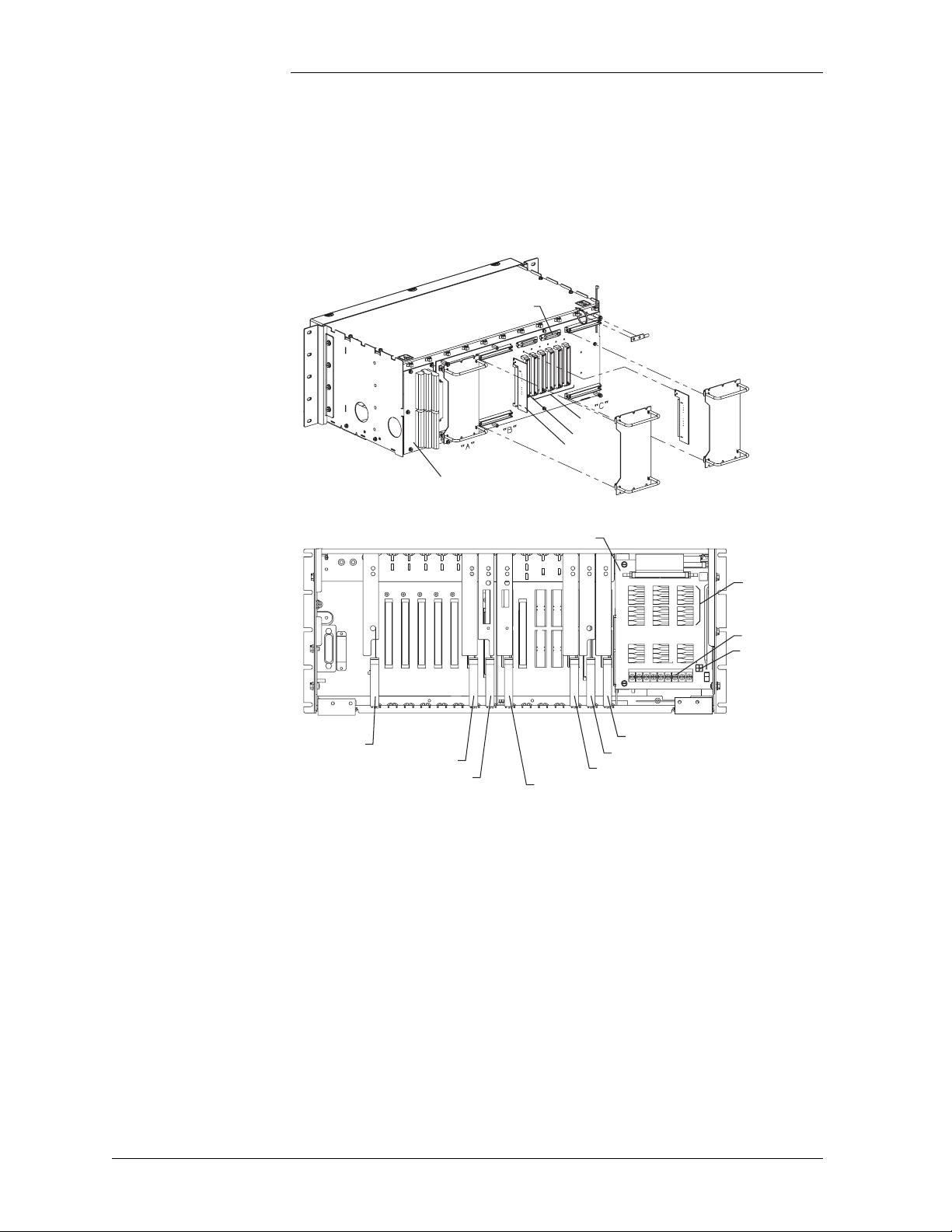
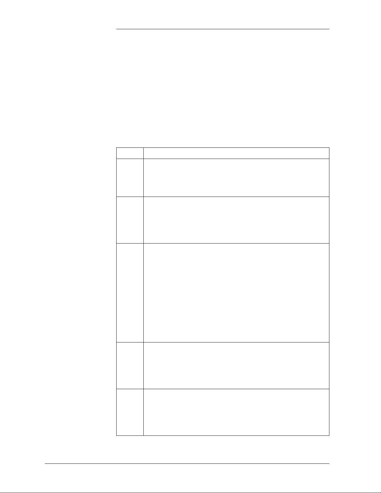
Illustrations Refer to Figures 2-1 and 2-2 for illustrations of the Galaxy SC
Controller.
SC Controller
BJJ Intelligent
Power Board
BJT Termination Board
Options Slot 5
BJL Modem Board
BJH Intelligent Controller
Options Slot 4
Options Slot 3
Options Slot 2
Local PC
Port - RS232
Rear View
Option
Modem
Aux Port
BJF Termination
Fuse Board
BJE Alarm Board
BJA Independent Power Board
BJB Independent Controller
BJC Rectifier Interface Board
Regulation
Fuses
TB1
P500
Figure 2-1: Location of Galaxy SC Controller Circuit Boards
2 - 2 Galaxy SC Controller Performance Verification Procedures Issue 3 January 2008
Page 15
Galaxy Power System Verification Procedures
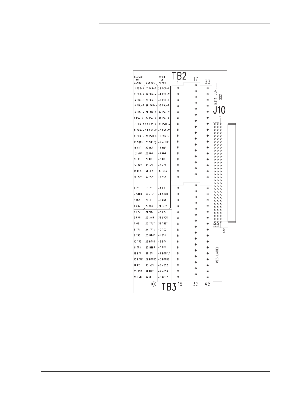
Illustrations, continued
16
32
48
1
FG
17
33
BJT Board
(Galaxy SC Controller)
Figure 2-2: TB2 and TB3 of Galaxy SC Controller
Issue 3 January 2008 Galaxy SC Controller Performance Verification Procedures 2 - 3
Page 16
Galaxy Power System Verification Procedures
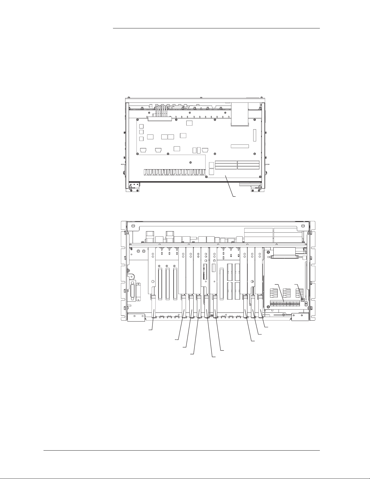
Illustrations, continued
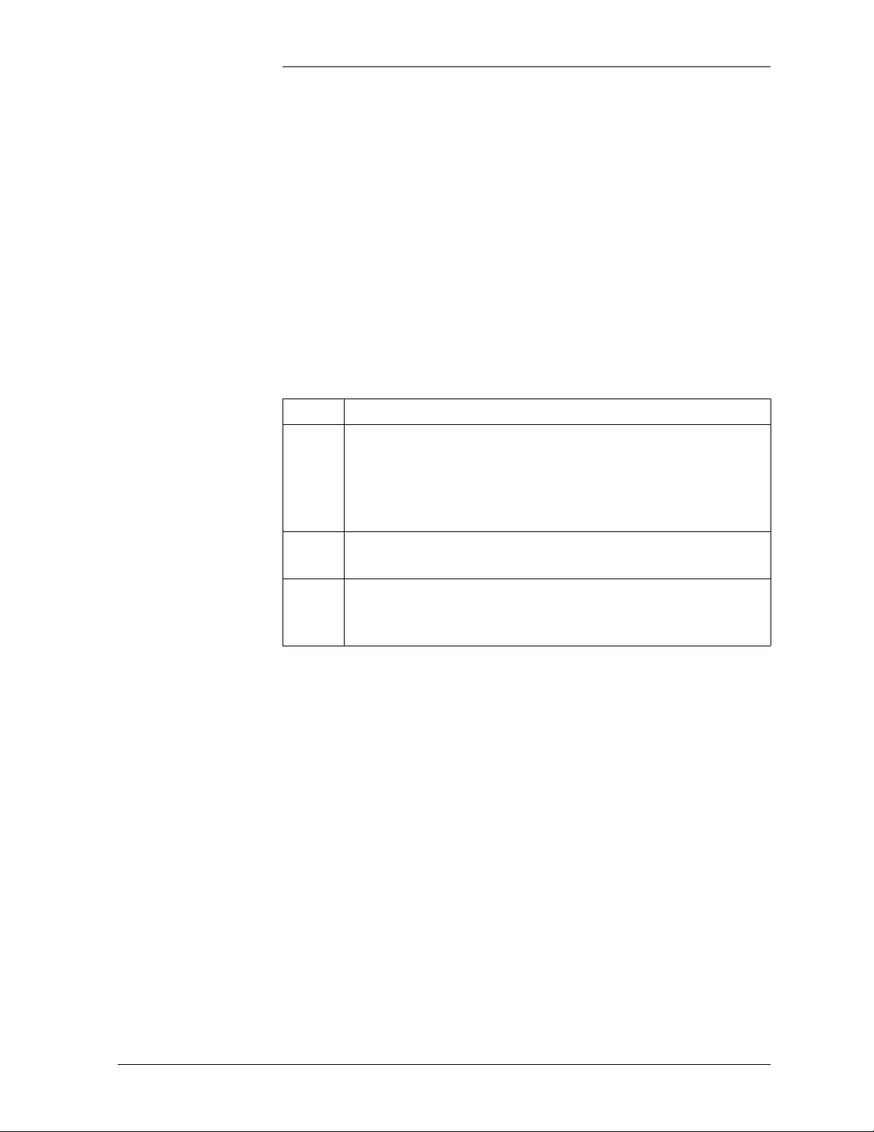
SCF Controller Figures 2-3 and 2-4 are illustrations of the Galaxy SCF Controller.
J2
J1
TB10
J5
P401 P403
TB12
TB11
TB6
Options Slot 4
Options Slot 5
TB7
TB8
J111
J112
BLG1
P110
TB5
TB4
P100
Top View
TB2 TB3
BLG Termination Board
Front View (Door Removed)
TB2 TB3
BJF Termination
Fuse Board
P500TB1
BJJ Intelligent
Power Board
BJK Data Switch
BJM RPM Board
BJL Modem Board
BJB Basic Controller
BJH Intelligent Controller
BJE Alarm Board
BJA Basic Power Board
BJC Rectifier Interface Board
Figure 2-3: Location of Galaxy SCF Controller Circuit Boards
2 - 4 Galaxy SC Controller Performance Verification Procedures Issue 3 January 2008
Page 17
Galaxy Power System Verification Procedures
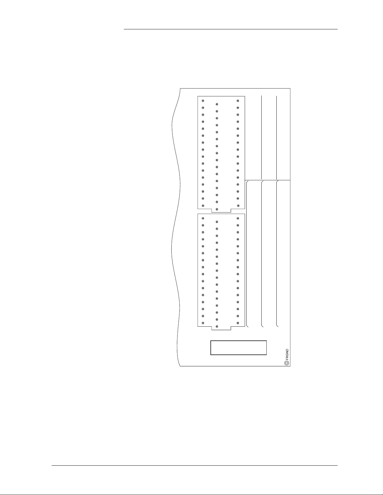
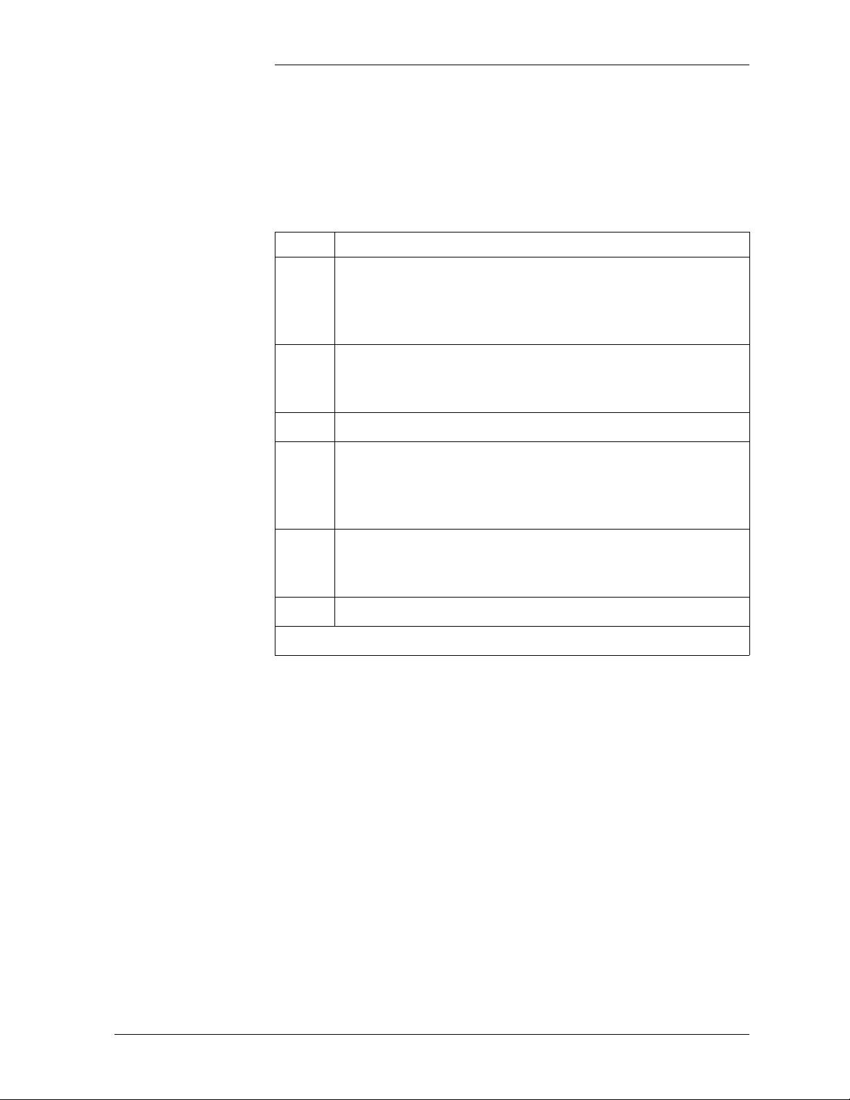
Illustrations, continued
48
48
47
46
45
44
43
42
41
40
TB3
39
38
37
36
35
34
33
48
47
46
45
44
43
42
41
40
TB2
39
38
37
36
35
34
33
33
32
17
16
32
31
30
29
28
27
26
25
24
23
22
21
20
19
18
17
32
31
30
29
28
27
26
25
24
23
22
21
20
19
18
17
16
15
14
13
12
11
10
9
8
7
6
5
4
3
2
1
16
15
14
13
12
11
10
9
8
7
6
5
4
3
2
1
1
48 OPT 2
47 ABS4
46 ABS2
45 BTPDB
44 BTPFLT
43 BTP
42 BTN
41 BTJ
40 TEQ
39 TBST
38 LVDR
37 LVD
36 UR2
35 UR1
34 CTLR
33 HV
48 VLV
47 RFA
46 ACF
45 BD
44 MNF
43 MJF
42 ALRMD
41 PMN-E
40 PMN-V
39 PMN-A
38 PMJ-E
37 PMJ-V
36 PMN-A
35 PCR-E
34 PCR-V
33 PCR-A
OPEN
ON
ALARM
32 OPT1
31 ABS3
30 ABS1
29 BTPDG
28 BTI
27 BTPR
26 BTNR
25 BTJR
24 TRTN
23 TFLT
22 AMN
21 AMJ
20 UR2
19 UR1
18 CTLR
17 HV
32 VLV
31 RFA
30 ACF
29 BD
28 MNF
27 MJF
26 SIR(C)
25 PMN-E
24 PMN-V
23 PMN-A
22 PMJ-E
21 PMJ-V
20 PMJ-A
19 PCR-E
18 PCR-V
17 PCR-A
RETURN
16 LVDF
15 ROR
14 RO
13 ETRR
12 ETR
11 T R4
10 TR3
9 TR2
8 TR1
7 OS
6 FAN
5 FAJ
4 UR2
3 UR1
2 CTLR
1 HV
16 VLV
15 RFA
14 ACF
13 BD
12 MNF
11 M JF
10 SI(C)
9 PMN-E
8 PMN-V
7 PMN-A
6 PMJ-E
5 PMJ-V
4 PMJ-A
3 PCR-E
2 PCR-V
1 PCR-A
CLOSED
ON
ALARM
Part of BLG Board
(Galaxy SCF Controller)
Figure 2-4: TB2 and TB3 of Galaxy SCF Controller
Issue 3 January 2008 Galaxy SC Controller Performance Verification Procedures 2 - 5
Page 18

Galaxy Power System Verification Procedures
Lamp Test Depress the <LAMP TEST> key on the controller’s front display
interface. All LEDs on the controller front panel, controller boards, and
Lucent serial rectifiers will turn on momentarily and then retire.
Alarm Test
Introduction Alarm Test provides a method of testing the operation of all or any of
the plant alarm relays and their wiring to the connected alarm system.
This test cannot be done if any alarms are active. It may also be desirable
to perform this test occasionally after the plant is in service to verify the
integrity of the office alarms for the power plant.
Alarm Test may be performed locally or from a remote terminal.
The Alarm Test feature will, in succession, operate each of the controller
alarm relays. With the basic controller, the default duration is one
minute. With the intelligent option for the controller, the selection of the
relays to be operated and default duration can be changed using the
EasyView interface.
Local Alarm Test Refer to Figures 2-1 and 2-2 for the SC Controller, and to Figures 2-3
and 2-4 for the SCF Controller.
SW202-5 on the BJB Basic Control Board must be enabled along with
its associated software switch found on the front panel under the path:
MAIN → CONFIG → ALARM → TEST ALM.
If HVSD is desired during the test, BJB SW202-4 must also be enabled,
along with the appropriate software switch found on the front panel
under the path: MAIN → CONFIG → ALARM → TEST HV. Each
rectifier in the plant must have a load of at least 10% of its capacity.
When configured with the optional intelligent controller, the alarm
conditions tested during Alarm Test and their duration may be specified
within EasyView with the path: MAIN → CONFIGURE → ALARM
TEST. As an alternative to the front panel configuration of the Alarm
Test software switch, it may be also configured within EasyView under
the path: CONFIGURE → DC PLANT → HARDWARE &
SOFTWARE CONFIGURED.
Note: Front panel LEDs do not activate during the alarm test. The
alarm relays whose contacts are accessed on TB2 and TB3 (BJT board
on rear of SC controller/BLG on top section of the SCF controller) may
be monitored to follow the progress of alarm testing.
2 - 6 Galaxy SC Controller Performance Verification Procedures Issue 3 January 2008
Page 19

Galaxy Power System Verification Procedures
Alarm Test, continued
Local Alarm Test,
continued
The Alarm Test will operate, in sequence, each of the relays shown
below for a default interval of approximately 60 seconds. This interval
for each relay's activation during this test may optionally be set in an
intelligent controller via EasyView path: MAIN → CONFIGURE →
ALARM TEST.
Initiate Alarm Test locally by momentarily pressing the Alarm Test
switch recessed into the front of the BJB basic controller or press the
<MENU> key to bring up the MAIN screen and follow the path:
MAINT OPER → ALARM TEST. The ALM TEST STAT field of this
same screen can then be used to follow the progress of the Alarm Test.
The progress of the activated relays can be followed during the test by
going straight down the TB2 and TB3 terminal blocks if the connected
alarm system is not yet processing. (See Figure 2-2 for the SC, Figure
2-4 for the SCF.) The progress of relay activation may also be monitored
in the ALM TST STAT field of the MEASURE/STATIS screen of an
Intelligent controller or the MAIN screen in the basic controller.
Rectifier Fail Alarm Test - RFAT*
Power Critical - PCR
Power Major - PMJ
Power Minor - PMN
Major Fuse - MJF
Minor Fuse - MNF
Battery on Discharge - BD
AC Fail - ACF
Rectifier Fail Alarm - RFA
Very Low Voltage - VLV/UR3**
High Voltage - HV
Controller - CTLR
User Relay 1 - UR1**
User Relay 2 - UR2**
*RFAT is an alarm test intended for use with non-serial type rectifiers
that are connected to the “Enhanced Ferro” RIM (J85501F-1 L32) of an
SC controller ONLY.
**UR1, UR2, and UR3 are inhibited if LVD Contactors have been
configured and a Bay Interface Card is not configured in the system.
Note: If the controller has an earlier version of software (<6.0), VLV is
used instead of UR3.
Issue 3 January 2008 Galaxy SC Controller Performance Verification Procedures 2 - 7
Page 20

Galaxy Power System Verification Procedures
Alarm Test, continued
Remote Alarm Test Using EasyView to perform the Alarm Test, hardware switches
SW202-5 on the BJB board and SW204-2 on the BJH board must first
be enabled, in addition to the software switches located at menu path.
EasyView: CONFIGURE → DC PLANT → HARDWARE AND
SOFTWARE CONFIGURED
Both the Alarm Test and Remote Alarm Test fields must be enabled.
Initiate the test remotely with the EasyView path:
CONTROL → ALARM TEST.
Follow the status of the test remotely with the EasyView path:
STATUS → ALARM TEST.
2 - 8 Galaxy SC Controller Performance Verification Procedures Issue 3 January 2008
Page 21

Galaxy Power System Verification Procedures
High Float Voltage Alarm/High Voltage Shutdown Alarm Tes t s
Overview The High Float Voltage Alarm Test differs depending on whether
the system uses parallel or serial rectifiers. Both are described in
this section.
The HV test can be done by either raising the plant voltage above the
threshold set for HFV (High Float Voltage) and HVSD (High Voltage
Shutdown) or by lowering the thresholds for these conditions to make
them active.
Note: HFV is an alarm-only that can notify users of an impending HV
condition before the need for a shutdown arises.
Preparations Note the value of plant voltage from the Default screen. Use the
following table to record settings before beginning the test procedures
for both parallel and serial rectifiers:
Plant Nominal Float
Voltage
HV HFV
Issue 3 January 2008 Galaxy SC Controller Performance Verification Procedures 2 - 9
Page 22
Galaxy Power System Verification Procedures
High Float Voltage Alarm/High Voltage Shutdown Alarm
Tests, continued
HV/HVSD Test Procedure for Parallel Rectifiers
Do not raise the plant bus voltage if an active load is being served. To
test HVSD under this situation, ensure that sufficient battery reserve is
connected to the plant bus to support the plant load. The battery may
start sharing some load and BD alarms may turn on during this test.
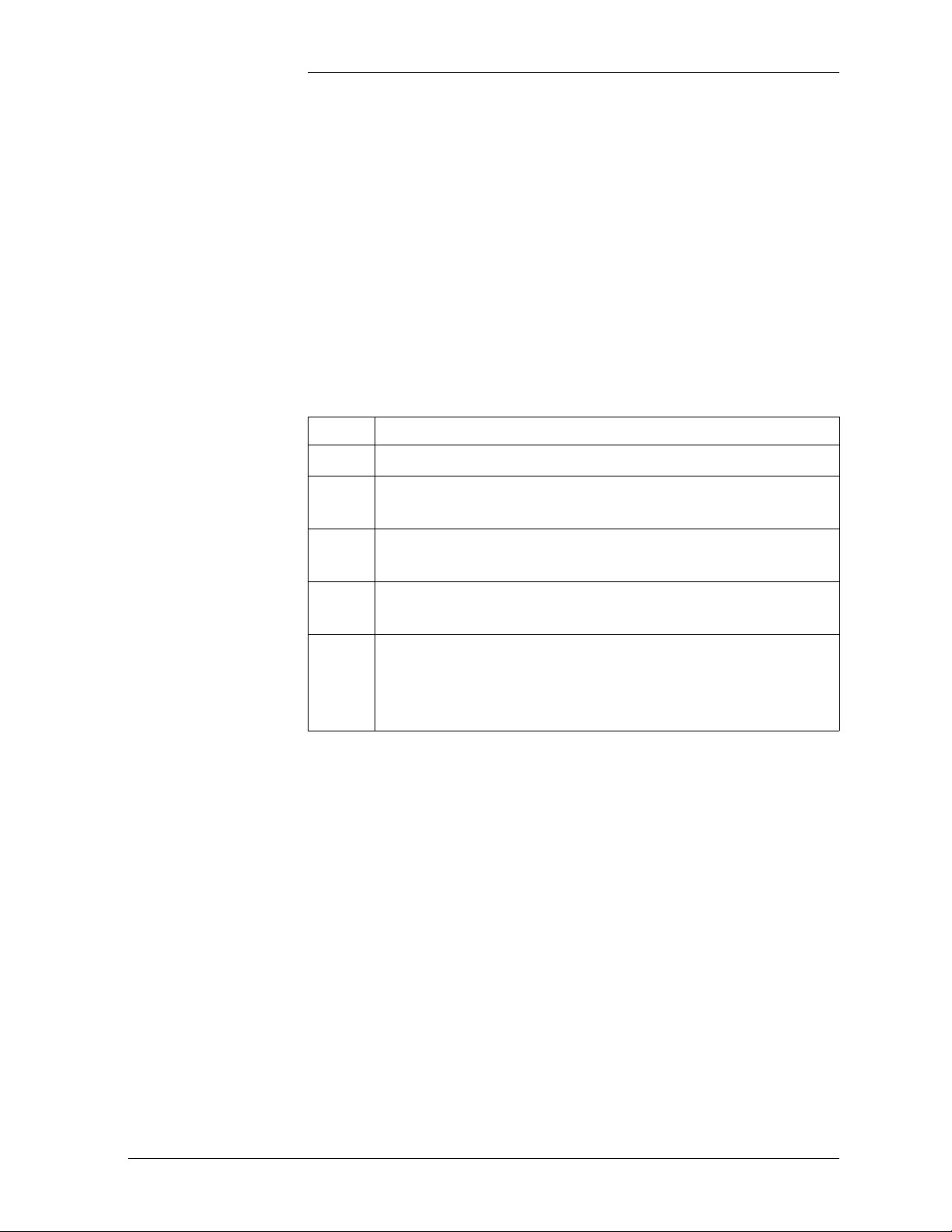
Step Action
1
Disable Load Share on the rectifiers (if equipped) and adjust
the rectifier voltages until each is delivering at least 10% of
its capacity. Turn Off unneeded rectifiers if necessary to
accomplish this.
2
From the Front Display interface, use the path: MAIN →
CONFIG → THRESH and lower the HFV/Float level to 1
volt below the current float voltage. Verify that the Power
Minor relay has activated and the RECT and Minor LEDs
are active.
3
Next, use the path: MAIN → CONFIG → THRESH and
lower the HV/Float level to 1 volt below the current float
voltage. This should activate HVSD, turning Off all plant
rectifiers and placing the plant into a BD (Battery on
Discharge) condition. The BD, RECT, and Major LEDs
should all activate, along with the Power Major, BD, and
RFA alarm relays. After 5 seconds, all rectifiers will restart
and, following walk-in, will begin raising the plant back to
float. When the voltage passes the new HV threshold again,
HVSD will occur again and all rectifiers will remain locked
Off.
4
Use the path: MAIN → CONFIG → THRESH one final
time to reset the HFV and HV Float levels to their desired
normal settings (refer to table where initial settings have
been recorded) and then the path: MAIN → RECT RST to
restart all plant rectifiers, retiring the BD and RECT alarms.
5
Repeat the test for any rectifiers that were turned Off to
achieve the 10% minimum load capacity level of each
rectifier. After all rectifiers have been tested, adjust each to
plant float, if necessary, and reenable Load Share on the
rectifiers, if equipped.
2 - 10 Galaxy SC Controller Performance Verification Procedures Issue 3 January 2008
Page 23
Galaxy Power System Verification Procedures
High Float Voltage Alarm/High Voltage Shutdown Alarm
Tests, continued)
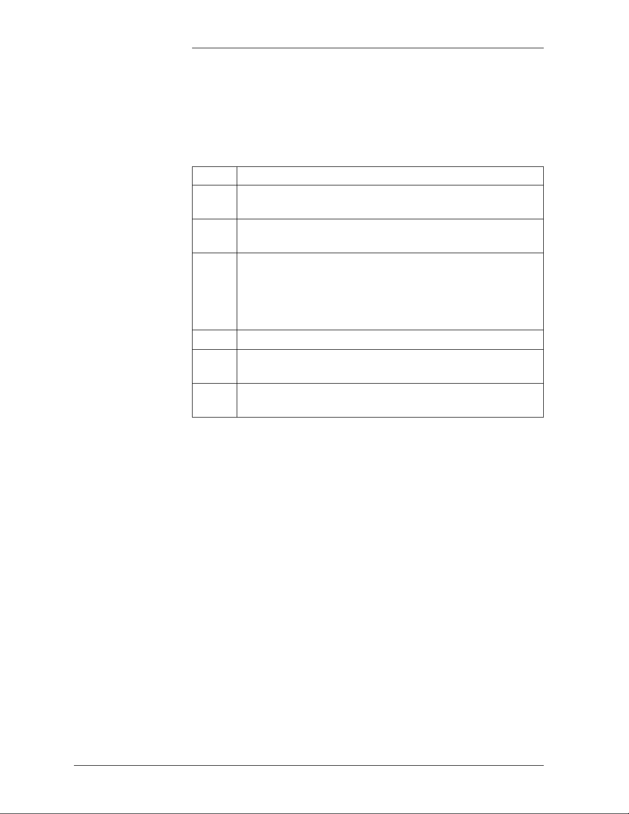
HFV Test Procedure for Serial Rectifiers
Raising the plant voltage on a working system is left to the discretion of
the user. This test could disrupt power to working equipment. If the test
is performed, verify that the plant is in FLOAT mode and that rectifier
voltage has been set to the normal level after completing the test.
Tests must be done with batteries connected, or else when the rectifiers
shut down, the controller will also shut down.
Step Action
1
From the front panel, follow the path <MENU> → CONFIG
→ THRESH → HFV (FLOAT). Use the <Adjust> keys to
change the value of the HFV threshold to a level below the
plant voltage noted above. Press <ENTER> to save the
change.
2
Observe that the controller initiates a Power Minor alarm
(PMN) and illuminates the RECT and MIN LEDs.
3
Follow the path <MENU> → CONFIG → THRESH →
HFV (FLOAT) and restore the threshold to it's original
setting. Press <ENTER> to save the change.
Issue 3 January 2008 Galaxy SC Controller Performance Verification Procedures 2 - 11
Page 24

Galaxy Power System Verification Procedures
High Float Voltage Alarm/High Voltage Shutdown Alarm
Tests, continued))
HVSD Test Procedure for Serial Rectifiers
There are three requirements for a serial rectifier to shut down upon a
controller-initiated High Voltage Alarm:
• The plant voltage must be above the level set for HV at the front
panel path: <MENU> → CONFIG → THRESH.
• The rectifier must be delivering a current exceeding 10% of it's
capacity.
• The rectifier's current output must be unbalanced by more than 10%
from the average output currents of the other rectifiers. Because this
is difficult to achieve in a simulation test of properly functioning
serial rectifiers, even with load share disabled, rectifiers are tested
one at a time rather than as a group. Slightly different test
procedures are used for special applications in batteryless plants.
Serial rectifiers have their own internal restart circuits that will function
3 times before the rectifier locks itself out and initiates a High Output
Rectifier Fail Alarm to the controller. If there is a sufficient interval
between restart and a subsequent shutdown the rectifier resets its restart
counter.
The controller initiates a restart signal a few seconds after the first RFA
(HO) alarm is received. After the second RFA (HO) is received, the
controller waits 5 minutes before sending one additional restart signal.
Do not raise the plant bus voltage if an active load is being served. To
test HVSD under this situation, ensure that sufficient battery reserve is
connected to the plant bus to support the plant load. The battery may
start sharing some load and BD alarms may turn on during this test.
2 - 12 Galaxy SC Controller Performance Verification Procedures Issue 3 January 2008
Page 25
Galaxy Power System Verification Procedures
High Float Voltage Alarm/High Voltage Shutdown Alarm
Tests, continued)
HVSD Test
Procedure for
Serial Rectifiers,
continued
Step Action
1
Turn Off all rectifiers except the rectifier under test by
operating their power switches to STANDBY. Ensure that
the system is loaded to at least 10-90% of the rectifiers’
output capacity.
2
From the front panel follow the path <MENU> → CONFIG
→ THRESH and note the value of the HV (FLOAT)
threshold.
3
Press the <ESC> key to return to the Configuration screen.
4
Follow the path RECT MNGR → [RECT OPER] →
PLANT V (FLOAT) from the Configuration screen.
Note: Menu item in [] used in intelligent controllers only.
5
Use the <ADJUST> keys to change the value of the plant
voltage to a level above the HV (FLOAT) setting noted
above.
6
Press <ENTER> to save the change.
Continued on next page.
Issue 3 January 2008 Galaxy SC Controller Performance Verification Procedures 2 - 13
Page 26
Galaxy Power System Verification Procedures
High Float Voltage Alarm/High Voltage Shutdown Alarm
Tests, continued)
HVSD Test
Procedure for
Serial Rectifiers,
continued
Step Action
Observe the following:
7
• When the voltage increases to the HV (FLOAT) level the
rectifier shuts down.
• The Green ON LED on the rectifier blinks, the ALM
LED on the rectifier is not lit.
• After 5-6 seconds the rectifier initiates its own restart
signal again, raising the plant voltage.
• The rectifier will shutdown and restart three additional
times.
• Upon the fourth shutdown, the rectifier's ALM LED
lights and the rectifier's display indicates “HO.”
• The controller receives the RFA signal from the rectifier
and initiates a restart signal 5-6 seconds later.
• The rectifier restarts again, raising plant voltage.
• The rectifier shuts down and restarts four additional
times.
• During these shutdowns the Green ON LED on the
rectifier blinks, the ALM LED on the rectifier is not lit.
• Upon the fourth shutdown, the rectifier's ALM LED
lights and the rectifier’s display indicates “HO.”
• An external RFA office alarm is generated.
Continued on next page.
2 - 14 Galaxy SC Controller Performance Verification Procedures Issue 3 January 2008
Page 27

Galaxy Power System Verification Procedures
High Float Voltage Alarm/High Voltage Shutdown Alarm
Tests, continued)
HVSD Test
Procedure for
Serial Rectifiers,
continued
Step Action
8
The controller will wait 5-6 minutes and issue one final
restart signal, initiating the final sequence of shutdown and
restart events before the rectifier locks out, requiring
personnel intervention.
Prior to this occurring do the following:
a. From the front panel follow the path <MENU> →
CONFIG → RECT MNGR → [RECT OPER] → PLANT
V (FLOAT).
Note: Menu item in [] used in intelligent controllers only.
b. Use the <ADJUST> keys to change the value of the plant
voltage to its normal level. Press <ENTER> to save the
change.
c. Press <MENU> and select MAINT OPER → RECT
RESTART. Press <ENTER> to restart the rectifier.
Note: Restarting the rectifier from the front panel in this
manner, rather than toggling the rectifier's ON/
STANDBY switch, resets the HVSD timer so that another
rectifier can be tested immediately. Testing of the
additional rectifiers in the same manner is at the user’s
discretion
.
Issue 3 January 2008 Galaxy SC Controller Performance Verification Procedures 2 - 15
Page 28

Galaxy Power System Verification Procedures
Battery on Discharge Alarm Test
Introduction If the BD alarm was observed during the High Voltage Shutdown test
this test can be disregarded.
If the BD alarm was not observed during the HVSD test, perform the
following test procedure:
Procedure
Step Action
1
From the front panel follow the path <MENU> → CONFIG
→ THRLD and observe the setting of the BD (FLOAT)
threshold.
2
Switch some of the rectifiers to STANDBY or OFF, until the
remaining rectifiers go into a current limit and plant voltage
drops below BD (FLOAT) threshold. Observe the active BD
and MAJ LEDs and asserted PMJ and BD relays.
3
Restart the rectifiers to retire alarms and return the plant
voltage to float.
Another way to perform the test is to increase the BD threshold above
the normal plant float voltage, using the following steps:
Step Action
1
From the front panel follow the path <MENU> → CONFIG
→ THRLD and observe the setting of the BD (FLOAT)
threshold.
2
Increase the BD threshold value above the float voltage.
Observe the active BD and MAJ LEDs and asserted PMJ
and BD relays.
3
Reset the BD alarm to the original setting.
2 - 16 Galaxy SC Controller Performance Verification Procedures Issue 3 January 2008
Page 29
Galaxy Power System Verification Procedures
Rectifier Fail Alarm Test
Introduction If the RFA alarm was observed during the High Voltage Shutdown Test
no separate test is required.
If the High Voltage Shutdown Test is not performed, generate an RFA
(Rectifier Fail Alarm) in each of the plant rectifiers individually, using
the procedures below:
Lucent Serial Rectifiers 595 and 596 Series
J855- or J874-Series Rectifiers
For Lucent 595 and 596 Series rectifiers, follow the steps in the table
below:
Step Action
1
2
Turn the rectifier Off. Wait for the rectifier to power down.
Insert a plastic stick between the front panel grills to block
the fan rotation.
3
Turn the rectifier On. After several seconds, the rectifier
will issue an RFA alarm and the plant will generate a PMN.
4
Remove the fan obstruction and toggle the power switch
Off and back On to restart the rectifier and retire the alarm.
5
Generate an RFA (Rectifier Fail Alarm) in each of the plant
rectifiers individually and verify that the RECT and
MINOR LEDs become active along with the Power Minor
and RFA alarm relays.
For Lineage Power J855-series or J874-series rectifiers an RFA is easily
accomplished by operating the “+V” or “-V” fuse alarm circuit by
inserting a paper clip into the alarm indicating hole of the fuse holder.
Issue 3 January 2008 Galaxy SC Controller Performance Verification Procedures 2 - 17
Page 30
Galaxy Power System Verification Procedures
Rectifier Fail Alarm Test, continued
150A SMR Rectifiers
For Lineage Power J85702E-series (150A SMR) rectifiers an RFA may
be generated by using the following procedure:
Step Action
1
Set the rectifier to the Single Power Module Assembly
(PMA) Fail option by placing BGB SW100-8 to OPEN.
2
Set the Output CB switch of all three PMAs inside the
rectifier to the Off position,
3
Raise the rectifier voltage (measured via the rectifier voltage
test jacks on the front panel of the rectifier) above the
Backup HVSD level for the rectifier (set via
SW 100-6/7 on the BGB display/control card of the
rectifier).
4
Verify the RFA in the controller.
5
Lower the rectifier voltage once again to plant float and
restart it to retire the RFA.
6
Close the PMA Output CB switch of all three PMAs and
verify normal rectifier operation
Note: Load share should be disabled (BGB SW100-5) anytime rectifier
voltage is adjusted in these rectifiers with the PMA Output CBs closed.
2 - 18 Galaxy SC Controller Performance Verification Procedures Issue 3 January 2008
Page 31

Galaxy Power System Verification Procedures
Rectifier Fail Alarm Test, continued
50A SMR Rectifiers
Use the following procedure to generate an RFA in Lineage Power 50A
SMR Series rectifiers:
Step Action
1
Set the Output CB switch of the rectifier to the Off position.
2
Raise the rectifier voltage (measured via the rectifier voltage
test jacks on the front panel of the rectifier) above the
Backup HVSD level for the rectifier (set via SW100-6/7 on
the front of the rectifier).
3
Verify RFA in the controller.
4
Lower the rectifier voltage once again to plant float and
restart it to retire the RFA.
5
Close the Output CB switch and verify normal rectifier
operation.
Note: Load share should be disabled (BGB SW100-5) anytime that
rectifier voltage is adjusted in these rectifiers with the Output CBs
closed.
If an intelligent controller is being tested, History for all tested alarms
can be reviewed under the front panel path: MAIN → HISTORY.
Issue 3 January 2008 Galaxy SC Controller Performance Verification Procedures 2 - 19
Page 32

Galaxy Power System Verification Procedures
Terminate Rectifier (TR) Test
Introduction The TR test may be performed even if rectifier sequencing is not
planned to be utilized, as it provides a convenient means of testing that
the controller recognizes all plant rectifiers and is able to control each
over their assigned ports.
Refer to Figures 2-1 and 2-2 for the BJT board of the rear access SC
controller and to Figures 2-3 and 2-4 for the BLG board of the front
access SCF controller.
Test Procedure One at a time, connect a test lead on the TB3 terminal block of the BJT
(SC) or BLG (SCF) termination board, from position 13 (ETRR/
Ground) to position 8 (TR1), 9 (TR2), 10 (TR3), and 11 (TR4). The
rectifiers will shut down in groups as depicted below and remain Off
until the connection is removed at which time they automatically restart.
TR1: G01, G02, G09, G10, G17, G18
TR2: G03, G04, G11, G12, G19, G20
TR3: G05, G06, G13, G14, G21, G22
TR4: G07, G08, G15, G16, G23, G24
Caution: When this test is performed on a live plant, it may cause a
battery discharge (BD) to occur. Ensure that the battery reserve is able
to support the plant load.
2 - 20 Galaxy SC Controller Performance Verification Procedures Issue 3 January 2008
Page 33

Galaxy Power System Verification Procedures
Fuse Alarm Test
Major Fuse Alarm Major Fuse Alarm may be tested by placing a blown fuse in the alarm
fuse position of any distribution fuse position in the plant or by inserting
a paper clip into the alarm indicating hole of its fuse holder. For
distribution circuit breakers, temporarily connect the pins 8 and 9 of any
KS22010 or KS22012 style circuit breakers of any breaker together.
For GPS cabinets, fuse alarms may be simulated at the BNL1 or BNL7
alarm card by strapping FAJ on these cards to the hot bus (P4-1 for
BNL1, P5-6 for BNL7).
The DIST and MAJ LEDs and Power Major and MJF alarm relays will
be active. Alarms should be tested in each distribution bay of the plant
to verify the integrity of the alarm bus throughout the plant. If the
distribution bays are equipped with “Bay Fuse Alarm” indicating LEDs,
also verify that this LED activates during these tests for the bay in which
the alarm originates (and not in any other).
For GPS cabinets, the alarm lamp of the cabinet containing the
controller will always activate, in addition to the cabinet containing the
alarm.
Minor Fuse Alarm Refer to Figures 2-1 and 2-3, respectively, for location of the BJF fuse
termination board in the SC and SCF controllers.
Minor Fuse Alarm may be tested by placing a blown fuse in the alarm
fuse position of the plant Capacitor Charge circuit (if equipped) or by
inserting a paper clip into the alarm indicating hole of its fuse holder.
Alternately, replace one of the unused regulation fuses of the BJF fuse
termination board with a blown GMT type fuse. In either case, the MIN
and either DIST or RECT panel LEDs will activate, along with the
Power Minor and MNF alarm relays.
Issue 3 January 2008 Galaxy SC Controller Performance Verification Procedures 2 - 21
Page 34

Galaxy Power System Verification Procedures
Modem/Data Switch
Remote Peripheral Monitoring
If the Modem (L-AE) and/or Data Switch (L-AH) options have been
provided, they can be tested after wiring and configuration is completed
by dialing into the modem port and, if equipped, passing through to the
devices wired to the equipped Data Switch ports. Refer to the controller
product manual for the T1.317 Data Switch commands required.
Note: If the controller is regularly accessed using a modem, from a
remote monitoring station, this test may not be necessary.
If the Remote Peripheral Monitoring option (L-AG) and J85501G1
monitoring units have been equipped, each channel configured may be
tested for accuracy with a clamp-on ammeter (for Shunt Monitor
channels), voltmeter (for Voltage Monitor channels), or thermometer
(for Temperature channels). If alarms have been configured through the
use of User Defined Event (UDE), they may also be tested by adjusting
their program line to move the thresholds or by adjusting the channel
programming to change the value reported for the channel. Refer to the
Remote Peripheral Monitoring System product manual for complete
feature descriptions of each of these optional monitoring devices.
Rectifier Sequencing
Once set, it is not recommended to change these UDE program lines,
unless it is attempted by a qualified and skilled professional. Refer to the
product manual if it is required to make any adjustments/changes to the
RPM modules or UDE.
If Rectifier Sequencing in an intelligent controller has been enabled (via
EasyView path: MAIN → CONFIGURE → RECTIFIERS), testing can
be completed by temporarily using a shorting clip across TB3 positions
12-13 (ETR/ETRR) on BJT board of the rear access SC controller
(Figure 2-2) and the BLG board of the front access SC controller (Figure
2-4). This will cause all rectifiers configured for Rectifier Sequencing
control to shut Off. Releasing this clip will then cause the rectifiers to
restart sequentially in the manner in which they have been programmed.
2 - 22 Galaxy SC Controller Performance Verification Procedures Issue 3 January 2008
Page 35

Galaxy Power System Verification Procedures
Energy Management
Overview The Energy Management algorithm exercises all rectifiers on a monthly
basis, guaranteeing that every connected rectifier is operated for at least
24 hours each month. All connected rectifiers that have not operated a
total of 24 hours in the previous monthly cycle will be turned on by the
controller on the first Wednesday of the next month at 10:00 a.m. for 24
hours.
Energy Management is available only in the intelligent controller and
must be enabled in both hardware and software. Enable the hardware
switch by setting SW204-1 on the BJH board to 1. From the front panel
follow the path: <MENU> → CONFIG → RECT CTR → EFFIC to
enable the software switch. Energy Management can be enabled in
EasyView by following the path: CONFIGURE → PLANT →
HARDWARE AND SOFTWARE.
Energy Management is enabled only if all connected rectifiers provide
a load signal to the controller via the VI (Voltage proportional to Load)
circuit within each Lucent J855-series or J874-series rectifier control
circuitry. Controllers using the BJC2 rectifier interface packs, used with
rectifiers that do not issue VI signals, instead monitor the mV signal
directly off the rectifier load shunt. In either case, the Energy
Management algorithm requires that the individual rectifier loads be
reported to the controller accurately. Verify that the load reported via
front panel or EasyView path against each rectifier agrees with the
actual load calculated from its shunt mV reading or read from its front
panel. If necessary, adjust the VI circuit of each rectifier as outlined in
the appropriate rectifier product manual. Accuracy of 2% should be
achieved.
Note: It may not be necessary to perform the following Energy
Management test procedure if the rectifiers used are Lineage Power
serial rectifiers. Also, if a TR (terminate rectifier) status is observed on
the LED display, it indicates that the Energy Management feature is
functioning.
Issue 3 January 2008 Galaxy SC Controller Performance Verification Procedures 2 - 23
Page 36

Galaxy Power System Verification Procedures
Energy Management, continued
Procedure
Step Action
1
Reset the BJH intelligent controller (see Figure 2-3) and
stabilize the load at some level at which at least one rectifier
becomes unnecessary. After 10 minutes the first unneeded
rectifier will be turned Off by the controller. If additional
rectifiers can be shut down, they will follow individually at
10 minute intervals.
2
If the plant load can be varied, increase it to the point where
another rectifier is necessary after the controller has
completed its shutdowns. One (or more as required) of the
rectifiers will be restarted immediately when the load
exceeds the capacity of the current on-line rectifiers
3
Observe that the BD alarm is inhibited during the rectifier
walk-in period.
2 - 24 Galaxy SC Controller Performance Verification Procedures Issue 3 January 2008
Page 37

Galaxy Power System Verification Procedures
Meter Calibration from the Front Panel
Voltage Calibration
Step Action
1
Using a calibrated DVM, measure the plant voltage from the
front panel voltage test jacks.
2
From the front panel press <MENU> → CONFIG → PLANT.
Using the Arrow keys, reset the plant voltage reading by
selecting RST PLV. Press <ENTER> to reset. This will
remove any pre-existing user calibrated values if they exist.
3
Press the <MENU> key, wait five seconds, and go back to the
CONFIG → DC PLT screen. Move to ADJ PLV on the menu
and use the <ADJUST> keys to calibrate the plant voltage to
match the reading of the DVM. Press <ENTER> to use the
new calibrated plant voltage.
4
Press the <ESCAPE> key until the default screen is displayed.
Verify that the plant voltage reading reflects the same reading
as shown on the DVM. Note that in a serial plant, the actual
plant voltage reflected by the DVM will change, not the
reading reflected on the display.
Issue 3 January 2008 Galaxy SC Controller Performance Verification Procedures 2 - 25
Page 38

Galaxy Power System Verification Procedures
Meter Calibration from the Front Panel, continued
Current Calibration
The following procedure is applicable only in plants with Load shunts
in a plant configured for “Centralized Architecture.”
Step Action
1
Using a calibrated DVM, measure the plant load from the
front panel current test jacks in mV.
2
To calculate the plant load, in amperes, as measured by the
DVM, divide the mV DVM reading by the rated shunt mV
value. Multiply this result by the shunt ampere rating. This
value is the plant load measured by the DVM, in amperes.
3
From the front panel press <MENU> → CONFIG → PLANT.
Using the Arrow keys, reset the plant current reading by
selecting RST PLI. Press the <ENTER> key to reset. This will
remove any pre-existing user calibrated values if they exist.
4
Press the <MENU> key, wait five seconds, and go back to the
CONFIG → PLANT screen. Move to ADJ PLI on the menu
and use the <ADJUST> keys to calibrate the plant load to
match the calculated plant load value. Press <ENTER> to use
the new calibrated plant load.
5
Press the <ESCAPE> key until the default screen is displayed.
Verify that the plant load reading reflects the new value.
2 - 26 Galaxy SC Controller Performance Verification Procedures Issue 3 January 2008
Page 39

Galaxy Power System Verification Procedures
Battery Discharge Test
Overview The Battery Discharge Test feature dynamically tests the health of the
system’s batteries by controlling rectifier voltage to allow the batteries
to discharge into the plant load. A Bell Labs patented algorithm collects
battery information during the discharge and predicts the battery reserve
time. To initiate the test, the plant must be operating in the Float mode
with no active alarms and only serial type rectifiers connected. The test
is completed when approximately 20 percent of anticipated battery
capacity is removed. During the test, slope thermal compensation and
boost modes will be temporarily disabled. The controller Reserve Time
field will display “Test in Progress” and the BAT LED and the BD
external alarm relay will be activated. BD and Very Low Voltage alarm
thresholds will be temporarily inhibited.
It is a good practice to do a discharge test on the batteries, at least once
a year, or more frequently, if required.
Note: The Battery Discharge Test is for informational and planning
purposes only. It does not constitute the basis for warranty resolutions.
The battery test is aborted if any of the following conditions occur:
• 100 minutes elapses and 20 percent capacity has not been removed
• Battery voltage declines to the highest of the following computed
values:
– (1.75 x No. of cells) + 1.2 [48V] or + .6 [24V]
– Highest LVD disconnect threshold + 1.2 [48V] or + .6 [24V]
– Converter disconnect threshold + 1.2 [48V] or + .6 [24V]
– (Configured end cell voltage x No. of cells) + 1.2 [48V] or + .6
[24V]
• A voltage sense fuse operates
• A rectifier fail alarm occurs
• Any serial communication failure occurs
• Any power major alarm occurs
Issue 3 January 2008 Galaxy SC Controller Performance Verification Procedures 2 - 27
Page 40

Galaxy Power System Verification Procedures
Battery Discharge Test, continued
Overview,
continued
Discharge Menu This menu allows you to configure the various parameters for the
The intelligent controller provides an enhanced battery discharge test
that makes even greater accuracy possible. Enabling the
“ENHANCED” software switch utilizes the Universal Reserve Time
Prediction algorithm, which takes into account the particular discharge
characteristics of the battery subsystem. The URPT feature requires that
battery temperature be monitored and several related battery parameters
be configured. Ensure that the correct battery model is chosen for the
plant.
Note: The Battery Discharge Test feature is available with controller
software Version 6.5 for the SC controller.
Battery Discharge Test and Reserve Time Predictor features of the
controller:
MENU → BATTERY MANAGEMENT → BAT DISCH
BATTERY DISCHARGE TEST
BAT TEST : EN ENHANCED : EN
BAT TYPE : EN CELL STRING : 12
NUM STRING: 24 END V/CELL : 1.75
BAT CLASS : FLOODED
BAT TEST: Enable Battery Discharge Test by using the <+> and <->
keys to toggle between enable or disable. Press <ENTER> to save.
ENHANCED: Use the <+> and <-> keys to enable enhanced feature, if
intelligent controller is present.
BAT TYPE: Use the <+> and <-> keys to select the battery installed on
site. (The Menu contains a list of 10 batteries.) Press <ENTER> to save.
Note: This feature is only available with the intelligent option.
CELL STRING: Use the <+> and <-> keys to select the number of
cells per string. (Select 12 for a 24V plant, or 24 for a 48V plant.) Press
<ENTER> to save.
2 - 28 Galaxy SC Controller Performance Verification Procedures Issue 3 January 2008
Page 41

Galaxy Power System Verification Procedures
Battery Discharge Test, continued
Discharge Menu,
continued
Configuration Configuration may be done locally at the front panel or remotely via
NUM STRING: Use the <+> and <-> keys to select the number of
strings installed on the site. (Range is 1 to 32 strings, default is 2.) Press
<ENTER> to save.
END V/CELL: Use the <+> and <-> keys to select the cell voltage at
the end of the discharge test. (Default value is 1.75V, and is adjustable
between 1.75V and 1.95V.) Press <ENTER> to save.
BAT CLASS: Use the <+> and <-> keys to select flooded or sealed.
Press <ENTER> to save. Note: Use this feature only is the basic
controller is present.
EasyView interface.
Basic: MENU → CONFIG.. → BAT TEST
Intelligent: MENU → CONFIG.. → BAT MNGR → BAT DISCH..
EasyView: CONFIG → BATTERY MANAGEMENT → RESERVE
To initiate the test, the plant must be operating in the Float mode with
no active alarms and only serial type rectifiers connected. The test can
be controlled either locally at the front panel or remotely via EasyView
interface by toggling the BAT DISCH TST software switch.
Basic: MENU → MAINT OPER.. → BAT DISCH TST
Intelligent: MENU → MAINT OPER.. → BAT DISCH TST
EasyView: CONTROL → BATTERY TEST
Issue 3 January 2008 Galaxy SC Controller Performance Verification Procedures 2 - 29
Page 42

Galaxy Power System Verification Procedures
Battery Discharge Test, continued
Procedure
Step Action
1
Enable BATT TEST:
MENU → BATTERY MANAGEMENT → BAT DISCH
Note: Once the other parameters on this screen are configured,
do not modify until any system changes are made.
2
Press <ENTER> to confirm test to proceed. Controller will
perform the battery discharge test.
3
Ve r if y :
• BD alarm will turn On and Status LED will show Green
(NORM).
• Controller display will show BATT TEST at bottom left
and RESERVE TEST IN PROGRESS on bottom right.
4
To abort Battery Discharge Test:
a. Follow menu path
MENU → ΜΑΙΝΤ ΟPER → BAT DISCH TST
b. Verify that display shows “Battery Discharge Test
Aborted.”
Note: The Battery Discharge Test is for informational and planning
purposes only. It does not constitute the basis for warranty resolutions.
If the test is aborted due to an alarm, the Reserve Time message is
displayed as “Alarm Abort” and a user clearable minor alarm is
generated. If the test is aborted due to any of the other conditions shown
above, the Reserve Time message is displayed as “Check Battery” and
a user clearable minor alarm is generated.
2 - 30 Galaxy SC Controller Performance Verification Procedures Issue 3 January 2008
Page 43

Galaxy Power System Verification Procedures
Battery Discharge Test, continued
Test Completion The test is completed when approximately 20 percent of anticipated
battery capacity is depleted.
At the completion of the test, BD and VLV alarm thresholds continue to
be inhibited for 3 additional minutes to allow the batteries to recharge.
A successful test displays the calculated value in the Reserve Time field;
default menu in the intelligent controller or menu path MENU →
MAINT OPER.. in the basic controller. Reserve time in EasyView is
displayed at menu path: STATUS → DC PLANT.
Issue 3 January 2008 Galaxy SC Controller Performance Verification Procedures 2 - 31
Page 44

Page 45

Galaxy Power System Verification Procedures
3 Galaxy Millennium Controller
Performance Verification
Procedures
Introduction The procedures in this section may be used to test the different alarms in
a live Galaxy Millennium Controller system.
Follow the steps of the procedures in the order they are given.
Tools The following tools are required to complete the tests described in this
section:
• Digital Voltmeter (DVM) with dc accuracy of at least 0.05%
• Short length of wire or clip lead for jumper
• Jeweler’s screwdriver
Precautions Before performing the test procedures, verify that the following
conditions exist:
• All rectifiers are functioning properly.
• Plant batteries are fully charged and are ready to support a load.
(See Caution below.)
Caution: When Alarm Tests are performed on a live plant, some of
the tests will cause a battery discharge to occur. In this case, ensure
that the plant batteries are capable of supporting the load. It is
recommended that a battery discharge test be performed before
proceeding with other tests.
Follow the steps of the procedures in the order they are given.
Issue 3 January 2008 Galaxy Millennium Controller Performance Verification Procedures 3 - 1
Page 46

Galaxy Power System Verification Procedures
Lamp Test Depress the <LAMP TEST> key on the controller’s front display
interface. All LEDs on the controller front panel, controller boards, and
Lucent serial rectifiers will turn on momentarily and then retire.
Alarm Test
Overview Alarm Test provides a method of testing the operation of all or any of
the plant alarm relays and their wiring to the connected alarm system.
This test cannot be done if any alarms are active. It may also be desirable
to perform this test occasionally after the plant is in service to verify the
integrity of the office alarms for the power plant. Alarm Test may be
performed locally or from a remote terminal.
The Alarm Test feature will, in succession, operate each of the controller
alarm relays. With the basic controller, the default duration is one
minute. With the intelligent option for the controller, the selection of the
relays to be operated and default duration can be changed using the
EasyView interface.
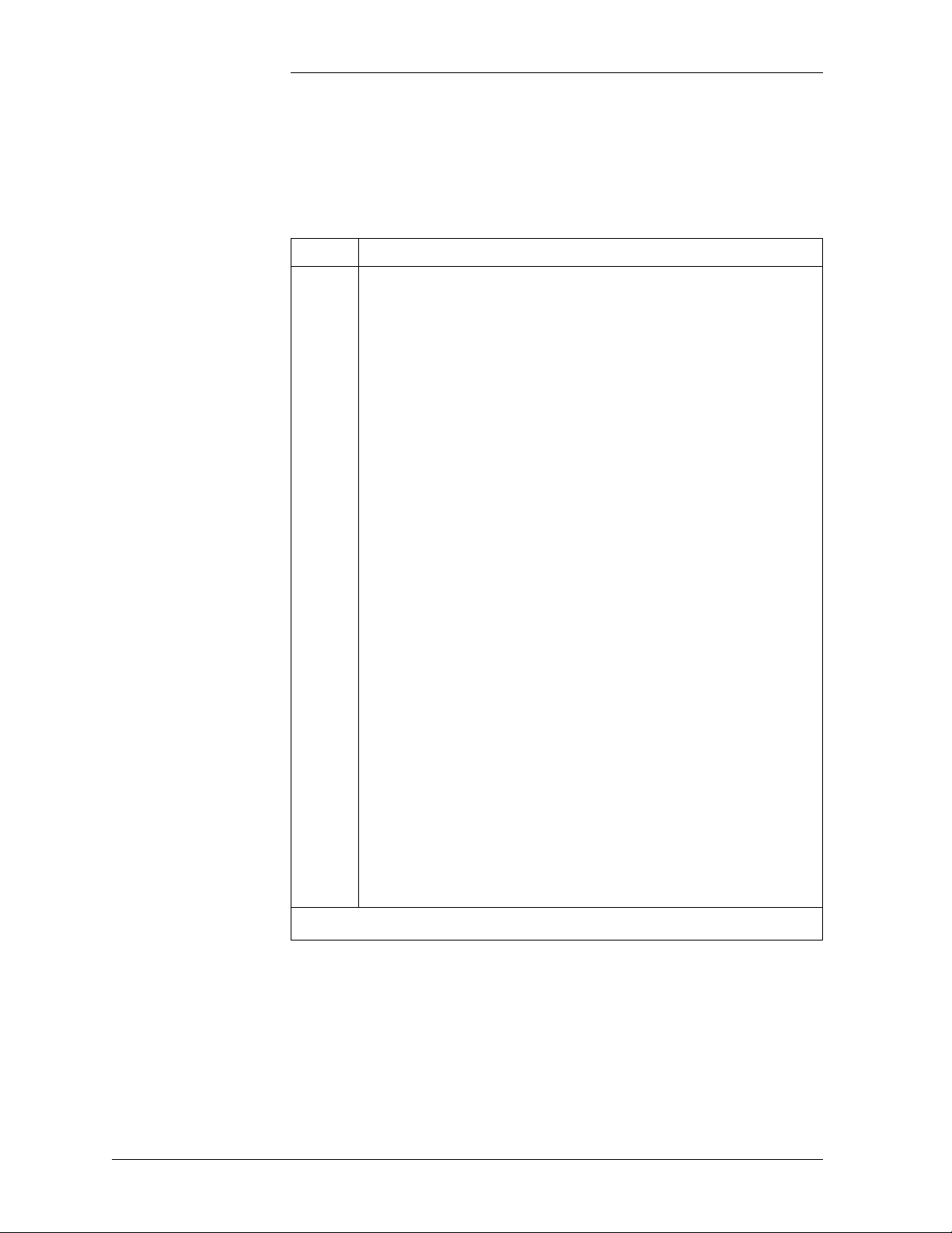
Switch Positions Figure 3-1 shows the switch positions referred to in these procedures.
Controller Fuses
F1 F2 F3 F4 F5
BSM Modem Board
BSH Basic Controller Board
BSJ Intelligent Controller Board
F1 - Option Power
F2 - Intelligent Power
F3 - Basic Power
F4 - Voltage Sense
F5 - Alarm Battery Supply (ABS)
BSL Alarm Termination Board
SW204 (on BSJ Board)
SW202 (on BSH Board)
BSW Data Switch Board
(mounting location)
Figure 3-1: Galaxy Millennium Controller Switch Positions
3 - 2 Galaxy Millennium Controller Performance Verification Procedures Issue 3 January 2008
Page 47

Galaxy Power System Verification Procedures
Alarm Test, continued
Local Alarm Test Refer to Figure 3-1 for the Millennium switch positions referred to in
this test.
Prior to performing an Alarm Test, hardware switch SW202-5 on the
BSH board must be enabled, in addition to the software switch located
at menu path:
Basic: <MENU> → CONFIG → ALARM → TEST ALM
Intelligent: <MENU> → CONFIG → ALARM → TEST ALM
If HVSD is desired during the test, BSH SW202-4 must also be enabled,
along with the appropriate software switch found on the front panel
under the path: MAIN → CONFIG → ALARM → TEST HV, and each
plant rectifier must have a load of at least 10% of its capacity.
To perform the Alarm Test from the front panel, follow the menu path:
Basic: <MENU> → MAINT OPER → ALARM TEST
Intelligent: <MENU> → MAINT OPER → ALARM TEST
As an alternative to the front panel configuration of the Alarm Test
software switch, it may be also configured within EasyView under the
path: CONFIGURE → DC PLANT → HARDWARE & SOFTWARE
CONFIGURED.
Pressing the <ENTER> key while the cursor is on the ALARM TEST
field will provide the message “ALARM TEST STARTED.” Use the
<ESC> key to return to the MAINTENANCE OPERATION screen and
follow the relay operation in the ALARM TEST STAT: field. Pressing
<ENTER> while the cursor is on the ALARM TEST field will restart
the test.
Note: Front panel LEDs do not activate during the Alarm Test. the
alarms can be monitored by checking on the BSL alarm board.
Issue 3 January 2008 Galaxy Millennium Controller Performance Verification Procedures 3 - 3
Page 48

Galaxy Power System Verification Procedures
Alarm Test, continued
Local Alarm Test,
continued
The Alarm Test will operate, in sequence, each of the relays shown
below for a default interval of approximately 60 seconds. This interval
for each relay’s activation during this test may optionally be set in an
intelligent controller via EasyView path: MAIN → CONFIGURE →
ALARM TEST.
Initiate Alarm Test locally by pressing the <MENU> key to bring up the
MAIN screen and following the path: MAINT OPER → ALARM
TEST. The ALM TEST STAT field of this same screen can then be used
to follow the progress of the alarm text.
The progress of the activated relays can also be followed during the test
by sensing for continuity on the appropriate positions of the BSL alarm
board if the connected alarm system is not yet processing.
High Voltage Shutdown - HVSD*
Rectifier Fail Alarm Test - RFAT**
Power Critical - PCR
Power Major - PMJ
Power Minor - PMN
Major Fuse - MJF
Minor Fuse - MNF
Battery on Discharge - BD
AC Fail - ACF
Rectifier Fail Alarm - RFA
User Relay 3 - UR3***
High Voltage - HV
Controller - CTLR
User Relay 1 - UR1***
User Relay 2 - UR2***
*HVSD is optional.
**RFAT is an alarm test intended for use with non-serial type rectifiers
and has no function in this test.
***UR1, UR2, and UR3 are inhibited if LVD Contactors have been
configured and a Bay Interface Card is not configured in the system.
Follow the status of the test remotely with EasyView path: STATUS →
ALARM TEST.
3 - 4 Galaxy Millennium Controller Performance Verification Procedures Issue 3 January 2008
Page 49

Galaxy Power System Verification Procedures
Alarm Test, continued
Remote Alarm Test Using EasyView to perform the Alarm Test, hardware switches
SW202-5 on the BSH board and SW204-2 on the BSJ board (Figure
3-1) must first be enabled, in addition to the software switches located
at menu path.
EasyView: CONFIGURE → DC PLANT → HARDWARE AND
SOFTWARE CONFIGURED
Both the Alarm Test and Remote Alarm Test fields must be enabled.
To start the Alarm Test in EasyView, follow the menu path:
EASYVIEW: CONTROL → ALARM TEST
A dialog box will appear with the status of the alarm relays being tested.
See above for the order in which the alarm relays will operate.
The selection of relays to be operated, as well as the duration of relay
operation, may be selected in EasyView by following the menu path:
EASYVIEW: CONFIGURE → ALARM TEST
Issue 3 January 2008 Galaxy Millennium Controller Performance Verification Procedures 3 - 5
Page 50

Galaxy Power System Verification Procedures
High Float Voltage Alarm Test
Introduction The High Voltage Alarm Test can be done by either raising the plant
voltage above the threshold set for HFV (High Float Voltage) or by
lowering the threshold for this condition to make it active.
Note: HFV is an alarm-only that can be used to notify users of an
impending HV condition before the need for a shutdown arises.
Raising the plant voltage on a working system is left to the discretion of
the user. This test could disrupt power to working equipment. If the test
is performed, verify that the plant is in FLOAT mode and that rectifier
voltage has been set to the normal level after completing the test.
Tests need to be done with batteries connected, or else when the
rectifiers shut down, the controller will also shut down.
Preparations Note the value of plant voltage from the Default screen. Use the
following table to record settings before beginning the test procedures:
Plant Nominal Float
Voltage
HV HFV
Testing High Float Voltage Alarms
Step Action
1
From the front panel, follow the path <MENU> → CONFIG
→ THRESH → HFV (FLOAT). Use the <Adjust> keys to
change the value of the HFV threshold to a level below the
plant voltage noted above. Press <ENTER> to save the
change.
2
Observe that the controller initiates a Power Minor alarm
(PMN) and illuminates the RECT and MIN LEDs.
3
Follow the path <MENU> → CONFIG → THRESH →
HFV (FLOAT) and restore the threshold to it's original
setting. Press <ENTER> to save the change.
3 - 6 Galaxy Millennium Controller Performance Verification Procedures Issue 3 January 2008
Page 51

Galaxy Power System Verification Procedures
High Voltage Shutdown Test
Overview A High Voltage Shutdown signal (HVSD) may optionally be sent to the
rectifiers during the alarm test by enabling the hardware switch
SW202-4 on the BSH board and the software switch at menu path:
Basic: <MENU> → CONFIG → ALARM → TEST HV
Intelligent: <MENU> → CONFIG → ALARM → TEST HV
Use the ADJUST <+> <-> keys to change the value of the TEST HV
field, then press <ENTER> to save the change.
Note: The High Voltage Shutdown Test is not recommended for an
existing installation. However, if this test must be done, make sure that
the battery reserve can support the load for the period until the rectifier
is recycled.
Verify the Auto Restart hardware switch at SW202-7 on the BSH board
is set to 1 (Enabled). Verify the software switch for the Auto Restart
feature is enabled from the front panel. MAIN → CONFIG → RECT
CTR → AUTO RST
Issue 3 January 2008 Galaxy Millennium Controller Performance Verification Procedures 3 - 7
Page 52

Galaxy Power System Verification Procedures
High Voltage Shutdown Test, continued
Serial Rectifiers There are three requirements for a serial rectifier to shut down upon a
controller-initiated High Voltage Alarm:
• The plant voltage must be above the level set for HV at the front
panel path: <MENU> → CONFIG → THRESH.
• The rectifier must be delivering a current exceeding 10% of it's
capacity.
• The rectifier's current output must be unbalanced by more than 10%
from the average output currents of the other rectifiers. Because this
is difficult to achieve in a simulation test of properly functioning
serial rectifiers, even with load share disabled, rectifiers are tested
one at a time rather than as a group. Slightly different test
procedures are used for special applications in batteryless plants.
Note: In an active plant with serial rectifiers the plant High Voltage
(HVSD) test can be performed with only one rectifier in operation, in
order to satisfy all three conditions mentioned above.
Serial rectifiers have their own internal restart circuits that will function
3 times before the rectifier locks itself out and initiates a High Output
Rectifier Fail Alarm to the controller. If there is a sufficient interval
between restart and a subsequent shutdown the rectifier resets its restart
counter.
The controller initiates a restart signal a few seconds after the first RFA
(HO) alarm is received. After the second RFA (HO) is received, the
controller waits 5 minutes before sending one additional restart signal.
3 - 8 Galaxy Millennium Controller Performance Verification Procedures Issue 3 January 2008
Page 53

Galaxy Power System Verification Procedures
High Voltage Shutdown Test, continued
Battery Plant HVSD Test
Step Action
1
Turn Off all rectifiers except the rectifier under test by
operating their power switches to STANDBY. Perform these
tests when loads provide 10-90% of the rectifiers output
capacity.
2
From the front panel follow the path <MENU> → CONFIG
→ THRESH and note the value of the HV (FLOAT)
threshold.
3
Press the <ESC> key to return to the Configuration screen.
4
Follow the path RECT MNGR → [RECT OPER] →
PLANT V (FLOAT) from the Configuration screen.
Note: Menu item in [] used in intelligent controllers only.
5
Use the <ADJUST> keys to change the value of the plant
voltage to a level above the HV (FLOAT) setting noted
above.
6
Press <ENTER> to save the change.
Continued on next page.
Issue 3 January 2008 Galaxy Millennium Controller Performance Verification Procedures 3 - 9
Page 54

Galaxy Power System Verification Procedures
High Voltage Shutdown Test, continued
Battery Plant
HVSD Test,
continued
Step Action
7
Observe the following:
• When the voltage increases to the HV (FLOAT) level the
rectifier shuts down.
• The Green ON LED on the rectifier blinks, the ALM
LED on the rectifier is not lit.
• After 5-6 seconds the rectifier initiates its own restart
signal again, raising the plant voltage.
• The rectifier will shutdown and restart three additional
times.
• Upon the fourth shutdown, the rectifier’s ALM LED
lights and the rectifier’s display indicates “HO.”
• The controller receives the RFA signal from the rectifier
and initiates a restart signal 5-6 seconds later.
• The rectifier restarts again, raising plant voltage.
• The rectifier shuts down and restarts four additional
times.
• During these shutdowns the Green ON LED on the
rectifier blinks and the ALM LED on the rectifier is not
lit.
• Upon the fourth shutdown, the rectifier’s ALM LED
lights and the rectifier’s display indicates “HO.”
• An external RFA office alarm is generated
Continued on next page.
3 - 10 Galaxy Millennium Controller Performance Verification Procedures Issue 3 January 2008
Page 55

Galaxy Power System Verification Procedures
High Voltage Shutdown Test, continued
Battery Plant
HVSD Test,
continued
Step Action
8
The controller will wait 5-6 minutes and issue one final
restart signal, initiating the final sequence of shutdown and
restart events before the rectifier locks out, requiring
personnel intervention.
Prior to this occurring do the following:
a. From the front panel follow the path <MENU> →
CONFIG → RECT MNGR → [RECT OPER] → PLANT
V (FLOAT).
Note: Menu item in [] used in intelligent controllers only.
b. Use the <ADJUST> keys to change the value of the plant
voltage to its normal level. Press <ENTER> to save the
change.
c. Press <MENU> and select MAINT OPER → RECT
RESTART. Press <ENTER> to restart the rectifier.
Note: Restarting the rectifier from the front panel in this
manner, rather than toggling the rectifier's ON/STANDBY
switch, resets the HVSD timer so that another rectifier can
be tested immediately. Testing of the additional rectifiers in
the same manner is at the user’s discretion
Issue 3 January 2008 Galaxy Millennium Controller Performance Verification Procedures 3 - 11
Page 56

Galaxy Power System Verification Procedures
Battery on Discharge Alarm Test
Rectifier
Fail Alarm
If the BD alarm was observed during the High Voltage Shutdown test
this test can be disregarded.
If the BD alarm was not observed during the High Voltage Shutdown
test, do the following:
Step Action
1
From the front panel follow the path <MENU> → CONFIG
→ THRLD and observe the setting of the BD (FLOAT)
threshold.
2
Switch some of the rectifiers to STANDBY or OFF, until the
remaining rectifiers go into a current limit and plant voltage
drops below BD (FLOAT) threshold. Observe the active BD
and MAJ LEDs and asserted PMJ and BD relays.
3
Restart the rectifiers to retire alarms and return the plant
voltage to float.
If the RFA alarm was observed during the High Voltage Shutdown Test
no separate test is required.
Tes t
If the High Voltage Shutdown Test is not performed, generate an RFA
(Rectifier Fail Alarm) in each of the plant rectifiers individually, using
the following procedure:
Step Action
1
Turn the rectifier Off. Wait for the rectifier to power down.
2
Insert a plastic stick between the front panel grills to block
the fan rotation.
3
Turn the rectifier On. Wait for a few seconds; the rectifier
must issue an RFA alarm and the plant must generate a
PMN.
4
Remove the fan obstruction and toggle the power switch Off
and back On to restart the rectifier and retire the alarm.
5
Generate an RFA (Rectifier Fail Alarm) in each of the plant
rectifiers individually and verify that the RECT and MINOR
LEDs become active along with the Power Minor and RFA
alarm relays.
3 - 12 Galaxy Millennium Controller Performance Verification Procedures Issue 3 January 2008
Page 57

Galaxy Power System Verification Procedures
Terminate Rectifier (TR) Test
Introduction The TR test may be performed even if rectifier sequencing is not
planned to be utilized, as it provides a convenient means of testing that
the controller recognizes all plant rectifiers and is able to control each
over their assigned ports.
Refer to Figure 3-1 for location of the BSL board.
Procedure One at a time, connect a test lead on the BSL alarm interface terminal
block from position 76 (ETRR/Ground) to position 73 (TR1), 79 (TR2),
85 (TR3), and 80 (TR4). The rectifiers will shut down in groups as
depicted below and remain Off until the connection is removed at which
time they automatically restart.
TR1: G01, G02, G09, G10, G17, G18
TR2: G03, G04, G11, G12, G19, G20
TR3: G05, G06, G13, G14, G21, G22
TR4: G07, G08, G15, G16, G23, G24
Note: This function can be performed by using EasyView.
Caution: When this test is performed on a live plant, it may cause a
battery discharge (BD) to occur. Ensure that the battery reserve is able
to support the plant load.
Issue 3 January 2008 Galaxy Millennium Controller Performance Verification Procedures 3 - 13
Page 58

Galaxy Power System Verification Procedures
Fuse Alarm Test
Introduction If there are any site installed fuses, they can be tested for alarm
functionality by generating alarms for the controller at these points. If
this is not possible, they can be tested by simulating alarm conditions at
the BSL board (see Figure 3-1) on the Millennium Controller by
following the steps given below.
Major Fuse Alarm (FAJ)
Minor Fuse Alarm (FAN)
Connect a jumper (through a 1K resistor) between Pin 63 (FAJ) and
Pin 93 (ABS) on BSL Board (see Tables 3B, 3C and 3D in the
Millennium controller manual for details of these pin assignments).
DIST and MAJ LEDs will light up. MJF default relay will be activated.
For GPS cabinets, fuse alarms may be simulated at the BNL1 or BL7
alarm card by strapping FAJ on these cards to the hot bus (P4-1 for
BNL1, P5-6 for BNL7).
Connect a jumper (through a 1K resistor) between Pin 65 (FAN) and
Pin 93 (ABS) on BSL Board (see Tables 3B, 3C, and 3D in the
Millennium controller manual for details of these pin assignments).
DIST and MIN LEDs will light up. MNF default relay will be activated.
3 - 14 Galaxy Millennium Controller Performance Verification Procedures Issue 3 January 2008
Page 59

Galaxy Power System Verification Procedures
Modem/Data Switch
Remote Peripheral Monitoring
If the Modem (L-AE) and/or Data Switch (L-AH) options have been
provided, they can be tested after wiring and configuration is completed
by dialing into the modem port and, if equipped, passing through to the
devices wired to the equipped Data Switch ports. Refer to the controller
product manual for T1.317 Data Switch commands.
Note: If the controller is regularly accessed using a modem, from a
remote monitoring station, this test may not be necessary.
If J85501G-1 Remote Peripheral Monitoring units have been equipped,
each channel configured may be tested for accuracy with a clamp-on
ammeter (for Shunt Monitor channels), voltmeter (for Voltage Monitor
channels), or thermometer (for Temperature channels). If alarms have
been configured through the use of User Defined channels, they may
also be tested by adjusting their program line to move the thresholds or
by adjusting the channel programming to change the value reported for
the channel.
Once set, it is not recommended to change these UDE program lines,
unless it is attempted by a qualified and skilled professional. Refer to the
product manual if it is required to make any adjustments/changes to the
RPM modules or UDE.
Rectifier Sequencing
If Rectifier Sequencing in an intelligent controller has been enabled (via
EasyView path: MAIN → CONFIGURE → RECTIFIERS), testing can
be completed by temporarily using a shorting clip across BSL2 Alarm
Interface positions 75-76 (ETR/ETRR) This will cause all rectifiers
configured for Rectifier Sequencing control to shut Off. Releasing this
clip will then cause the rectifiers to restart sequentially in the manner in
which they have been programmed.
Issue 3 January 2008 Galaxy Millennium Controller Performance Verification Procedures 3 - 15
Page 60

Galaxy Power System Verification Procedures
Energy Management
Overview The Energy Management algorithm matches the number and ampacities
of all available battery plant rectifiers to the actual plant load
requirements, favoring the shutdown of rectifiers when plant load
requirements are low enough to warrant selected rectifier shutdown,
thus maintaining the battery plant at maximum efficiency without
sacrificing reliability or creating nuisance alarms. The Galaxy controller
continuously monitors the number of connected rectifiers, their
individual ampacities, the actual output current being delivered by each
and the actual office load-current demand.
The Energy Management algorithm exercises all rectifiers on a monthly
basis, guaranteeing that every connected rectifier is operated for at least
24 hours each month. All connected rectifiers that have not operated a
total of 24 hours in the previous monthly cycle will be turned On by the
controller on the first Wednesday of the next month at 10:00 a.m. for 24
hours.
Procedure
Energy Management is available only in the intelligent controller and
must be enabled in both hardware and software. Enable the hardware
switch by setting SW204-1 on the BSJ board to 1. From the front panel
follow the path: <MENU> → CONFIG → RECT CTR → EFFIC to
enable the software switch. Energy Management can be enabled in
EasyView by following the path: CONFIGURE → PLANT →
HARDWARE AND SOFTWARE.
Step Action
1
Reset the BSJ intelligent controller (Figure 3-1) and stabilize
the load at some level at which at least one rectifier becomes
unnecessary. After 10 minutes, the first unneeded rectifier
will be placed in standby by the controller. If additional
rectifiers can be shut down, they will follow individually at 10
minute intervals.
2
If the plant load can be varied, increase it to the point where
another rectifier is necessary after the controller has
completed its shutdowns. One (or more as required) of the
rectifiers will be restarted immediately when the load exceeds
the capacity of the current on-line rectifiers.
Note: If energy management is always enabled, it may not be required
to do this test, especially if some of the rectifiers are in “TR” mode.
3 - 16 Galaxy Millennium Controller Performance Verification Procedures Issue 3 January 2008
Page 61

Galaxy Power System Verification Procedures
Meter Calibration from the Front Panel
Voltage Calibration
Step Action
1
Using a calibrated DVM, measure the plant voltage from the
front panel voltage test jacks.
2
From the front panel press <MENU> → CONFIG → PLANT.
Using the Arrow keys, reset the plant voltage reading by
selecting RST PLV. Press <ENTER> to reset. This will
remove any pre-existing user calibrated values if they exist.
3
Press the <MENU> key, wait five seconds, and go back to the
CONFIG → DC PLT screen. Move to ADJ PLV on the menu
and use the <ADJUST> keys to calibrate the plant voltage to
match the reading of the DVM. Press <ENTER> to use the
new calibrated plant voltage.
4
Press the <ESCAPE> key until the default screen is displayed.
Verify that the plant voltage reading reflects the same reading
as shown on the DVM. Note that in a serial plant the actual
plant voltage reflected by the DVM will change, not the
reading reflected on the display.
Issue 3 January 2008 Galaxy Millennium Controller Performance Verification Procedures 3 - 17
Page 62

Galaxy Power System Verification Procedures
Meter Calibration from the Front Panel, continued
Current Calibration
The following procedure is applicable only in plants with Load shunts
in a plant configured for “Centralized Architecture.”
Step Action
1
Using a calibrated DVM, measure the plant load from the
sense connection points on the plant shunt(s).
2
To calculate the plant load, in amperes, as measured by the
DVM, divide the mV DVM reading by the rated shunt mV
value. Multiply this result by the shunt ampere rating. This
value is the plant load measured by the DVM, in amperes.
3
From the front panel press <MENU> → CONFIG → PLANT.
Using the Arrow keys, reset the plant current reading by
selecting RST PLI. Press the <ENTER> key to reset. This will
remove any pre-existing user calibrated values if they exist.
4
Press the <MENU> key, wait five seconds, and go back to the
CONFIG → PLANT screen. Move to ADJ PLI on the menu
and use the <ADJUST> keys to calibrate the plant load to
match the calculated plant load value. Press <ENTER> to use
the new calibrated plant load.
5
Press the <ESCAPE> key until the default screen is displayed.
Verify that the plant load reading reflects the new value.
3 - 18 Galaxy Millennium Controller Performance Verification Procedures Issue 3 January 2008
Page 63

Galaxy Power System Verification Procedures
Battery Discharge Test
Overview The Battery Discharge Test feature dynamically tests the health of the
system’s batteries by controlling rectifier voltage to allow the batteries
to discharge into the plant load. A Bell Labs patented algorithm collects
battery information during the discharge and predicts the battery reserve
time. To initiate the test, the plant must be operating in the Float mode
with no active alarms and only serial type rectifiers connected. The test
is completed when approximately 20 percent of anticipated battery
capacity is removed. During the test, slope thermal compensation and
boost modes will be temporarily disabled. The controller Reserve Time
field will display “Test in Progress” and the BAT LED and the BD
external alarm relay will be activated. BD and Very Low Voltage alarm
thresholds will be temporarily inhibited.
It is a good practice to do a discharge test on the batteries, at least once
a year, or more frequently, if required.
Note: The Battery Discharge Test is for informational and planning
purposes only. It does not constitute the basis for warranty resolutions.
The battery test is aborted if any of the following conditions occur:
• 100 minutes elapses and 20 percent capacity has not been removed
• Battery voltage declines to the highest of the following computed
values:
– (1.75 x No. of cells) + 1.2 [48V] or + .6 [24V]
– Highest LVD disconnect threshold + 1.2 [48V] or + .6 [24V]
– Converter disconnect threshold + 1.2 [48V] or + .6 [24V]
– (Configured end cell voltage x No. of cells) + 1.2 [48V] or + .6
[24V]
• A voltage sense fuse operates
• A rectifier fail alarm occurs
• Any serial communication failure occurs
• Any power major alarm occurs
Issue 3 January 2008 Galaxy Millennium Controller Performance Verification Procedures 3 - 19
Page 64

Galaxy Power System Verification Procedures
Battery Discharge Test, continued
Overview,
continued
Discharge Menu This menu allows you to configure the various parameters for the
The intelligent controller provides an enhanced battery discharge test
that makes even greater accuracy possible. Enabling the
“ENHANCED” software switch utilizes the Universal Reserve Time
Prediction algorithm, which takes into account the particular discharge
characteristics of the battery subsystem. The URPT feature requires that
battery temperature be monitored and several related battery parameters
be configured. Ensure that the correct battery model is chosen for the
plant.
Note: The Battery Discharge Test feature is available with controller
software Version 6.1 for the Millennium controller.
Battery Discharge Test and Reserve Time Predictor features of the
controller:
MENU → BATTERY MANAGEMENT → BAT DISCH
BATTERY DISCHARGE TEST
BAT TEST : EN ENHANCED : EN
BAT TYPE : EN CELL STRING : 12
NUM STRING: 24 END V/CELL : 1.75
BAT CLASS : FLOODED
BAT TEST: Enable Battery Discharge Test by using the <+> and <->
keys to toggle between enable or disable. Press <ENTER> to save.
ENHANCED: Use the <+> and <-> keys to enable enhanced feature, if
intelligent controller is present.
BAT TYPE: Use the <+> and <-> keys to select the battery installed on
site. (The Menu contains a list of 10 batteries.) Press <ENTER> to save.
Note: This feature is only available with the intelligent option.
CELL STRING: Use the <+> and <-> keys to select the number of
cells per string. (Select 12 for a 24V plant, or 24 for a 48V plant.) Press
<ENTER> to save.
3 - 20 Galaxy Millennium Controller Performance Verification Procedures Issue 3 January 2008
Page 65

Galaxy Power System Verification Procedures
Battery Discharge Test, continued
Discharge Menu,
continued
Configuration Configuration may be done locally at the front panel or remotely via
NUM STRING: Use the <+> and <-> keys to select the number of
strings installed on the site. (Range is 1 to 32 strings, default is 2.) Press
<ENTER> to save.
END V/CELL: Use the <+> and <-> keys to select the cell voltage at
the end of the discharge test. (Default value is 1.75V, and is adjustable
between 1.75V and 1.95V.) Press <ENTER> to save.
BAT CLASS: Use the <+> and <-> keys to select flooded or sealed.
Press <ENTER> to save. Note: Use this feature only is the basic
controller is present.
EasyView interface.
Basic: MENU → CONFIG.. → BAT TEST
Intelligent: MENU → CONFIG.. → BAT MNGR → BAT DISCH..
EasyView: CONFIG → BATTERY MANAGEMENT → RESERVE
To initiate the test, the plant must be operating in the Float mode with
no active alarms and only serial type rectifiers connected. The test can
be controlled either locally at the front panel or remotely via EasyView
interface by toggling the BAT DISCH TST software switch.
Basic: MENU → MAINT OPER.. → BAT DISCH TST
Intelligent: MENU → MAINT OPER.. → BAT DISCH TST
EasyView: CONTROL → BATTERY TEST
Issue 3 January 2008 Galaxy Millennium Controller Performance Verification Procedures 3 - 21
Page 66

Galaxy Power System Verification Procedures
Battery Discharge Test, continued
Procedure
Step Action
1
Enable BATT TEST:
MENU → BATTERY MANAGEMENT → BAT DISCH
Note: Once the other parameters on this screen are configured,
do not modify until any system changes are made.
2
Press <ENTER> to confirm test to proceed. Controller will
perform the battery discharge test.
3
Ve r if y :
• BD alarm will turn On and the Status LED will show
Green (NORM).
• Controller display will show BATT TEST at bottom left
and RESERVE TEST IN PROGRESS on bottom right.
4
To abort Battery Discharge Test:
a. Follow menu path
MENU → ΜΑΙΝΤ ΟPER → BAT DISCH TST
b. Verify that display shows “Battery Discharge Test
Aborted.”
Note: The Battery Discharge Test is for informational and planning
purposes only. It does not constitute the basis for warranty resolutions.
If the test is aborted due to an alarm, the Reserve Time message is
displayed as “Alarm Abort” and a user clearable minor alarm is
generated. If the test is aborted due to any of the other conditions shown
above, the Reserve Time message is displayed as “Check Battery” and
a user clearable minor alarm is generated.
3 - 22 Galaxy Millennium Controller Performance Verification Procedures Issue 3 January 2008
Page 67

Galaxy Power System Verification Procedures
Battery Discharge Test, continued
Test Completion The test is completed when approximately 20 percent of anticipated
battery capacity is depleted.
At the completion of the test, BD and VLV alarm thresholds continue to
be inhibited for 3 additional minutes to allow the batteries to recharge.
A successful test displays the calculated value in the Reserve Time field;
default menu in the intelligent controller or menu path MENU →
MAINT OPER.. in the basic controller. Reserve time in EasyView is
displayed at menu path: STATUS → DC PLANT.
Issue 3 January 2008 Galaxy Millennium Controller Performance Verification Procedures 3 - 23
Page 68

Page 69

Galaxy Power System Verification Procedures
4 Replacement Procedures
Overview This section provides the following replacement procedures:
• Controller
– Memory Battery Replacement for SC and SCF controllers
– Memory Battery Replacement for Millennium controller
• GPS2424
– Installing or Replacing a 596B3 Rectifier
– Replacing a 596B3 Rectifier Fan Assembly
– Replacing a 597A or 597B Converter Carrier
– Replacing a 47A Converter Module
– Replacing a 128A Converter Interface Card
– Replacing a Converter Fan Assembly
• GPS4812
– Installing or Replacing a 596A Rectifier
– Replacing a 596A Rectifier Fan Assembly
• GPS4848
– Installing or Replacing a 595A or 595B Rectifier
– Removing a Rectifier
– Replacing a 595A or 595B Rectifier Fan Assembly
Issue 3 January 2008 Replacement Procedures 4 - 1
Page 70

Galaxy Power System Verification Procedures
Memory Backup Battery Replacement for SC/SCF Controller
Introduction The memory backup battery is located on the BJH (Intelligent
Controller) circuit pack. The battery provides power to retain system
configuration stored in memory in the event the BJH circuit pack is
removed or input power to the Galaxy Controller is interrupted. Battery
life is usually about five years.
When the memory backup battery is low, the Memory Backup Battery
Low warning is active and the battery should be replaced. Perform the
following three procedures to replace the memory backup battery to
prevent loss of system configuration:
• Backup System Configuration
• Replace Memory Backup Battery
• Restore System Configuration
Backup System Configuration
Use the EasyView software to perform a backup of the system
configuration. Refer to the discussion of EasyView in the controller
product manual. (If you need to install EasyView for the first time, see
the Product Manual “EasyView Software for the Galaxy Controller,”
Select Code 193-104-105.) Follow these steps to perform the backup:
Step Action
1
Log in and begin an EasyView session.
2
Open the File menu and select Backup. Select a filename
and directory to store the system configuration. Click OK.
EasyView displays the status of the backup. Click OK when
the Backup operation is completed.
3
Open the Options menu and select Setup Sites. Select your
connection profile from the Site list. Click Modify. Change
the Administrator password to the default password
“administrator.” Change the Connect password to
“administrator.” Click OK. Click Close.
4
Open the Connect menu and select Disconnect to end the
EasyView session.
4 - 2 Replacement Procedures Issue 3 January 2008
Page 71

Galaxy Power System Verification Procedures
Memory Backup Battery Replacement for SC/SCF Controller,
continued
Replace Memory Backup Battery
You must remove the BJH Intelligent Controller circuit pack to replace
the battery. Follow these steps:
Step Action
1
Identify the BJJ Intelligent Power board (far left position)
and pull its circuit pack locking lever forward and downward
to release it from the backplane. Slide the pack straight out
until fully disengaged from the backplane.
2
Identify the BJH Intelligent Controller circuit pack and pull
its locking lever forward and downward to unlock the pack.
Then slide the pack straight out of the card cage.
3
Remove the memory battery. Take care not to flex the
battery holder clip excessively.
4
Insert the memory battery (Panasonic BR2032 or equivalent,
Lucent Comcode 406526079) into the BJH (Intelligent
Controller) circuit pack X201 battery holder. Observe proper
polarity; the battery holder clip contacts the “+” side of the
memory battery. Take care not to flex the battery holder clip
excessively.
5
Align the BJH Intelligent Controller circuit pack with the
circuit pack tracks and carefully slide the circuit pack into
the card cage. Seat and lock the circuit pack into the card
cage by lifting the circuit pack locking lever to the full
upright position.
6
Reengage the BJJ Intelligent power board into the backplane
and lift its circuit pack locking lever into the full upright
position. Observe active green LEDs on all packs after
approximately one minute.
Issue 3 January 2008 Replacement Procedures 4 - 3
Page 72

Galaxy Power System Verification Procedures
Memory Backup Battery Replacement for SC/SCF Controller,
continued
Restore System Configuration
Step Action
1
Log in and begin an EasyView session using the previously
modified connection profile.
2
Open the File menu and click on Restore. Select the
configuration file you saved when you performed the
Backup operation. Click OK. EasyView displays the status
of the backup. Click OK when the Restore operation is
complete.
3
Open the Configure menu and click on Configure
Passwords. Change the passwords from the default setting to
the appropriate password for your site.
4
Open the Options menu and click on Setup Sites. Select your
connection profile from the Site list. Click Modify. Change
the passwords to those from the previous step. Click OK.
Click Close.
5
Open the Connect menu and select Disconnect to end the
EasyView session.
4 - 4 Replacement Procedures Issue 3 January 2008
Page 73

Galaxy Power System Verification Procedures
Memory Backup Battery Replacement for Millennium Controller
Introduction The memory backup battery is located on the BSJ (Intelligent
Controller) circuit pack. The battery provides power to retain system
configuration stored in memory in the event the BSJ circuit pack is
removed or input power to the Galaxy Controller is interrupted. Battery
life is typically about five years.
When the memory backup battery is low, the Memory Backup Battery
Low warning is active and the battery should be replaced. Perform the
following three procedures to replace the memory backup battery to
prevent loss of system configuration:
• Backup System Configuration
• Replace Memory Backup Battery
• Restore System Configuration
Backup System Configuration
Use the EasyView software to perform a backup of the system
configuration. Refer to the discussion of EasyView in Section 4 of this
manual. If you need to install EasyView for the first time, see the
Product Manual “Lineage® 2000 EasyView Software for the Galaxy
Controller,” Select Code 193-104-105.
DANGER
Danger of explosion or fire if lithium battery is incorrectly
replaced. Replace only with a battery recommended by the
manufacturer. Spare batteries may be ordered per the product
documentation. Lithium batteries may be regulated wastes (due to
reactivity) when disposed of. Always discard used batteries
according to applicable local, state, and federal regulations.
CAUTION
Lithium batteries present risk of fire, explosion, and burns. Do not
recharge, disassemble, heat above 100° C (212° F), or incinerate.
Dispose of used batteries promptly. Keep away from children.
Issue 3 January 2008 Replacement Procedures 4 - 5
Page 74

Galaxy Power System Verification Procedures
Memory Backup Battery Replacement for Millennium
Controller, continued
Backup System Configuration
Follow these steps to perform the backup:
Step Action
1
Log in and begin an EasyView session.
2
Open the File menu and select Backup. Select a file name
and directory to store the system configuration. Click OK.
EasyView displays the status of the backup. Click OK when
the Backup operation is completed.
3
If site passwords are not at default, open the Options menu
and select Setup Sites. Select your connection profile from
the Site list. Click Modify. Change the Administrator
password to the default password “administrator.” Change
the Connect password to “administrator.” Click OK. Click
Close.
4
Open the Connect menu and select Disconnect to end the
EasyView session.
4 - 6 Replacement Procedures Issue 3 January 2008
Page 75

Galaxy Power System Verification Procedures
Memory Backup Battery Replacement for Millennium
Controller, continued
Replace Memory Backup Battery
Step Action
1
Remove the memory battery. Take care not to flex the
battery holder clip excessively.
2
Insert the memory battery into the BSJ (Intelligent
Controller) circuit pack X201 battery holder. Observe proper
polarity; the battery holder clip contacts the “+” side of the
memory battery. Take care not to flex the battery holder clip
excessively.
Restore System Configuration
Step Action
1
Log in and begin an EasyView session using the previously
modified connection profile.
2
Open the File menu and click on Restore. Select the
configuration file you saved when you performed the
Backup operation. Click OK. EasyView displays the status
of the backup. Click OK when the Restore operation is
complete
3
Open the Configure menu and click on Configure
Passwords. Change the passwords from the default setting to
the appropriate password for your site.
4
Open the Configure menu and click on System → System
Time. Set the System time and date. Click OK.
5
If passwords are not at system defaults, open the Options
menu and click on Setup Sites. Select your connection
profile from the Site list. Click Modify. Change the
passwords to those chosen for the site. Click OK. Click
Close.
6
Open the Connect menu and select Disconnect to end the
EasyView session.
Issue 3 January 2008 Replacement Procedures 4 - 7
Page 76

Galaxy Power System Verification Procedures
Requirements
System With the exception of the batteries, periodic maintenance specific to the
power system is not required. The ac service for the building must be
maintained with ANSI specified limits. The temperature and humidity
within the power room must be maintained within the limits specified in
the product manual.
Batteries The batteries must be maintained as directed by the battery
manufacturer’s requirements.
Rectifiers With the exception of a fan failure, rectifiers are repaired by
replacement. Refer to “Installing or Replacing a Rectifier” in this
section.
Rectifier Fan Assembly
The expected life of the rectifier fans at 25°C (77°F) is approximately
eight years. The fans in the rectifiers may be replaced in the field.
Two approaches can be taken to fan maintenance:
• The first approach is to replace the fan on a routine basis every
seven to eight years; this ensures that the fan does not fail in the
field under normal operating conditions. This approach is
appropriate when there are no remote alarm facilities at the site.
• The second approach, assuming one has remote alarm capability, is
to wait until the fan fails. The rectifier will safely shut down and
issue both a fail alarm and a thermal alarm. The fan can then be
replaced. Since it is likely that all the rectifiers in that installation
are of roughly the same age, all rectifier fans at that site should be
replaced at that time.
The approach used depends on the location and manning of the site as
well as the monitoring of alarms used at the site. Refer to “Replacing a
Rectifier Fan Assembly” in this section.
Note: As a routine procedure, keep fan assemblies dust-free.
4 - 8 Replacement Procedures Issue 3 January 2008
Page 77

Galaxy Power System Verification Procedures
Requirements, continued
Converters With the exception of a fan failure, converters are repaired by
replacement.The expected life of the converter fans at 25°C (77°F) is
approximately five years. The fans in the converters may be replaced in
the field.
Two approaches can be taken to fan maintenance. The first approach is
to replace the two fans on a routine basis every four to five years; this
ensures that the fans do not fail in the field under normal operating
conditions. This approach is appropriate when there are no remote alarm
facilities at the site. The second approach, assuming one has remote
alarm capability, is to wait until a fan fails. It can then be replaced. Since
it is likely that all the converters in that installation are of roughly the
same age, all converter fans at that site should be replaced at that time.
The approach used depends on the location and manning of the site as
well as the monitoring of alarms used at the site. The fan replacement
procedure is described in this section.
Note: As a routine procedure, keep fan assemblies dust-free.
Issue 3 January 2008 Replacement Procedures 4 - 9
Page 78

Galaxy Power System Verification Procedures
GPS2424 Replacement Procedures
Installing or Replacing a 596B3 Rectifier
Step Action
1
Locate and turn off the ac service feeding the rectifier.
Note: Do not turn off ac service to the entire system, only to
the rectifier that has failed.
2
Turn the rectifier’s ON/STBY switch to STBY.
Rear portion of the rectifier or converter that is in
operation is HOT to the touch. Use appropriate
precautions.
3
(Steps 3 and 4 for replacement only. For a new installation,
proceed to Step 5.)
Caution
Locate the Allen-head bolt in the center of the rectifier front
panel. Using the Allen wrench provided, rotate the bolt
counterclockwise to release the rectifier for removal.
4
Caution
Handle the rectifier or converter using two hands, one
hand supporting the rear of the unit, the other hand on the
front handle.
Grasp the front handle and slide/pull the rectifier from the
shelf assembly. Support the rear of the unit as it slides from
the shelf.
Figure 4-1: Detail of 596B3 Rectifier Position
Continued on next page.
4 - 10 Replacement Procedures Issue 3 January 2008
Page 79

Galaxy Power System Verification Procedures
GPS2424 Replacement Procedures, continued
Installing or
Replacing a 596B3
Rectifier, continued
Step Action
5
Slowly slide new rectifier onto the shelf until it contacts the
rear connector.
6
Using the Allen wrench, turn the Allen-head bolt clockwise
to pull the rectifier into the shelf.
7
Once the rectifier has been installed, set the rectifier ID.
(Refer to product manual.)
Note: The red LED on the rectifier will blink until the
rectifier establishes communication with the controller.
After communication is established, the controller will issue
a RECT MAJ alarm until the rectifier ID is set.
8
Turn the ac service back on.
9
!
Turn the rectifier’s ON/STBY switch to ON.
Issue 3 January 2008 Replacement Procedures 4 - 11
Page 80

Galaxy Power System Verification Procedures
GPS2424 Replacement Procedures, continued
Replacing a 596B3 Rectifier Fan Assembly
Stop! Review the “Installing or Replacing a Rectifier” procedure in this
section before proceeding.
Step Action
1
Remove the rectifier from the system. See the “Installing or
Replacing a Rectifier” procedure in this section.
2
WAIT five minutes for capacitors to discharge.
3
Loosen the white front cover by removing 14 screws (5 top,
5 bottom, 2 on each side). Before fully removing the cover,
disconnect the ribbon cable from the display circuit pack.
4
Remove the screws attaching the old fans to the chassis and
carefully unplug the fan connector. The fan connector is keyed
and can be loosened by inserting a screwdriver into the slotted
side of the connector and gently prying the fan-side connector
loose.
5
Replace the new fans.
6
Reconnect the ribbon cable removed in Step 3.
7
Attach the front cover.
8
Install the rectifier, following instructions in the “Installing or
Replacing a Rectifier” procedure in this section.
4 - 12 Replacement Procedures Issue 3 January 2008
Page 81

Galaxy Power System Verification Procedures
GPS2424 Replacement Procedures, continued
Replacing a 597A or 597B Converter Carrier
Note: This procedure will disconnect the 48V output from the load even
if two carriers are being used.
Step Action
1
Open the carrier door.
2
Remove all converter modules from the carrier to be replaced.
See “Replacing a Converter Module.”
3
Locate the Allen-head retaining screw. See Figure 4-2. Using
the Allen wrench provided, rotate the tool counter-clockwise
to remove the old converter from the shelf.
Note: If two carriers are used, disconnect the shelf-to-shelf
cable as you slide out the carrier. See Figure 4-3.
Fan Latches
Fan Power
Connectors
47A Converter Module
Converter Interface
Card Retaining Screw
(opposite side)
Retaining Screw
Figure 4-2: Detail of Converter Components
Plug Cable into Converter Before
Sliding Converter onto Shelf
848253654 Cable Assembly
Note: Converters must be on adjacent shelves.
Figure 4-3: Cable Connection Between Two Converter
Carriers
Continued on next page.
Issue 3 January 2008 Replacement Procedures 4 - 13
Page 82

Galaxy Power System Verification Procedures
GPS2424 Replacement Procedures, continued
Replacing a 597A
or 597B Converter
Carrier, continued
Replacing a 47A Converter Module
Step Action
4
Turn off the load protectors in the carrier to be replaced and
disconnect the output wiring.
5
To install a converter carrier, slowly slide the carrier into the
shelf until it contacts the rear connector. Remember to
reconnect the carrier cable if two carriers are used.
Turning the Allen key insertion tool clockwise will pull the
carrier into the shelf. See Figure 4-1.
Step Action
1
Open the converter carrier.
Replacing a 128A Converter Interface Card
2
Pull the latch forward and remove the old 47A converter
module.
3
Switch new 47A converter module to STBY.
4
Insert new converter module.
5
Switch converter module ON.
Step Action
1
Remove the retaining screw that holds the converter interface
card in place.
2
Replace the converter interface card.
3
Replace and tighten the retaining screw.
4 - 14 Replacement Procedures Issue 3 January 2008
Page 83

Galaxy Power System Verification Procedures
GPS2424 Replacement Procedures, continued
Replacing a Converter Fan Assembly
Step Action
1
Remove adjacent rectifier from the shelf by loosening the
Allen-head retaining screw.
2
Disconnect the power wire connection.
3
Slide the fan latch to the left.
4
Remove fan assembly.
5
Replace fan assembly.
6
Replace power wire assembly.
7
Slide converter carrier into shelf.
8
Tighten retaining screw.
Issue 3 January 2008 Replacement Procedures 4 - 15
Page 84

Galaxy Power System Verification Procedures
GPS4812 Replacement Procedures
Installing or Replacing a 596A Rectifier
Step Action
1
Locate and turn off the ac service feeding the rectifier.
Note: Do not turn off ac service to the entire system, only to
the rectifier that has failed.
2
Turn the rectifier’s ON/STBY switch to STBY.
Rear portion of the rectifier that is in operation is HOT to
the touch. Use appropriate precautions.
3
(Steps 3 and 4 for replacement only. For a new installation,
proceed to Step 5.)
Locate the Allen-head bolt in the center of the rectifier front
panel. Using the Allen wrench provided, rotate the bolt
counterclockwise to release the rectifier for removal.
Caution
4
Caution
Handle the rectifier using two hands, one hand supporting
the rear of the unit, the other hand on the front handle.
Grasp the front handle and slide/pull the rectifier from the
shelf assembly. Support the rear of the unit as it slides from
the shelf.
Figure 4-4: Detail of 596A Rectifier Position
5
Slowly slide new rectifier onto the shelf until it contacts the
rear connector.
6
Using the Allen wrench, turn the Allen-head bolt clockwise to
pull the rectifier into the shelf.
Continued on next page.
4 - 16 Replacement Procedures Issue 3 January 2008
Page 85

Galaxy Power System Verification Procedures
GPS4812 Replacement Procedures, continued
Installing or
Replacing a 596A
Rectifier, continued
Step Action
7
Once the rectifier has been installed, set the rectifier ID.
Follow the directions in product manual.
Note: The red LED on the rectifier will blink until the
rectifier establishes communication with the controller.
After communication is established, the controller will issue
a RECT MAJ alarm until the rectifier ID is set.
8
Turn the ac service back on.
9
!
Turn the rectifier’s ON/STBY switch to ON.
Replacing a 596A Rectifier Fan Assembly
Stop! Review the “Installing or Replacing a Rectifier” procedure in this
section before proceeding.
Step Action
1
Remove the rectifier from the system. See the “Installing or
Replacing a Rectifier” procedure in this section.
2
WAIT five minutes for capacitors to discharge.
3
Loosen the white front cover by removing 14 screws (5 top,
5 bottom, 2 on each side). Before fully removing the cover,
disconnect the ribbon cable from the display circuit pack.
4
Remove the screws attaching the old fans to the chassis and
carefully unplug the fan connector. The fan connector is keyed
and can be loosened by inserting a screwdriver into the slotted
side of the connector and gently prying the fan-side connector
loose.
5
Replace the new fans.
6
Reconnect the ribbon cable removed in Step 3.
7
Attach the front cover.
8
Install the rectifier, following instructions in the “Installing or
Replacing a Rectifier” procedure in this section.
Issue 3 January 2008 Replacement Procedures 4 - 17
Page 86

Galaxy Power System Verification Procedures
GPS4848 Replacement Procedures
Installing or Replacing a 595A or 595B Rectifier
Stop! Be sure ac breakers on cabinet are OFF!
Step Action
1
Unpack the rectifier from shipping container.
Caution
Rectifier is heavy (65 pounds). Use two people to lift and
move rectifiers.
2
Remove rectifier by lifting the unit in a vertical direction
from the packing container. See figure below.
Caution
Do not rest rectifier on faceplate or rear chassis; damage
to faceplate and/or rear busbars will occur, rendering the
unit unusable.
Lift Straight Up
Continued on next page.
4 - 18 Replacement Procedures Issue 3 January 2008
Page 87

Galaxy Power System Verification Procedures
GPS4848 Replacement Procedures, continued
Installing or
Replacing a 595A
or 595B Rectifier,
continued
!
Step Action
3
Install the rectifier. See Figure 4-5.
a. Verify the output circuit breaker is OFF and that the
rectifier power switch is in the “Standby” position.
b. Slide the unit slowly onto the shelf until it contacts the
rear connector.
Note: Install rectifiers vertically, starting at the bottom
position and working upward.
c. Remove the label over the access window. Using a 5mm
Allen-head “T” wrench, turn the locking screw clockwise
to secure the rectifier to the shelf.
Rectifier Shelf
in Cabinet
Rectifier
Insertion Tool
Figure 4-5: Installing a Rectifier in a Rectifier Shelf
Continued on next page.
Issue 3 January 2008 Replacement Procedures 4 - 19
Page 88

Galaxy Power System Verification Procedures
GPS4848 Replacement Procedures, continued
Installing or
Replacing a 595A
or 595B Rectifier,
continued
Step Action
4
Turn on ac circuit breaker(s).
5
Turn on power switch on rectifier; turn on output circuit
breaker.
6
Ve r if y :
• Green LED is illuminated.
• No alarms are illuminated.
7
Set rectifier slot ID number:
a. Depress and hold rectifier power switch in UP position for
5 seconds; the displayed number will begin to blink.
b. Depress and release switch until desired number is
reached.
c. When the desired number is reached, continue to hold
switch until display stops blinking. The new ID number is
now set.
Note: Abandoning this process before the display stops
blinking will default the rectifier to the last number set.
8
Follow Step 3 to install remaining rectifiers. Follow Step 7
to set remaining ID numbers.
9
Verify that the rectifier picks up load similar to that of the
others in the system and that the plant voltage is at the level
desired as set by the Rectifier Manager screen.
10
Test replaced rectifiers using the “Testing Additional Alarms
After Replacement of Rectifiers” procedure in this section.
4 - 20 Replacement Procedures Issue 3 January 2008
Page 89

Galaxy Power System Verification Procedures
GPS4848 Replacement Procedures, continued
Removing a Rectifier
Step Action
1
Turn off output circuit breaker on rectifier.
2
Turn off power switch on rectifier.
3
Turn off ac circuit breakers.
4
Wait 5 minutes to allow capacitors to discharge.
5
Using a 5mm Allen-head “T” wrench, slowly turn the
locking screw counterclockwise to release the rectifier from
the shelf.
6
Slowly slide rectifier from shelf.
Caution
Rectifier is heavy (65 pounds). Use two people to lift and
move rectifiers.
Do not rest rectifier on faceplate or rear chassis; damage
to faceplate and/or rear busbars will occur, rendering the
unit unusable.
Issue 3 January 2008 Replacement Procedures 4 - 21
Page 90

Galaxy Power System Verification Procedures
GPS4848 Replacement Procedures, continued
Replacing a 595A or 595B Rectifier Fan Assembly
Step Action
1
Follow instructions in the “Removing a Rectifier” procedure
in this section.
2
Place rectifier on a flat surface at a comfortable working
height.
3
Loosen the front cover (white) by removing 14 screws (5
top, 5 bottom, 2 on each side). Before fully removing the
cover, disconnect the ribbon cable from the display circuit
pack.
Caution
Allow the front end of the rectifier to overhang the
working surface. To remove bottom screws, turn the
rectifier on its side, or work below the table surface.
Never tilt the front of the unit to gain access to the bottom
screws. This will result in damage to the rear connector.
All Screws Shown Except for
Fan Mounting Screws Below
#6-32 x 5/16" (846743656)
Torque to 10 in-lbs (1.1 Nm)
To Display
Threaded Taper Pin
Torque to 10 in-lbs (1.1 Nm)
Fans
(846427839)
Comair PQ4887X-031868
Fan Mounting Screws
#6-32 x 2 1/4" (846427839)
Torque to 10 in-lbs (1.1 Nm)
Figure 4-6: Replacing a Rectifier Fan Assembly
Continued on next page.
4 - 22 Replacement Procedures Issue 3 January 2008
Page 91

Galaxy Power System Verification Procedures
GPS4848 Replacement Procedures, continued
Replacing a 595A
or 595B Rectifier
Fan Assembly,
continued
Step Action
4
Remove the screws attaching the old fans to the chassis and
carefully unplug the fan connector. The fan connector is keyed
and can be loosened by inserting a screwdriver into the slotted
side of the connector and gently prying the fan-side connector
loose.
5
Replace the new fans. Torque fasteners to 10 in-lb.
6
Replace the ribbon cable removed in Step 3.
7
Replace the front cover.
8
Install the rectifier, following the “Installing or Replacing a
Rectifier” procedure in this section.
9
Test replaced rectifiers using the “Testing Additional Alarms
After Replacement of Rectifiers” procedure in this section.
10
Replace the ribbon cable removed in Step 3.
11
Replace the front cover.
12
Install the rectifier, following the “Installing or Replacing a
Rectifier” procedure in this section.
13
Test replaced rectifiers using the “Testing Additional Alarms
After Replacing Rectifiers” procedure in this section.
Issue 3 January 2008 Replacement Procedures 4 - 23
Page 92

Tes t in g
Galaxy Power System Verification Procedures
Testing Additional Alarms After Replacing Rectifiers
Testing Rectifiers and Load Share in Bay Expansions
Alarm operation may be verified while the system operates at float
voltage.
Step Action
1
Turn OFF the ac circuit breaker of replaced rectifier. Verify
that the AC and MIN alarm LEDs illuminate, the rectifier
displays ACF, and the controller alarms screen indicates
RECTIFIER FAIL : G01 (SCF and Millennium controllers).
2
Turn ON the ac circuit breaker of the replaced rectifier.
Verify that the rectifier starts and the alarms retire.
Step Action
1
Turn all rectifiers to STBY.
2
Connect a resistive load box (proper voltage) to the system’s
positive and negative bus bars.
3
Verify that the system load is less than 50 amperes.
4
Increase the system load to 50 amperes.
5
Turn ON all the rectifiers; after approximately 60 seconds,
verify that the load is divided equally among all the
rectifiers (within 2 amperes).
6
Reduce the system load. Verify that the rectifiers continue to
share the load.
7
Remove system load.
4 - 24 Replacement Procedures Issue 3 January 2008
Page 93

Galaxy Power System Verification Procedures
5 Glossary
Please turn to the following pages for glossary terms related to the SC,
SCF, and Millennium Controllers.
Issue 3 January 2008 Glossary 5 - 1
Page 94

Galaxy Power System Verification Procedures
SC Controller Circuit Boards
The following figure shows the location of the Basic and Intelligent
circuit boards in the SC Controller, which are described in the following
pages.
BJJ Intelligent
Power Board
BJT Termination Board
Options Slot 4
Options Slot 3
Options Slot 2
Options Slot 5
BJL Modem Board
BJH Intelligent Controller
Option
Modem
BJF Termination
Fuse Board
BJE Alarm Board
BJA Independent Power Board
BJC Rectifier Interface Board
BJB Independent Controller
Location of Basic and Intelligent Boards in the SC Controller
5 - 2 Glossary Issue 3 January 2008
Page 95

Galaxy Power System Verification Procedures
SC Controller Circuit Boards (Basic)
BJA1 or BJA2
Power Board
BJB1 Digital
Board
BJC1, BJC2 or
BJC3 Rectifier
Interface Boards
Provides the power required by the basic controller, and provides the
hardware high voltage (HV) circuitry.
BJA1 is for 48 volt systems; BJA2 is for 24 volt systems.
Contains the microprocessor, memory, serial interface, chip select logic,
and other digital components used for the basic controller.
BJC1 provides the circuitry to interface with Lineage Power rectifiers
with VI signals, ferroresonant, or switch mode rectifiers (without
rectifier current monitoring).
BJC2 provides the same functions for rectifiers with mV shunt signals:
Lineage Power switch mode and non-Lucent rectifiers. Each board can
control up to eight rectifiers, allowing Galaxy to control a total of 24
rectifiers.
BJC3 (Serial Rectifier Interface Board) provides the circuitry to
interface with Galaxy serial interface switchmode rectifiers and
converters. The BJC3 can control up to 24 serial rectifiers or converters.
BJE1 Relay/Alarm/
Display Driver
Board
BJF1 or BJF2
Termination Fuse
Board
BJG1 Display
Board
BJT1 Termination
Board
Contains the remaining circuitry required by the basic controller. Has
isolation circuits to receive contact closures from other parts of the plant
such as external fuse alarms, TR leads, and external timer float and
boost leads. Contains the alarm relays such as power major and power
minor. Also contains the interface circuits to the front panel display
board (BJG1).
Contains the input power terminal blocks and fuses for the controller.
BJF1 is for negative voltage plants; BJF2 is for positive voltage plants.
Contains the switches, LEDs and eight-line display for the front panel,
providing the primary user interface for the controller. Mounted inside
the front door
Contains the terminal blocks for customer alarm wiring and signal
inputs. This board mounts next to the backplane on the back of the
controller.
Issue 3 January 2008 Glossary 5 - 3
Page 96

Galaxy Power System Verification Procedures
SC Controller Circuit Boards (Intelligent)
BJH Intelligent
Controller Board
BJJ1 or BJJ2
Power Boards
BJK1 Data Switch Operates the Data Switch, an optional interface with XCS, ECS, RAS,
BJL2 Modem
Board
Contains the microprocessor, memory, real time clock, serial interface,
and interface circuitry to the other intelligent circuit packs. Enables
“intelligent” features, including alarm history, battery reserve time
prediction, peripheral monitor and control, etc.
Also provides access to the TL1/X.25 interface.
Provides power to the intelligent controller board and intelligent option
boards.
BJJ1 is for 48 volt systems; BJJ2 is for 24 volt systems.
and OMNIpulse units. Data Switch allows call-in and call-out access to
as many as four RS-232 devices via the Galaxy access ports.
Required for data access over telephone lines. Provides the modem
circuitry needed to interface the controller from a remote location over
the switched telephone network at up to 14,400 baud.
BJM1 Peripheral
Monitoring Board
Required for any peripheral monitoring or control. Provides interface
circuitry for up to 255 remote monitoring modules, allowing
connections to as many as 1,530 monitoring points.
SCF Controller Circuit Boards
The following figure shows the location of the Basic and Intelligent
circuit boards in the SCF Controller, which are described in the
following pages.
5 - 4 Glossary Issue 3 January 2008
Page 97

Galaxy Power System Verification Procedures
J2
J1
TB10
J5
P401 P403
TB12
TB11
TB6
TB8
TB7
J111
Top View
Front View
BLG1
P100
J112
P110
TB5
TB2 TB3
TB4
BLG Termination Board
BJF Termination
Fuse Board
P500TB1
Options Slot 4
Options Slot 5
BJJ Intelligent
Power Board
BJK Data Switch
BJM RPM Board
BJL Modem Board
BJB Basic Controller
BJH Intelligent Controller
BJE Alarm Board
BJA Basic Power Board
BJC Rectifier Interface Board
Location of Basic and Intelligent Boards in the SCF Controller
Issue 3 January 2008 Glossary 5 - 5
Page 98

Galaxy Power System Verification Procedures
SCF Controller Boards (Basic)
BJA1 or BJA2
Basic Controller
Power Board
BJB1 Basic
Controller Digital
Board
BJC3 Serial
Rectifier Interface
Board
BJE2 Relay/Alarm/
Display Driver
Board
This board provides the power required by the basic controller. BJA1 is
for 48-volt systems, BJA2 is for 24-volt systems.
The BJB1contains the microprocessor, memory, serial interface, and
other digital and analog components used for the basic controller.
BJC3 provides the circuitry to interface with Galaxy serial interface
switchmode rectifiers and converters. The BJC3 can control up to
twenty-four serial rectifiers and 8 converters.
Contains the remaining support circuitry required by the basic
controller. Has isolation circuits that receive contact closures from other
parts of the plant such as external fuse alarms, TR leads, and external
timer float and boost leads. Also contains the alarm output relays such
as power major and power minor. Provides the interface circuits to the
front panel display board (BJG1). Also contains Form-C contacts that
may be used for external contactor control.
BJF3 or BJF4
Termination Fuse
Board
BLG1 Front
Access Board
BJG1 Display
Board
Contains the input power terminal blocks and fuses for the controller.
BJF3 is for negative voltage plants; BJF4 is for positive voltage plants.
Mounts above the rest of the circuit packs internal to the chassis.
Provides front access connections to all the customer’s alarm wiring and
signaling inputs.
Mounted inside the front door. Contains the switches, LEDs, and the
eight-line display control for the front panel, providing the primary user
interface for the controller. The display is protected by a lexan cover to
protect against high levels of electrostatic discharge (ESD).
5 - 6 Glossary Issue 3 January 2008
Page 99

Galaxy Power System Verification Procedures
SCF Controller Circuit Boards (Intelligent)
BJJ1 or BJJ2
Intelligent
Controller Power
Boards
BJH Intelligent
Controller Board
BJL2 Modem
Board
BJM1 Peripheral
Monitoring Board
Required for any intelligent features. Provides power to the intelligent
controller board and intelligent option boards.
BJJ1 is for 48 volt systems; BJJ2 is for 24 volt systems.
Required for all the intelligent functions of the Galaxy SCF Controller.
Contains the microprocessor, memory, real time clock, various serial
interfaces, and interface circuitry to the other intelligent circuit packs.
Enables “intelligent” features, including alarm history, battery reserve
time prediction, peripheral monitoring and control, etc.
Also provides access to the TL1/X.25 interface.
Required for data access over telephone lines. Provides the modem
circuitry needed to interface the controller from a remote location over
the switched telephone network at up to 14,400 baud.
Required for any peripheral monitoring or control. Provides interface
circuitry for up to 255 remote monitoring modules, allowing
connections to as many as 1,530 monitoring points.
BJK1 Data Switch Required to operate the Data Switch, an optional interface with XCS,
ECS, RAS, and OMNIpulse units. Data Switch allows call-in and
call-out access to as many as four RS-232 devices via the Galaxy access
ports.
Issue 3 January 2008 Glossary 5 - 7
Page 100

Galaxy Power System Verification Procedures
Millennium Controller Circuit Boards
The following figure shows the location of the Basic and Intelligent
circuit boards in the Millennium Controller, which are described in the
following pages.
BSL Alarm Termination Board
BSW Data Switch Board
(mounting location)
BSJ Intelligent Controller Board
BSH Basic Controller Board
BSM Modem Board
Location of Basic and Intelligent Boards in the Millennium Controller
5 - 8 Glossary Issue 3 January 2008
 Loading...