

Page 1

Installation Guide
for Galaxy Power Systems
Note: Instructions in this manual reference installation and setup of GPS
systems with Galaxy Millennium Controllers and 596 or 596 rectifiers.
For installation and setup with other controllers and rectifiers refer to
these product manuals.
GalaxyMillennium II Product Manual 167-792-181
GalaxyPulsar Plus Product Manual CC848815341
NE Rectifiers
GPS2436 Product Manual 850022020
GPS4827 Product Manual 850022019
Installation Guide
Select Code 167-792-157
Comcode 108327362
Issue 12
August 2012
Page 2

Page 3

Installation Guide
Select Code 167-792-157
Comcode 108327362
Issue 12
August 2012
for Galaxy Power Systems
Installation Guide
Notice:
The information, specifications, and procedures in this manual are
subject to change without notice. Lineage Power assumes no
responsibility for any errors that may appear in this document.
© 2011 Lineage Power
All International Rights Reserved
Printed in U.S.A.
Page 4

Page 5

Installation Guide for Galaxy Power Systems
Table of Contents
1 Introduction
Product Documentation 1-1
This Installation Guide 1-1
Revisions 1-1
Related Documentation 1-1
Customer Service Contacts 1-3
Customer Service, Technical Support, Product Repair and Return,
and Warranty Service 1-3
Customer Training 1-3
Downloads and Software 1-3
2 Safety
Safety Statements 2-1
Warning and Safety Symbols 2-3
Precautions 2-4
Special Installation Notes 2-9
Deutsch - German 2-9
Español - Spanish 2-11
3 Getting Started
Tools and Hardware 3-1
Torque Settings for Hardware 3-3
Unpacking 3-4
Location 3-4
4 System Electrical Architecture Overview
Introduction 4-1
Bonding Network 4-1
Facility 4-1
Single Cabinet System 4-2
Distributed Architecture 4-3
Centralized Architecture 4-6
5 Cabinet Floor Mounting and Battery Stand
Connection
Cabinet Installation 5-2
Mounting Plates for Unigy Batteries 5-13
Mounting Specifications 5-14
Procedure 5-15
Cabinet Ground and Central Office Ground 5-17
5-17
Issue 12 August 2012 Table of Contents - 1
Page 6

Installation Guide for Galaxy Power Systems
Cabinet Ground Procedure 5-17
Central Office Ground Procedure 5-17
Recommended Cable Rack Layout 5-20
6 Centralized or Distributed Architecture
Connections
Multiple-Cabinet Installations 6-1
Special Requirements 6-1
Centralized Architecture 6-2
DC Power Connections to Central Bus Bar 6-2
Remote Voltage Sense and System Shunt
for Galaxy Millennium Controller 6-4
Remote Voltage Sense and System Shunt
for Galaxy Vector Controller 6-6
Distributed Architecture 6-8
Intercabinet DC Power Bus Connections 6-8
Intercabinet Alarm and Serial Bus Connections 6-10
BLJ2/3 to BLJ2/3 (Millennium Controller) 6-10
BLJ3 to BLJ3 (Vector Controller) 6-12
7 AC Connection and Wiring
Safety 7-1
Reference Information 7-1
Wire Sizing and Ampacity 7-2
AC Input Schemes 7-3
595 Rectifiers (48V, 200A) and 595LT Rectifiers (48V, 220A) 7-3
596 Rectifiers (24V, 100A/125A and 48V, 50A/100A) 7-3
AC Cable Routing 7-4
Rectifier Positions 7-6
AC Input Panels Cross Reference 7-8
AC Input Panels 7-10
7-26
Field Modification of the 1-Phase Circuit Breaker AC Panel for use with
Phase-Neutral Input Circuits - ED83142-30 G-6, G7, G19, G21, or
G23 7-27
Bottom Cable Feed Options for GPS 4848/100 7-28
Completing the AC Connection 7-29
8 DC Distribution Assembly and Connections
Overview 8-1
DC Distribution Panels Cross Reference 8-2
Connecting Loads 8-3
Cable Routing Strategy 8-3
Capacitor Charge Unit 8-3
Mounting Large Circuit Breakers 8-4
2 - Table of Contents Issue 12 August 2012
Page 7

Installation Guide for Galaxy Power Systems
Mounting Small Plug-in Circuit Breakers and Fuses 8-4
Disrtibution Panels 8-5
Low Voltage Disconnect Feature 8-20
EBV Circuit Pack 8-20
9 Converters
Introduction 9-1
Installing the Converter Carrier 9-2
Setting the CIC ID 9-4
Converter Wiring 9-5
10 Remote Peripheral Monitoring
Overview 10-1
RPM Modules 10-1
Current Limiting Resistors 10-2
Mounting Locations 10-2
RPM Installation 10-3
11 Battery Connection Panels
Connecting and Disconnecting Batteries 11-1
Battery Connection Panels Cross Reference 11-2
Additional Battery Leads 11-3
Battery Connection Panel Options 11-4
Connecting (+) and (-) Conductors 11-7
+24-volt Systems 11-7
-48-volt Systems 11-7
Installing Battery Connection Panels 11-8
Contactor Control Board 11-9
Full-Height Cabinet 11-9
Half-Height Cabinet 11-10
Battery and Alarm Fuses and Circuit Breakers 11-11
12 Thermal Probe and 210E Connections
Introduction 12-1
Cable Letter Codes 12-2
Connecting Thermal Probe Cable Assembly 12-3
Millennium Controller 12-3
Vector Controller 12-4
Wiring Schematic for Extender Cable 12-5
Cable Routing 12-5
Connecting Thermal Probe Assembly 12-6
BLJ Board 12-6
Millennium Controller 12-7
Connecting a 210E Module to the Controller or BLJ Board 12-8
Connecting Cable Assembly to the 210E 12-11
Issue 12 August 2012 Table of Contents - 3
Page 8

Installation Guide for Galaxy Power Systems
Connecting Cable Assembly to Thermal Probes 12-12
Monitoring a 210E Alarm Signal, BLJ-BIC7/8 with Millennium 12-13
13 Fascia Cover Installation
Introduction 13-1
Installing the Fascia Covers 13-2
14 Connection of Office Alarms
Introduction 14-1
Connecting Controller Alarms 14-1
15 Power Up and Installation Completion
Initial System Checkout and Preparation for Power Up 15-1
Controller Front Panels 15-1
Millennium 15-2
Vector 15-3
Initial Power Up of the System 15-4
Rectifier Installation Notes 15-4
Install First Rectifier 15-5
Install Converter Cards 15-6
Verify Controller 15-6
Set Rectifier ID 15-7
Installing Rectifiers and Converters 15-9
Lamp Test 15-11
Voltage Calibration 15-12
Setting the System Float Voltage 15-13
Setting the System Shunt 15-14
Setting the Low-Voltage Battery Disconnect Feature 15-15
Setting the Low-Voltage Load Disconnect Feature 15-17
Connecting Batteries 15-19
Testing Rectifiers and Load Share 15-21
Testing Temperature Compensation (Optional Feature) 15-22
Testing Additional Alarms 15-23
Testing the BD Alarm and High Voltage Shutdown 15-24
Galaxy Millennium Controller System Alarm Test 15-25
Connecting to Load 15-25
16 Addition or Modification to a Galaxy Power
System
Upgrading a GPS4848 System to a GPS4848/100 System 16-1
Adding an ED83143-31 Distribution Panel to a GPS 16-2
Installing an LVLD Contactor (if required) 16-5
Adding a Cabinet to an Existing GPS System with
Distributed Architecture. 16-6
4 - Table of Contents Issue 12 August 2012
Page 9

Installation Guide for Galaxy Power Systems
Replacing the Bay Interface Card (BIC) or BLJ3
Terminal Board 16-7
Issue 12 August 2012 Table of Contents - 5
Page 10

Installation Guide for Galaxy Power Systems
6 - Table of Contents Issue 12 August 2012
Page 11

Installation Guide for Galaxy Power Systems
List of Figures
Figure 2-1: Short Circuit Current Calculations 2-5
Figure 4-1: Single-Cabinet Configurations 4-2
Figure 4-2: Two-Cabinet Configuration,
Distributed Architecture 4-4
Figure 4-3: Three-Cabinet (or more) Configuration,
Distributed Architecture 4-5
Figure 4-4: Centralized Architecture 4-6
Figure 5-1: Footprint for Galaxy Power System Cabinets
(without a Battery Stand) 5-2
Figure 5-2: Footprint for a European Battery Stand 5-3
Figure 5-3: Half-Height Cabinet on a European Battery Stand 5-4
Figure 5-4: Footprint for a 12IR125/12IR125LP (Low Profile)
Battery Stand 5-5
Figure 5-5: Half-Height Cabinet on a 12IR125 Battery Stand 5-6
Figure 5-6: Half-Height Cabinet on a 12IR125LP
(Low Profile) Battery Stand 5-7
Figure 5-7: Footprint for a 2VR375 Battery Stand 5-8
Figure 5-8: Half-Height Cabinet on a 2VR375 Battery Stand 5-9
Figure 5-9: Footprint for a 2VR250 Battery Stand 5-10
Figure 5-10: Half-Height Cabinet on a 2VR250 Battery Stand 5-11
Figure 5-11: Half-Height Cabinet on a Unigy Battery
Module Assembly 5-12
Figure 5-12: Cabinet Installation Procedure 5-16
Figure 5-13: Full-Height Cabinet and System Central Office
Ground 5-18
Figure 5-14: Half-Height Cabinet and System Central Office
Ground 5-19
Issue 12 August 2012 List of Figures - 1
Page 12

Installation Guide for Galaxy Power Systems
Figure 5-15: Various Cable Rack Arrangements 5-20
Figure 6-1: DC Power Connections to Centralized Bus Bars 6-3
Figure 6-2: System Shunt and Remote Voltage Sense
for Galaxy Millennium Controller 6-5
Figure 6-3: System Shunt and Remote Voltage Sense
for Galaxy Vector Controller 6-7
Figure 6-4: Distributed Architecture Intercabinet DC Power
Bus Connections (Full-Height Cabinets Only) 6-9
Figure 6-5: BLJ2 or BLJ3 Board Connections,
Millennium Controller 6-10
Figure 6-6: BLJ2/3 DIP Switch Settings When Using a
Millennium Controller 6-11
Figure 6-7: BLJ3 to BLJ3 Board Connections,
Vector Controller 6-13
Figure 6-8: BLJ3 DIP Switch Settings When Using a
VectorController 6-15
Figure 7-1: Attaching AC Conduit 7-5
Figure 7-2: 595 and 596 Series Rectifier Positions 7-6
Figure 7-3: Dual Shelf Rectifier Positions 7-7
Figure 7-4: ED83142-30 Group 2 (H569-434 G22, G322)
AC Input Panel for 595A or LTA Series Rectifiers 7-10
Figure 7-5: ED83142-30 Group 3 (H569-434 G20, G220, G320)
AC Input Panel for 595B, LTB, or C (DA) Series Rectifiers 7-11
Figure 7-6: ED83142-30 Group 4 (H569-434 G21, G23, G321, G323,
G421)
AC Input Panel for 595A, B, LTA, LTB, or C (DA) Series Rectifiers
7-12
Figure 7-7: ED83142-30 Group 24 or 25 (H569-434 G334, G335)
AC Input Panel for 595LTA or LTB Series Rectifiers 7-13
Figure 7-8: ED83142-30 Group 5
(H569-434 G24, G25, G26, G27, G224, G226, G324, G325, G326,
G327, G425, G429)
AC Input Panel for 595A, B, or C (DA) Series Rectifiers 7-14
2 - List of Figures Issue 12 August 2012
Page 13

Installation Guide for Galaxy Power Systems
Figure 7-9: ED83142-30 Groups 6/6M
(H569-436/H569-437 G71H, G73F, G74H, G74F)
AC Input Panel for 596A or B Series Rectifiers 7-15
Figure 7-10: ED83142-30 Group 7 (H569/436/H569-437 G72F)
AC Input Panel for 596A Series or 596B Series Rectifiers 7-16
Figure 7-11: ED83142-30 Group 8 or 9
(H569-436 G76H, G77F, G78F, G79F; H569-437 G76H, G77F,
G78F)
AC Input Panel for 596A Series or 596B Series Rectifiers 7-17
Figure 7-12: Wire Termination for ED83142-30 G-8, G9, G20, G22
(H569-436 G76H, G77F, G78F, G79F, G175H, G176H, G177F,
G178F, G179F;
H569-437 G76H, G77F, G78F) 7-18
Figure 7-13: ED83142-30 Group 10 (H569-434 G70, G270, G370)
AC Input Panel for 595A Series Rectifiers 7-19
Figure 7-14: ED83142-30 Group 11 (H569-434 G71, G371, G471)
AC Input Panel for 595A Series Rectifiers 7-20
Figure 7-15: ED83142-30 Group 18 (H569-434 G128, G129, G130,
G131, G224, G226, G330, G331)
AC Input Panel for 595A or 595B Series Rectifiers 7-21
Figure 7-16: ED83142-30 Group 26 (H569-434 G328, G329, G332,
G333)
AC Input Panel for 595LTA or 595LTB Series Rectifiers 7-22
Figure 7-17: ED83142-30 Group 19 (H569-436 G172F)
AC Input Panel for 596D Series Rectifiers 7-23
Figure 7-18: ED83142-30 Group 20, 22 (H569-436 G175H, G176H,
G177F, G178F, G179F)
AC Input Panel for 596D Series Rectifiers 7-24
Figure 7-19: ED83142-30 Group 21 (H569-436 G171H)
AC Input Panel for 596D series Rectifiers 7-25
Figure 7-20: ED83142-30 Group 23 (H569-436 G173F)
AC Input Panel for 596D Series Rectifiers 7-26
Figure 7-21: Neutral AC Input for ED83142-30 G6, G7, G19, G21 or
G23 H569-436 G71H, G72F, G73F, G171H, G172F, G173F;
H569-437 G71H, 72F, or G73F 7-27
Figure 7-22: Bottom Cable Feed Option for GPS4848/100 7-28
Issue 12 August 2012 List of Figures - 3
Page 14

Installation Guide for Galaxy Power Systems
Figure 8-1: Installation of Large Circuit Breakers
and Capacitor Charge Unit 8-3
Figure 8-2: ED83143-31 Group 1 DC Distribution Panel 8-5
Figure 8-3: ED83143-31 Group 2 DC Distribution Panel 8-6
Figure 8-4: ED83143-31 Group 5 DC Distribution Panel 8-7
Figure 8-5: ED83143-31 Group 11 DC Distribution Panel 8-8
Figure 8-6: ED83143-31 Group 12 DC Distribution Panel 8-9
Figure 8-7: ED83143-31 Group 15 DC Distribution Panel 8-10
Figure 8-8: ED83143-31 Group 16 (14 position) and
Group 17 (22 position) DC Distribution Panels 8-11
Figure 8-9: ED83143-31 Group 21 DC Distribution Panel 8-12
Figure 8-10: ED83143-31 Group 22 DC Distribution Panel 8-13
Figure 8-11: ED83143-31 Group 53 DC Distribution Panel 8-14
Figure 8-12: ED83143-31 Group 54 (5 position) DC Distribution Panel
8-15
Figure 8-13: ED83143-31 Group 55 DC Distribution Panel 8-16
Figure 8-14: ED83143-31 Group 56 DC Distribution Panel 8-17
Figure 8-15: ED83143-31 Group 58 (6 positionGMT) DC Distribution
Panel 8-18
Figure 8-16: ED83143-31 Groups 71 and 171
DC Distribution Panel 8-19
Figure 8-17: EBV Circuit Pack for Load Disconnect 8-20
Figure 9-1: Converter Position 9-3
Figure 9-2: Installing a Second Carrier 9-3
Figure 9-3: Setting the CIC ID Switch 9-4
Figure 9-4: Converter Connection for System Ground 9-6
Figure 9-5: Connection Point for System Ground Wire 9-7
Figure 9-6: Installation of Load Circuit Breakers into 597A
Converter Carrier 9-8
Figure 10-1: Possible RPM Mounting Locations 10-2
4 - List of Figures Issue 12 August 2012
Page 15

Installation Guide for Galaxy Power Systems
Figure 10-2: Connection of Voltage, Shunt, Transducer,
and Binary Modules 10-5
Figure 10-3: Connection of Temperature Module 10-6
Figure 10-4: Connection of Control Relay Module 10-7
Figure 10-5: Connection to the Controller (All Modules) 10-8
Figure 10-6: RPM Module Assembly 10-9
Figure 11-1: Additional Battery Leads 11-3
Figure 11-2: H569-434 Battery Connection Panel Options 11-4
Figure 11-3: H569-436 Battery Connection Panel Options 11-5
Figure 11-4: H569-437 Battery Connection Panel Options 11-6
Figure 11-5: BJN Low Voltage Battery Disconnect
Contactor Control Board (Full-Height Cabinet) 11-9
Figure 11-6: BJN Low Voltage Battery Disconnect
Contactor Control Board (Half-Height Cabinet) 11-10
Figure 12-1: Thermal Probe Cable Assembly Connection
to Millennium Controller 12-3
Figure 12-2: Thermal Probe Cable Assembly Connection
to Vector Controller 12-4
Figure 12-3: Wiring Schematic for Extender Cable 12-5
Figure 12-4: Thermal Probe and 210E Cable Routing 12-5
Figure 12-5: Thermal Probe Connection to BLJ Board 12-6
Figure 12-6: Thermal Probe Connection to Millennium
Controller 12-7
Figure 12-7: 210E Connection to Vector Controller or BLJ 12-9
Figure 12-8: 210E Connection to the Millennium Controller 12-10
Figure 12-9: Cable Assembly Connection to 210E 12-11
Figure 12-10: Cable Assembly Connection to Thermal Probes 12-12
Figure 12-11: Monitoring a 210E Alarm off the BLJ-BIC7/8 in a
Millennium System 12-13
Figure 13-1: Fascia Cover Installation 13-2
Issue 12 August 2012 List of Figures - 5
Page 16

Installation Guide for Galaxy Power Systems
Figure 14-1: Galaxy Millennium Controller
with Insulation Displacement Alarm Board 14-2
Figure 14-2: Galaxy Millennium Controller
with Wire Wrap Alarm Board 14-3
Figure 14-3: Galaxy Vector Controller With Insulation
Displacement Alarm Board 14-4
Figure 15-1a: Galaxy Millennium Controller Front Panel , Square Keys
(DA) 15-2
Figure 15-1b: Galaxy Millennium Controller Front Panel, Round Keys
15-2
Figure 15-2a: Galaxy Vector Controller Front Panel, Square Keys (DA)
15-3
Figure 15-2b: Galaxy Vector Controller Front Panel, Round Keys
15-3
Figure 15-3: Installing 595A/B Rectifiers, 596 Rectifiers, and 597A
Converter Carriers 15-9
Figure 15-4: Installing 595LTA and 595LTB Rectifiers 15-10
Figure 15-5: Battery Connection Panel 15-20
Figure 16-1: Adding an ED83143-31 Distribution Panel to GPS 16-3
Figure 16-2: Adding an LVLD to a Distribution Panel 16-5
Figure 16-3: BLJ3 Terminal Board 16-7
Figure 16-4: BIC/BLJ3 Mounting on a GPS 16-8
6 - List of Figures Issue 12 August 2012
Page 17

Installation Guide for Galaxy Power Systems
List of Tables
Table 2-A: Cable Run Lengths 2-6
Table 2-B: Interrupt Current Ratings for Fuses
and Circuit Breakers 2-7
Table 3-A: Torque Settings for Hardware 3-3
Table 5-A: Mounting Plates for Unigy Batteries 5-13
Table 5-B: GPS Mounting Specifications 5-14
Table 7-A: Wire Sizing and Ampacity 7-2
Table 7-B1: AC Panels Cross Reference - GPS4848/100 7-8
Table 7-B2: AC Panels Cross Reference - GPS4812/24 and GPS2424/
30 (208/240Vac) 7-9
Table 8-A: DC Distribution Panels Cross Reference 8-2
Table 10-A: RPM Modules and Connection Units 10-1
Table 11-A: Battery Connection Panels Cross Reference 11-2
Table 12-A: Cable Letter Codes 12-2
Issue 12 August 2012 List of Tables - 1
Page 18

Page 19
Installation Guide for Galaxy Power Systems
1 Introduction
Product Documentation
This Installation Guide
This Installation Guide provides instructions for installing Lineage
Power Galaxy Power Systems that use 595A or 595B series
(-48V/200A), 595LTA or 595LTB series (-48V/220A), 596A series
(-48V/50A), 596B series (+24V/100A or 125A), or 596D series
(-48V/100A) rectifiers.
Revisions For information on systems components that are no longer available
(Discontinued Availibility DA) see earlier issues of this manual:
Galaxy RC or SCF Controllers - see Issue 5
Plastic Door - see Issue 8
595C Rectifier - see Issue 8
Related Documentation
Ordering Guide H569-437
Manufacturing Drawings ED83142-30 (AC)
Wiring Diagram T83314-30
User’s Guide 167-792-159
GPS2424/30
ED83143-31 (DC)
J85582E-1 (System)
GPS4812/24
Ordering Guide H569-436
Manufacturing Drawings ED83142-30 (AC)
ED83143-31 (DC)
J85582E-1 (System)
Wiring Diagram T83314-30
User’s Guide 167-792-161
GPS4848/100
Ordering Guide H569-434
Manufacturing Drawings ED83142-30 (AC)
ED83143-31 (DC)
J85582C-1 (System)
Wiring Diagram T83314-30
User’s Guide 167-792-155
Issue 12 August 2012 Introduction 1 - 1
Page 20
Installation Guide for Galaxy Power Systems
Product Documentation, continued
Related Product
Manuals,
continued
Manufacturing Drawing J85501K-1
Wiring Diagram T83413-30
Product Manual 167-792-180
Wiring Diagram T83314-30
Product Manual (BIC2, BIC3) 167-792-112
Product Manual (GCM2, GCM3) 167-792-115
Manufacturing Drawing J85501G-1
Wiring Diagram T83275-30
Schematic Drawing SD-83275-01
Product Manual Select Code 167-790-063
Galaxy Millennium Controller
Galaxy Vector Controller
Remote Peripheral Monitoring System
EasyView Software
Product Manual 193-104-105
Galaxy Gateway Card (Internet)
Product Manual 193-104-106
1 - 2 Introduction Issue 12 August 2012
Page 21

Installation Guide for Galaxy Power Systems
Customer Service Contacts
Customer Service, Technical Support, Product Repair and Return, and Warranty Service
For customers in the United States, Canada, Puerto Rico, and the US
Virgin Islands, call 1-800-THE-1PWR (1-800-843-1797). This number
is staffed from 7:00 am to 5:00 pm Central Time (zone 6), Monday
through Friday, on normal business days. At other times this number is
still available, but for emergencies only. Services provided through this
contact include initiating the spare parts procurement process, ordering
documents, product warranty administration, and providing other
product and service information.
For other customers worldwide the 800 number may be accessed after
first dialing the AT&T Direct country code for the country where the
call is originating, or you may contact your local field support center or
your sales representative to discuss your specific needs.
Customer Training Lineage Power offers customer training on many Power Systems
products. For information call 1-972-284-2163. This number is
answered from 8:00 a.m. until 4:30 p.m., Central Time Zone (Zone 6),
Monday through Friday.
Downloads and Software
To download the latest product information, product software and
software upgrades, visit our web site at
http://www.lineagepower.com
Issue 12 August 2012 Introduction 1 - 3
Page 22

Installation Guide for Galaxy Power Systems
1 - 4 Introduction Issue 12 August 2012
Page 23

Page 24

Installation Guide for Galaxy Power Systems
1 - 6 Introduction Issue 12 August 2012
Page 25

Installation Guide for Galaxy Power Systems
2 Safety
Safety Statements
Please read and follow all safety instructions and warnings before
installing, maintaining, or repairing a Galaxy Power System. Reference
the individual module product manuals for additional safety statements
specific to the modules.
• The Galaxy Power System is Underwriters Laboratories (UL)
Listed per Subject Letter 1801, DC Power Distribution Centers for
Telecommunications Equipment, and VDE Licensed to EN60950
(H569-436 and H569-437 only). Rectifiers are individually UL
Recognized and/or CSA Certified to UL1950 and CSA C22.2 No.
234/950. Rectifiers are also approved to IEC-950/EN60950 by an
EC Notified Body and have outputs classified as SELV.
• Install only in restricted access areas (dedicated equipment rooms,
equipment closets, or the like) in accordance with articles 110-16,
110-17, and 110-18 of the U.S. National Electric Code (NEC),
ANSI/NFPA No. 70, and pursuant to applicable local codes.
• Use this equipment in a controlled environment (an area where the
humidity is maintained at levels that cannot cause condensation on
the equipment, the contaminating dust is controlled, and the
steady-state ambient temperature is within the range specified).
GPS4848/100 has been evaluated for use in a continuous ambient
temperature not to exceed 40°C. Short-term excursions to 45°C are
acceptable. GPS4848/100 with Dual Rectifier Shelf has been
evaluated for use in a continuous ambient temperature not to
exceed 40°C. Short-term excursions to 50°C are acceptable.
GPS2424/30 and GPS4812/24 have been evaluated for use in a
continuous ambient temperature not to exceed 45°C. Short-term
excursions to 50°C are acceptable.
• Do not install this equipment over combustible surfaces.
Issue 12 August 2012 Safety 2 - 1
Page 26

Installation Guide for Galaxy Power Systems
Safety Statements, continued
• Fuses/circuit breakers may not be provided with the equipment.
Refer to the Galaxy Power System documentation for the proper
hardware. Use only the parts specified in the Galaxy Power
System (GPS) documentation. Installing fuses or circuit breakers
not specified for use in this equipment may result in injury to
service personnel or equipment damage.
• For installations in the U. S. or Canada, use Listed/Certified
compression connectors to terminate Listed/Certified field-wire
conductors where required. For all installations, apply the
appropriate connector to the correct size conductor as specified by
the connector manufacturer, using only the connector
manufacturer’s recommended tooling or tooling approved for that
connector. If the proper connector for the country of installation is
not provided, obtain appropriate connectors and follow
manufacturer’s and all local requirements for proper connections.
Follow all national and local rules and regulations when making
field connections.
• Torque electrical connections to the values specified on labels or in
the product documentation.
• Battery input cables must be dressed to avoid damage to the
conductors (caused by routing around sharp edges or routing in
areas where wires could get pinched) and undue stress on the
connectors.
• Either external fuses or external circuit breakers must be sized as
required by the National Electric Code (NEC) and/or local codes.
Refer to the equipment ratings to assure rating of equipment will
not exceed 80% of the value of the protector chosen. Refer to the
system T-drawing (wiring diagram) for recommended circuit
protection for the different options.
• The ac input distribution has been evaluated for connection of
minimum 90°C conductors sized according to the US National
Electrical Code using the 90°C ampacity tables. Torque electrical
connections to the values specified on labels or in the product
documentation.
• Provide an accessible ac disconnect/protection device to remove ac
power from the equipment in the event of an emergency. This
device must open all poles and be connected together. When
connecting to 3-wire plus neutral supply systems, the neutral must
be readily earthed at the supply, i.e., this equipment is not intended
to be connected to IT supply systems.
2 - 2 Safety Issue 12 August 2012
Page 27
Installation Guide for Galaxy Power Systems
Warning and Safety Symbols
The symbols may sometimes be accompanied by some type of statement; e.g., “Hazardous voltage/energy inside. Risk
of injury. This unit must be accessed only by qualified personnel.” Signal words as described below may also be used
to indicate the level of hazard
DANGER
WARNING
CAUTION
Indicates the presence of a hazard that
hazard is not avoided.
Indicates the presence of a hazard that can cause death or
is not avoided.
Indicates the presence of a hazard
damage if the hazard is not avoided.
This symbol identifies the need to refer to the equipment instructions for important
information.
These symbols (or equivalent) are used to identify the presence of hazardous ac mains voltage.
This symbol is used to identify the presence of hazardous ac or dc voltages. It may also be
used to warn of hazardous energy levels.
One of these two symbols (or equivalent) may be used to identify the presence of rectifier
and battery voltages. The symbol may sometimes be accompanied by some type of
statement, for example: “Battery voltage present. Risk of injury due to high current. Avoid
contacting conductors with uninsulated metal objects. Follow safety precautions.”
will cause death or severe personal injury if the
severe personal injury if the hazard
that will or can cause minor personal injury or property
One of these two symbols may be used to identify the presence of a hot surface. It may also
be accompanied by a statement explaining the hazard. A symbol like this with a lightning
bolt through the hand also means that the part is or could be at hazardous voltage levels.
This symbol is used to identify the protective safety earth ground for the equipment.
This symbol is used to identify other bonding points within the equipment.
This symbol is used to identify the need for safety glasses and may sometimes be
accompanied by some type of statement, for example: “Fuses can cause arcing and sparks.
Risk of eye injury. Always wear safety glasses.”
Issue 12 August 2012 Safety 2 - 3
Page 28

Precautions
Installation Guide for Galaxy Power Systems
When working on or using this type of equipment, the following
precautions should be noted:
• The Galaxy Power System must be installed, serviced, and operated
only by skilled and qualified perso
nnel who have the necessary
knowledge and practical experience with electrical equipment and
who understand the hazards that can arise when working on this type
of equipment.
• The Galaxy Power System may be powered by multiple ac inputs.
Make sure that the appropriate circuit protection device for each ac
input being serviced is disconnected before servicing the equipment.
• If batteries are connected to the Galaxy Power System, disconnecting
the ac alone will not necessarily remove power to the equipment.
Make sure the equipment is not also powered by the batteries or the
batteries are not connected to the output of the equipment.
• High leakage currents may be possible on this type of equipment.
Make sure the equipment is properly safety earth grounded before
connecting power.
• Hazardous energy and voltages are present in the Galaxy Power
System and on the interface cables that can shock or cause serious
injury. Exercise care and follow all safety warnings and practices
when servicing this equipment.
• Load cables must be sized in accordance with the cable lengths
shown in T
able 2-A and Figure 2-1 to keep short circuit currents less
than the interrupt ratings of dc protectors in each panel (as shown in
Table 2-B).
2 - 4 Safety Issue 12 August 2012
Page 29
Installation Guide for Galaxy Power Systems
Precautions, continued
Figure 2-1: Short Circuit Current Calculations
Issue 12 August 2012 Safety 2 - 5
Page 30

Installation Guide for Galaxy Power Systems
Precautions, continued
Note: Provide cable run lengths as least as long as the minimum length
indicated in Table 2-A to assure that the short circuit currents are less
than the interrupt current rating of the fuse or circuit breaker chosen.
1. Find the interrupt current rating of the chosen fuse or circuit
breaker from Table 2-B.
2. See Table 2-A for the minimum length (L) for the engineered cable
size to be run at the interrupt rating found in Step 1.
A minimum cable length for a given cable size and protector type must
be used to ensure proper short circuit protection in the case of a bolted
fault.
Table 2-A: Cable Run Lengths
Minimum Length “L” Required to Limit the Current to an
Cable Size
100KA 25KA 10KA
10 GA
2
8 GA
6 GA
4 GA
2 GA
)
2
)
2
)
2
)
2
)
2
)
2
)
2
)
2
)
2
)
(6mm
(10 mm
(16 mm
(25 mm
(35 mm
1/0 GA
(50 mm
2/0 GA
(70 mm
4/0 GA
(120 mm
(2) 4/0 GA
((2) 120 mm
(3) 4/0 GA
((3) 120 mm
350 MCM 17 feet 63 feet -(2) 350 MCM 32 feet 125 feet -(3) 350 MCM 47 feet 188 feet --
-- -- 5 feet
-- -- 8 feet
-- 5 feet 12 feet
-- 8 feet 19 feet
3 feet 12 feet 30 feet
5 feet 19 feet --
6 feet 24 feet --
10 feet 38 feet --
19 feet 76 feet --
29 feet 113 feet --
Interrupt Rating
of:
2 - 6 Safety Issue 12 August 2012
Page 31

Installation Guide for Galaxy Power Systems
Precautions, continued
Table 2-B: Interrupt Current Ratings for Fuses
Description
Large bolt-in circuit breakers
Small plug-in circuit breakers
Small bullet-style circuit breakers
Large fuse (TPL)
Medium fuse (TPS)
Small plug-in fuse (TPA)
DIN-style fuses Not available from Lineage Power.
DIN-style circuit breakers Not available from Lineage Power.
and Circuit Breakers
ED83143-31
Groups
1, 2, 5 25,000
11, 12 10,000
15 - 17 10,000
54 - 55 100,000
11, 12 100,000
Contact fuse or circuit breaker manufacturer.
Contact fuse or circuit breaker manufacturer.
Interrupt
Current
Rating
(amps)
53 100,000
Issue 12 August 2012 Safety 2 - 7
Page 32

Installation Guide for Galaxy Power Systems
Precautions, continued
• Electricity produces magnetic fields that can affect implanted
medical electronic devices, such as pacemakers. The strength of the
magnetic field depends on the amount of current in the circuit, as
well as other conditions (such as number of conductors, placement,
and distance from the conductor). DC power and distribution
systems, including the batteries, that are typically used in
telecommunications utility rooms can operate at high current levels.
Personnel with electronic medical devices need to be aware of their
restrictions when working around electricity.
• In addition to proper job training and safety procedures, the
following are some basic precautions that should always be used:
– Batteries may be connected in parallel with the output of the
rectifiers. Turning off the rectifiers will not necessarily remove
power from the bus. Make sure the battery power is also
disconnected and/or follow safety procedures while working on
any equipment that contains hazardous energy/voltage.
–Use only properly insulated tools.
– Remove all metallic objects (key chains, glasses, rings, watches,
or any other jewelry).
– Wear safety glasses.
– Test circuits before touching.
– Lock out and tag any circuit breakers/fuses when possible to
prevent accidental turn on.
– Be aware of potential hazards before servicing equipment.
– Identify exposed hazardous electrical potentials on connectors,
wiring, etc. (note the condition of these circuits, especially any
wiring).
– Use care when removing or replacing any covers; avoid
contacting any circuits.
Note: Refer to Section 15, Power Up and Installation Completion, for
precautions and proper methods for handling rectifiers and converters.
2 - 8 Safety Issue 12 August 2012
Page 33

Installation Guide for Galaxy Power Systems
Special Installation Notes
Deutsch - German Installationsanleitung (Installation Instructions)
• Eingangsspannung (Voltage):
200-240 phase to phase or phase to neutral (H569-436, H569-437)
200-240, 380-480 (H569-434)
• Eingangsstrom (Current):
120A max., 20A/rectifier (H569-436, H569-437)
385A max. (H569-434)
• Nennfrequenz (Frequency):
50/60Hz
• Abmessungen sind nur zur referenz:
(Dimensions are for reference only)
600mm x 500mm (H569-436, H569-437)
600mm x 600mm (H569-434)
• Max. Umgebungstemperatur:
(Max. operation temperature)
40°C (104°F) for H569-434
45°C (113°F) for H569-436 and H569-437
• Achtung: Für kontinuierlichen Feuerschutz sollte die Sicherung nur
mit einer des gleichen Types ersetzt werden.
(Warning: For continued protection against fire replace with same
type and rating of fuse)
• Das Schaltnetzteil ist ein Gerät der Schutzklasse I
(Power Supply is a Class I Equipment)
Issue 12 August 2012 Safety 2 - 9
Page 34

Installation Guide for Galaxy Power Systems
Special Installation Notes, continued
Deutsch - German,
continued
• Ausgangsspannungen und -stöme
(Output Voltage and Current)
Ausgangsspannungen und -stöme
H569-434 -48 14,080
H569-436 -48 2400
H569-437 +24 3000
• Das Gerät darf nur in Räumen mit beschränktem Zutritt aufgestellt
werden.
(Nur ausgebildetes Personal) (Restricted access)
• Das Gerät muß mindestens mit einer Anschlußleitung 4 x mm oder 5
x mm versehen sein.
(Suitable for 4 conductor or 5 conductor systems)
• Das Gerät hat keinen eigenen Ausschalter, es muß daher mit einem
Ein- und Ausschalter im Versorgungskreis versehen sein.
(Mains disconnect switch required in the installation)
• Das Gerät hat kein Brandschutzgehäuse es darf daher nur auf nicht
brennbaren Untergrund aufgestellt werden. (Beton, Metall usw.)
(No fire enclosure, non-combustible floor)
• Das Gerät wird fest am Boden installiert (siehe weitere Anleitung)
(Must be bolted to the floor)
• Modellnummer H569-436, H569-437: Beim Aufstellen des Gerätes
ist daraf zu achten das alle Anforderungen gemäß EN60950
eingehalten werden.
(Evaluated to EN60950)
2 - 10 Safety Issue 12 August 2012
Page 35

Installation Guide for Galaxy Power Systems
Special Installation Notes, continued
Español - Spanish Notas especiales para instalaciones en países de habla hispana
Instrucciones de instalación (Installation Instructions)
• Voltaje (Voltage):
200-240, 350-415 (H569-436, H569-437)
200-240, 380-480 (H569-434)
• Corriente (Current):
120A máx., 20A/rectificador (H569-436, H569-437)
385A máx. (H569-434)
• Frecuencia (Frequency):
50/60Hz
• Las dimensiones son únicamente para referencia:
(Dimensions are for Reference only)
600mm x 500mm (H569-436, H569-437)
600mm x 600mm (H569-434)
• Temperatura máxima de operación:
(Max. operation temperature)
40°C (104°F) for H569-434
45°C (113°F) for H569-436 and H569-437
• Advertencia: Para una protección continua contra incendios,
reemplace por el mismo tipo y clasificación de fusible.
(Warning: For continued protection against fire replace with same
type and rating of fuse.)
• La fuente de alimentación es un equipo clase I
(Power Supply is a Class I Equipment)
• Voltaje y corriente de salida
(Output Voltage and Current)
• (Acceso restringido) (Restricted access)
– Adecuado para sistemas de 4 conductores o de 5 conductores.
(Suitable for 4 conductor or 5 conductor systems)
– Se requiere un interruptor de desconexión de la línea principal
en la instalación (Mains disconnect switch required in the
installation.)
– Sin cabina contra incendios, suelo no combustible (No fire
enclosure, non-combustible floor)
– Debe estar anclado al piso (Must be bolted to the floor)
– Número de modelo H569-436, H569-437: Evaluado en
EN60950 (Evaluated to EN60950)
Issue 12 August 2012 Safety 2 - 11
Page 36

Page 37

Installation Guide for Galaxy Power Systems
3 Getting Started
Tools and Hardware
You will need the following tools and hardware to install the Galaxy
Power System:
• Material-handling equipment to unload the cabinet at the installation
site, remove from shipping container, and set in final position
[minimum lifting capacity: 900 lbs. (410Kg)] Note: Use the
equipment weights and dimensions as a guideline for choosing
material-handling equipment.
• Drill and drill bits to install floor anchors
• 3/16-inch (5mm) Allen-head wrench (provided)
• Insulated hand tools
• Screw drivers (flat-blade and Phillips)
• Wire cutters and stripper
• Torque wrenches (see Table 3-A)
35-513 in·lbs (4-58 N·m)
• Sockets:
Metric English Equivalent Hardware
8mm 5/16" M5
10mm -- M6
13mm 1/2" M8
17mm 11/16" M10
19mm 3/4" M12
-- 3/8" 1/4"
-- 9/16" 3/8"
Issue 12 August 2012 Getting Started 3 - 1
Page 38

Installation Guide for Galaxy Power Systems
Tools and Hardware, continued
• Crimp tools
– 22-16 gauge
– 10-500 MCM (5-120mm2)
• Jeweler’s screwdriver
• Digital multimeter (DMM) with 0.05% accuracy on dc scale
• Load box (100 amperes @ 24V)
• Load box (200 amperes @ 48V)
• Laptop or personal computer (PC) loaded with Windows 3.1 or later
(optional)
• ESD wrist strap*
*Equipment is ESD sensitive. It is required that an ESD wrist strap
be worn during installation and repair. An ESD wrist strap
(408157105) is provided with each controller.
3 - 2 Getting Started Issue 12 August 2012
Page 39

Installation Guide for Galaxy Power Systems
Torque Settings for Hardware
Table 3-A: Torque Settings for Hardware
Screw Size Torque (N·m) Tor qu e (i n· l bs )
M2 0.24 2
M2.5 0.48 4
M3 0.9 8
M3.5 1.4 12
M4 2 18
M5 4 35
M6 7 62
M8 18 145
Metric
M10 34 300
M12 58 513
English
Screw Size Torque (N·m) Tor qu e (i n· l bs )
6-32 1.1 10
8-32 2.3 20
10-32 2.8 25
12-24 4 35
1/4-20 7 65
5/16-18 15 135
3/8-16 27 240
Issue 12 August 2012 Getting Started 3 - 3
Page 40

Installation Guide for Galaxy Power Systems
Unpacking Before opening the packaging, carefully inspect the outside in the
presence of shipping personnel for signs of damage. Carefully open the
packaging to verify that the contents are complete and undamaged. If
damaged, follow the shipping carrier’s procedure for filing a damage
claim. If the equipment must be returned, it should be repacked in the
original shipping crate.
Location Before continuing, verify that the following conditions exist at the
installation site:
• Floor is conditioned and clean (refers to removal of any combustible
flooring, e.g., carpet, wood, etc.).
• Batteries and associated stands are in place.
• Cable rack not supported by cabinets is in place.
• Job Site Documentation is available that details cabinet locations, dc
distribution assignments, and Remote Peripheral Monitoring System
module location and assignment.
3 - 4 Getting Started Issue 12 August 2012
Page 41

Installation Guide for Galaxy Power Systems
4 System Electrical Architecture
Overview
Introduction This section is a basic system overview of the architecture of Galaxy
Power Systems. The overview provides information about the
connections and physical considerations of the systems that must be
understood before the installation process begins.
The GPS individual cabinets may be connected together in two basic
architectures, distributed or centralized, to form systems. These two
architectures contain the same basic modules, but are arranged in
different cabinet configurations.
Single cabinet systems are considered neither distributed nor
centralized.
Bonding Network GPS systems are suitable for installation as part of a Common Bonding
Network (CBN) or an Isolated Bonding Network (IBN).
In this manual Battery Return grounds labeled "System (CO) ground"
are "Isolated DC return (DC-I)".
Installation as part of a Common Bonding Network (CBN) or an
Isolated Bonding Network (IBN) is determined by the point external to
the GPS system connected to GPS "System (CO) ground".
Facility GPS systems are suitable for installation in Network
Telecommunication Facilities and locations where NEC applies.
Issue 12 August 2012 System Electrical Architecture Overview 4 - 1
Page 42

Installation Guide for Galaxy Power Systems
Half Height Cabinet Full Height Cabinet
Control
and
Monitor
AC
Battery String(s)
Mounted Below
Half Height Cabinet
To Loads
AC
Ground
Cabinet
Ground
System (CO)
Ground
Battery
Shunt
AC
Ground
Cabinet
Ground
System (CO)
Ground
Control
and
Monitor
Battery
String
To Loads
Battery
Shunt
AC
Single Cabinet System
Available in both half-height and full-height configurations, the single
cabinet systems are illustrated in Figure 4-1.
Figure 4-1: Single-Cabinet Configurations
4 - 2 System Electrical Architecture Overview Issue 12 August 2012
Page 43

Installation Guide for Galaxy Power Systems
Distributed Architecture
A distributed architecture is best thought of as small systems combined
together to form a much larger system. Each small system (cabinet)
contains an entire dc power system that includes ac input, rectifiers,
battery connection modules (with external batteries), and dc distribution
modules.
The dc power generated by the rectifiers and supported by the batteries
in a given cabinet will approximately equal the dc power distributed to
the loads from that cabinet. The dc power of each cabinet is electrically
interconnected so that power may be shared (up to 1200A) between the
cabinets. This sharing allows the system of cabinets to handle
imbalances in cabinet loads (due to improper sizing or to rectifier or
battery module failure).
Distributed architecture is summarized as follows: Each cabinet
(system) generates and distributes all the dc power it needs but is able to
borrow, or give up, power (up to 1200A) from other cabinets in the
system. Growth of the system is accomplished by adding another
cabinet (system) and interconnecting it to the original cabinets (system).
Multiple-cabinet configurations are shown in Figure 4-2 (two-cabinet
configuration) and Figure 4-3 (three-cabinet (or more) configuration).
Issue 12 August 2012 System Electrical Architecture Overview 4 - 3
Page 44

Installation Guide for Galaxy Power Systems
Control
and
Monitor
Battery
String
Shared DC Power
Battery
String
AC
AC
Initial Cabinet SupplementalCabinet
To LoadsTo Loads
Battery
Shunt
Battery
Shunt
AC
Ground
AC
Ground
Cabinet
Ground
Cabinet
Ground
System (CO)
Ground
Distributed Architecture, continued
Figure 4-2: Two-Cabinet Configuration,
Distributed Architecture
4 - 4 System Electrical Architecture Overview Issue 12 August 2012
Page 45

Installation Guide for Galaxy Power Systems
Control
and
Monitor
To LoadsTo Loads
Battery
String
Battery
String
ACAC
Controller
Rectifier
Battery
Distribution
Cabinet
Rectifier
Battery
Distribution
Cabinet
Rectifier
Battery
Distribution
Cabinet
AC
Ground
AC
Ground
Cabinet
Ground
Cabinet
Ground
To Loads
Battery
String
AC
AC
Ground
Cabinet
Ground
System (CO)
Ground
Shared DC PowerShared DC Power
Distributed Architecture, continued
Figure 4-3: Three-Cabinet (or more) Configuration,
Distributed Architecture
Issue 12 August 2012 System Electrical Architecture Overview 4 - 5
Page 46

Installation Guide for Galaxy Power Systems
Charge Bus Charge Return Bus Discharge Return Bus
Battery Strings
Controller
Rectifier
Cabinet
Rectifier
Only
Cabinet
Rectifier
Only
Cabinet
Distribution
Only
Cabinet
System
Shunt
Control
and
Monitor
To Loads
Cabinet
Ground
AC AC AC
Cabinet
Ground
Cabinet
Ground
Cabinet
Ground
System (CO)
Ground
Centralized Architecture
The centralized architecture is best thought of as all the rectifiers and all
the batteries in the system connected together at a central point and then
taken from that central point to the distribution modules and then in turn
to the system loads. Since all the system power is brought together at a
central point, the central point must be sized for the ultimate capacity of
the system. Growth of the system is accomplished by adding rectifiers
(either to an existing cabinet or in a new cabinet), adding distribution
panels (either to an existing cabinet or in a new cabinet), and adding
batteries.
Figure 4-4 illustrates the centralized architecture.
Figure 4-4: Centralized Ar
4 - 6 System Electrical Architecture Overview Issue 12 August 2012
chitecture
Page 47

Installation Guide for Galaxy Power Systems
5 Cabinet Floor Mounting and
Battery Stand Connection
Refer to the following figures for the procedures in this section:
Figure No. Illustrates
5-1
5-2
5-3
5-4
5-5
5-6
5-7
5-8
5-9
5-10
5-11
5-12
5-13
Footprint for Galaxy Power System (GPS) without a
battery stand
Footprint for European battery stand
Half-height cabinet on a European battery stand
Footprint for 12IR125/12IR125LP battery stand
Half-height cabinet on a 12IR125 battery stand
Half-height cabinet on a 12IR125LP (Low Profile)
battery stand
Footprint for 2VR375 battery stand
Half-height cabinet on a 2VR375 battery stand
Footprint for 2VR250 battery stand
Half-height cabinet on a 2VR250 battery stand
Half-height cabinet on a Unigy module assembly
Details of the cabinet installation procedure
Central office ground for full-height cabinet
5-14
5-15
Issue 12 August 2012 Cabinet Floor Mounting and Battery Stand Connection 5 - 1
Central office ground for half-height cabinet
Cable rack arrangements
Page 48

Installation Guide for Galaxy Power Systems
19.6"
(498 mm)
23.6"
(600 mm)
(549 mm)
1.00" typ
(25.4 mm)
0.50" typ
(12.7 mm)
2"
(51 mm)
2.5"
(64 mm)
GPS4848/100
19"
(482 mm)
GPS4848/100
23.6"
(600 mm)
GPS2424/30
GPS4812/24
(without battery
stands)
15.3"
(389 mm)
GPS2424/30
GPS4812/24
(without battery
stands)
19.7"
(500 mm)
0.75" x 1" Slots
(19 x 25 mm)
Bottom View
Front
33.4”
(849 m m)
1.0”
(25 mm)
1.0”
(25 mm)
0.5”
(13 mm)
1.0”
(25 mm)
FRONT
BOTTOM VIEW
1.0”
(25 mm)
16.2”
(412 m m)
35.4”
(900 mm)
19.0”
(483 mm)
23.7”
(603 mm)
0.75 x1.0” Slots
(19 x 25 mm)
36” Wide
Distribution Cabinet
Cabinet Installation
21.6"
Figure 5-1: Footprint for Galaxy Power System Cabinets
(without a Battery Stand)
5 - 2 Cabinet Floor Mounting and Battery Stand Connection Issue 12 August 2012
Page 49

Installation Guide for Galaxy Power Systems
Figure 5-2: Footprint for a European Battery Stand
Issue 12 August 2012 Cabinet Floor Mounting and Battery Stand Connection 5 - 3
Page 50

Installation Guide for Galaxy Power Systems
Cabinet Installation, continued
Figure 5-3: Half-Height Cabinet on a European Battery Stand
5 - 4 Cabinet Floor Mounting and Battery Stand Connection Issue 12 August 2012
Page 51

Installation Guide for Galaxy Power Systems
Cabinet Installation, continued
Figure 5-4: Footprint for a 12IR125/12IR125LP (Low Profile)
Battery Stand
Issue 12 August 2012 Cabinet Floor Mounting and Battery Stand Connection 5 - 5
Page 52

Installation Guide for Galaxy Power Systems
Cabinet Installation, continued
Figure 5-5: Half-Height Cabinet on a 12IR125 Battery Stand
5 - 6 Cabinet Floor Mounting and Battery Stand Connection Issue 12 August 2012
Page 53

Installation Guide for Galaxy Power Systems
Cabinet Installation, continued
Figure 5-6: Half-Height Cabinet on a 12IR125LP
(Low Profile) Battery Stand
Issue 12 August 2012 Cabinet Floor Mounting and Battery Stand Connection 5 - 7
Page 54

Installation Guide for Galaxy Power Systems
Cabinet Installation, continued
Figure 5-7: Footprint for a 2VR375 Battery Stand
5 - 8 Cabinet Floor Mounting and Battery Stand Connection Issue 12 August 2012
Page 55

Installation Guide for Galaxy Power Systems
Cabinet Installation, continued
Figure 5-8: Half-Height Cabinet on a 2VR375 Battery Stand
Issue 12 August 2012 Cabinet Floor Mounting and Battery Stand Connection 5 - 9
Page 56

Installation Guide for Galaxy Power Systems
Cabinet Installation, continued
Figure 5-9: Footprint for a 2VR250 Battery Stand
5 - 10 Cabinet Floor Mounting and Battery Stand Connection Issue 12 August 2012
Page 57

Installation Guide for Galaxy Power Systems
Cabinet Installation, continued
Figure 5-10: Half-Height Cabinet on a 2VR250 Battery Stand
Issue 12 August 2012 Cabinet Floor Mounting and Battery Stand Connection 5 - 11
Page 58

Installation Guide for Galaxy Power Systems
Cabinet Installation, continued
Figure 5-11: Half-Height Cabinet on a Unigy Battery
Module Assembly
5 - 12 Cabinet Floor Mounting and Battery Stand Connection Issue 12 August 2012
Page 59

Installation Guide for Galaxy Power Systems
Cabinet Installation, continued
Mounting Plates for Unigy Batteries
Table 5-A: Mounting Plates for Unigy Batteries
Module Type
6A-75-9
3A-75-17
3A-75-19
6A-75-11
3A-75-21
3A-75-23
6A-75-13
3A-75-25
3A-75-27
6A-75-15
3A-75-29
6A-75-31
Capacity,
8-hour Rate
12V, 310Ah
6V, 630Ah
6V, 700Ah
12V, 390Ah
6V, 785Ah
6V, 865Ah
12V, 470Ah
6V, 945Ah
6V, 1025Ah
12V, 550Ah
6V, 1100Ah
6V, 1175Ah
Comcode
848275509
848275517
848275533
848275558
3A-85-33 6V, 1400Ah 848299673
Issue 12 August 2012 Cabinet Floor Mounting and Battery Stand Connection 5 - 13
Page 60

Installation Guide for Galaxy Power Systems
Cabinet Installation, continued
Mounting Specifications
Table 5-B: GPS Mounting Specifications
Seismic
Zone(s)
Comcode
0, 1 847135720
0, 1 847135712
0, 1, 2 847135662
0, 1, 2 847135654
0, 1, 2, 3, 4 847135670
0, 1, 2, 3, 4 847135688
4* 847221074
*IR Battery Stand only
Anchor Type
(HILTI)
(4) 3/8"
drop in
(4) 3/8"
self drill
(4) 1/2"
drop-in
(4) 1/2"
self drill
(4) 12mm
self drill
(4) 12mm
cap bolts
(4) 16mm
cap bolts
Hole Size Wrench To rq ue
1/2" bit
1-9/16" deep
-- --
5/8" bit
2" deep
-- 3/4"
-- 19mm
18mm
100mm deep
24mm
125mm deep
--
3/4"
19mm
30mm
85 in·lbs
(7.1 ft·lbs)
85 in·lbs
(7.1 ft·lbs)
216 in·lbs
(18 ft·lbs)
216 in·lbs
(18 ft·lbs)
720 in·lbs
(60 ft·lbs)
720 in·lbs
(60 ft·lbs)
1800 in·lbs
(150 ft·lbs)
9.6 N·m
9.6 N·m
24.5 N·m
24.5 N·m
81.6 N·m
81.6 N·m
204 N·m
5 - 14 Cabinet Floor Mounting and Battery Stand Connection Issue 12 August 2012
Page 61

Installation Guide for Galaxy Power Systems
Comcode of
Tem pl at e
For:
847891280 GPS4812/24, GPS2424/30, or GPS4848/100
846898708 2VR375 Battery Stand
846736841 2VR250 Battery Stand
847733342 12IR125LP Battery Stand
Cabinet Installation, continued
Procedure Refer to Figure 5-12 for this procedure.
Cabinet Installation
Step Action
1
Position the appropriate drill template where the cabinet is
to be located.
2
Using a drill bit, drill anchor holes to the depths specified in
Table 5-B.
3
Locate the cabinet in position using two or four anchor
bolts and hold-down washers.
4
Shim under cabinet corners to level.
5
Torque anchors as specified in Table 5-B.
6
Secure cabinets together using the hardware provided.
Note: See H569-407 for more details.
Issue 12 August 2012 Cabinet Floor Mounting and Battery Stand Connection 5 - 15
Page 62

Installation Guide for Galaxy Power Systems
Cabinet Installation, continued
Figure 5-12: Cabinet Installation Procedure
5 - 16 Cabinet Floor Mounting and Battery Stand Connection Issue 12 August 2012
Page 63
Installation Guide for Galaxy Power Systems
Cabinet Ground and Central Office Ground
Cabinet Ground Procedure
Central Office Ground Procedure
The next step is to ground the cabinet framework. Local grounding
practices will determine the grounding method and the size of cable
connected to the cabinet. A 2-gauge pigtail (847992070), as shown in
Figures 5-13 and 5-14, is provided for this purpose.
Cabinet Ground
Step Action
1
Run and connect the framework ground lead as shown in
Figure 5-13 or 5-14.
2
Torque connection as specified in Figure 5-13 or 5-14.
The system ground should be connected to the building’s principal
ground point (Central Office Ground). The conductor size must conform
to local standards.
Centralized Architecture
Follow local practice for Centralized Architecture.
Distributed Architecture
Connection to the power system is through the M10 studs located on the
distribution return bus. See Figure 5-13 (full-height cabinet) or 5-14
(half-height cabinet).
Central Office Ground for Distributed Architecture
Step Action
1
Run and connect the system ground lead to the initial
cabinet return bus. This connection will connect the return
side of the dc system to earth ground.
2
Torque connections as specified in Figure 5-13 or 5-14.
Issue 12 August 2012 Cabinet Floor Mounting and Battery Stand Connection 5 - 17
Page 64

Installation Guide for Galaxy Power Systems
Cabinet Ground and Central Office Ground, continued
Figure 5-13: Full-Height Cabinet and System Central Office
Ground
5 - 18 Cabinet Floor Mounting and Battery Stand Connection Issue 12 August 2012
Page 65

Installation Guide for Galaxy Power Systems
Cabinet Ground and Central Office Ground, continued
Figure 5-14: Half-Height Cabinet and System Central Office
Ground
Issue 12 August 2012 Cabinet Floor Mounting and Battery Stand Connection 5 - 19
Page 66

Installation Guide for Galaxy Power Systems
Recommended Cable Rack Layout
Figure 5-15: Various Cable Rack Arrangements
5 - 20 Cabinet Floor Mounting and Battery Stand Connection Issue 12 August 2012
Page 67

Installation Guide for Galaxy Power Systems
Issue 12 August 2012 Cabinet Floor Mounting and Battery Stand Connection 5 - 21
Page 68

Page 69

Installation Guide for Galaxy Power Systems
6 Centralized or Distributed
Architecture Connections
Multiple-Cabinet Installations
Special Requirements
This section covers the special requirements for multiple-cabinet
installations. These are:
• Centralized Architecture
– DC power connections to central bus bar
– Remote voltage sense (regulation) and system shunt for the
Galaxy Power System controller
• Distributed Architecture
– Intercabinet dc power bus connections
• All Types
– Intercabinet alarm and serial bus connections
Issue 12 August 2012 Centralized or Distributed Architecture Connections 6 - 1
Page 70

Installation Guide for Galaxy Power Systems
Centralized Architecture
Introduction This section covers the field assembly for Centralized Architecture
(H569-434 G2). For Distributed Architecture (H569-434 G1, all
H569-437 Groups, and all H569-436 Groups), skip these procedures.
DC Power Connections to Central Bus Bar
Refer to Figure 6-1 for this procedure.
DC Power Connections to Central Bus Bar
Step Action
1
Install optional plates if more than 8 connections are needed.
(See Figure 6-1.)
2
Run and connect new wires from positive and negative bus
bars in each cabinet to charge and charge return centralized
bus bars located outside the equipment.
Note: In centralized architectures all return wires from the
load must be terminated to the external discharge return bus.
These return wires may not be terminated in the cabinet.
6 - 2 Centralized or Distributed Architecture Connections Issue 12 August 2012
Page 71

Ground Bus Bar
To Centralized
Charge Battery Bus Bar
Rectifier Output
Negative for 48V systems
Positive for 24V systems
Return
Positive f or 48 V systems
Negative for 24V systems
Bat/Rtn
Bat/Rtn
Bat/Rtn
Bat/Rtn
Bat/Rtn
Bat/Rtn
Bat/Rtn
Bat/Rtn
Bat/Rtn
Bat/Rtn
Bat/Rtn
1/0
2/0
--
4/0
--
350
--
500
--
750
--
-1/0
2/0
-4/0
--
350
--
500
--
750
50
70
--
--
120
--
--
--
--
--
--
(One or two
required per
connection.)
Lugs and Hardware
Std Wire Ga
(Class B)
Metric
Wire Size
(mm )
2
Hardware Kit
(Grade 2)
Flex Wire Ga
(Class I)
Lug
Comcode
405348228
405348236
406021725
405348251
405347923
407890763
407890748
407850833
407890755
406335141
407890730
Optional Rectifier Output Bus Bars
848285847
(GPS4848/100 only)
Torque: 300 in-lbs (34 Nm)
(Note)
Note:
To Centralized
Rectifier Output
Positive for 24V systems
Installation Guide for Galaxy Power Systems
Centralized Architecture, continued
Torque: 300 in-lbs (3 4 Nm)
To Centralized Charge
Charge Battery Bus Bar
Negative for 48V systems
Type
Limited to 4 terminations maximum per bus or 8 maximum
(back-to-back) per 848285847 extension bus bar.
847867132
Figure 6-1: DC Power Connections to Centralized Bus Bars
Issue 12 August 2012 Centralized or Distributed Architecture Connections 6 - 3
Page 72

Installation Guide for Galaxy Power Systems
Centralized Architecture, continued
Remote Voltage
Sense and System
Shunt
for Galaxy
Millennium
Controller
These procedures convert the Galaxy Millennium Controller to external
battery sense (voltage sense at the central charge and discharge buses)
and a single system shunt for load current.
Refer to Figure 6-2 for these procedures.
Remote Voltage Sense for Galaxy Millennium Controller
Step Action
1 Cut the regulation wires that run from the controlle
bars in the cabinet (RB and RG, Slate and Black wires, respectively).
2 Remove and discard the ends of the wires that run to the cabinet bus
bars
.
3 Run new wires from the central bus bars; butt splice to th
that remain connected to the controller.
Note: If central bus bars have LVBD, sense leads must be on
rectifier side of the contactor.
System Shunt for Galaxy Millennium Controller
r to the rear bus
e cut wires
the
Step Action
1 Run new wires (installer-provided) from the system shunt to
connection
board. Limit the resistance of this wiring to 1 ohm maximum.
Typically, this may be accomplished with 22 AWG conductors 25 ft
long (1-way) or 20 AWG conductors 45 ft long (1-way). If the cabling
distance to the shunt exceeds these lengths, then 12 AWG conductors
may be used and spliced down to 22 AWG within the wiring gutter
above the BLJ card to permit termination onto the insulation
displacement terminals of M1 and M2. Note: For -48V systems, the
SH- connection is to the load side of the shunt (if it is in the return
path), and the SH+ connection is to the battery/rectifier side of the
shunt. For +24V systems, these leads are reversed.
Caution: Do not
connected to M1 and M2 from the controller. Adding the external
shunt wiring to these same M1 and M2 points completes the
connection from the shunt to the controller.
2 If the system shunt is located in the “h
chandelier, it will also be necessary to move the BL lead designated
“CG” (T83314-30 Figure 3F) of the Millennium Power/Sense P6-9
cable set off its default termination on the return bus at the top of the
cabinet, to the hot bus instead.
points M1 (SH-) and M2 (SH+) on the BLJ termination
remove the Violet and White wires that are already
ot” or ungrounded side of the
6 - 4 Centralized or Distributed Architecture Connections Issue 12 August 2012
Page 73

Installation Guide for Galaxy Power Systems
BLJ Board
Violet and White Wires
on Terminals M1 and M2
To System Shunt
To System Bus Bars
Original Path of Slate and
Black Voltage Sense Wires
(dashed line)
Butt Splice
Centralized Architecture, continued
Figure 6-2: System Shunt and Remote Voltage Sense
for Galaxy Millennium Controller
Issue 12 August 2012 Centralized or Distributed Architecture Connections 6 - 5
Page 74

Installation Guide for Galaxy Power Systems
Centralized Architecture, continued
Remote Voltage
Sense and System
Shunt
for Galaxy Vector
Controller
These procedures convert the Galaxy Vector Controller to external
battery sense (voltage sense at the central charge and discharge buses)
and a single system shunt for load current.
Refer to Figure 6-3 for these procedures.
Remote Voltage Sense for Galaxy Vector Controller
Step Action
1 Remove the regulation wires that run
controller (V1+ and V1-, Black and Slate wires) to the cabinet bus
bars.
2 Run new wires (installer provided,
in-line fuses required) from the central bus bars to the BLJ
terminals (V1+ and V1-).
Note: If central bus bars have LVBD, sense leads must be on the
rectifier side of the contac
System Shunt for Galaxy Vector Controller
Step Action
tor.
from the BLJ terminals on the
22-gauge maximum with 3A
1
Remove shunt wires that have been factory connected to the
BLJ terminals (SH1+ and SH1-, White and Black wires).
2
Retrieve current limiting resistors from the removed wireset.
3
Placing resistors near the shunt, connect a resistor to each of
the shunt sense terminals.
4
Run new wires (installer-provided) from the system shunt to
connection points SH1+ and SH1- on the BLJ termination
board. Limit the resistance of this wiring to 1 ohm maximum.
Typically, this may be accomplished with 22 AWG conductors
25 ft long (1-way) or 20 AWG conductors 45 ft long (1-way).
If the cabling distance to the shunt exceeds these lengths, then
12 AWG conductors may be used and spliced down to 22
AWG within the wiring gutter above the BLJ card to permit
termination onto the insulation displacement terminals of
SH1+ and SH1-. Note: For -48V systems, the SH-
connection is to the load side of the shunt (if it is in the
return path), and the SH+ connection is to the battery/
rectifier side of the shunt. For +24V systems, these leads
are reversed.
6 - 6 Centralized or Distributed Architecture Connections Issue 12 August 2012
Page 75

Installation Guide for Galaxy Power Systems
BLJ Board
To System Shunt
To System Bus Bars
Black and White
Shunt Wires
Yellow and White
Regulation Wires
Centralized Architecture, continued
Figure 6-3: System Shunt and Remote Voltage Sense
for Galaxy Vector Controller
Issue 12 August 2012 Centralized or Distributed Architecture Connections 6 - 7
Page 76

Installation Guide for Galaxy Power Systems
Distributed Architecture
Intercabinet DC Power Bus Connections
Refer to Figure 6-4 for this procedure.
Intercabinet DC Power Bus Connections
Step Action
1
Install the intercabinet bus bars as shown.
2
Install the bus bar shield as shown.
3
Torque connections as specified in Figure 6-4.
6 - 8 Centralized or Distributed Architecture Connections Issue 12 August 2012
Page 77

Distributed Architecture, continued
847720802 Bus Bars
Hardware provided:
901249839 Nut M8
901249821 Lock Washer M8
901249813 Flat Washer M8
(8 places each bus)
848414611 Bus Bar Shield
(1 per Supplemental Cabinet)
847760204 Short "T" Bus Bar
Negative for 48V systems
Positive for 24V systems
847760196 Long "T" Bus Bar
Positive for 48V systems
Negative for 24V systems
Hardware provided:
901263327 Screw M8 x 25mm
901249821 Lock Washer M8
901249813 Flat Washer M8
(4 places each "T")
Torque: 145 in-lbs (16 Nm)
Installation Guide for Galaxy Power Systems
Issue 12 August 2012 Centralized or Distributed Architecture Connections 6 - 9
Figure 6-4: Distributed Architecture Intercabinet DC Power
Bus Connections (Full-Height Cabinets Only)
Page 78

Installation Guide for Galaxy Power Systems
J6
J7
J6
J7
J5 J5
Millennium
Controller
BLJ2/3
1st Cabinet
BLJ2/3
2nd Cabinet
Rectifier Interface Cable Assembly
Leave Resistor In
Place If Last Cabinet
or
Remove Resistor and
Connect to J6 of Next
Cabinet
To Rectifiers
in This Cabinet
To Rectifiers
in This Cabinet
To Next Cabinet
As Required
Factory Installed
Intercabinet Alarm and Serial Bus Connections
BLJ2/3 to BLJ2/3 (Millennium Controller)
The cable used in this procedure is:
• Rectifier Interface Cable Assembly
(provided with cabinet)
BLJ2/3 to BLJ2/3 (Millennium Contr
Ste p Action
1
Connect the Rectifier Interface Cable Assembly from J5 of one
BLJ2/3 board to J6 of the BLJ2/3 board in the next cabinet.
Note: Remove and discard any resistors that are blocking
access to J6 or J5 connection points, except for those in J5 of
the last cabinet.
847690799 (10 feet)
oller)
6 - 10 Centralized or Distributed Architecture Connections Issue 12 August 2012
Figure 6-5: BLJ2 or BLJ3 Board Connections,
Millennium Controller
Continued on next page.
Page 79

Installation Guide for Galaxy Power Systems
S1.1 - S1.3: Bay ID
S1.4, S1.5, S1.6: Shunt Size*
S1.7, S1.8: Bay ID
0
1
0
0
1
1
0
0
1
1
0
0
0
0
1
1
1
1
0
1
0
1
0
1
0
1
1000
600
150
1500
2000
3000
Invalid
User-Defined
(shown)
S1.1
0
0
0
0
1
1
1
1
0
0
0
0
1
1
1
1
0
0
0
0
1
1
1
1
0
0
0
0
1
1
1
1
S1.2
0
0
1
1
0
0
1
1
0
0
1
1
0
0
1
1
0
0
1
1
0
0
1
1
0
0
1
1
0
0
1
1
S1.7
0
0
0
0
0
0
0
0
0
0
0
0
0
0
0
0
1
1
1
1
1
1
1
1
1
1
1
1
1
1
1
1
S1.3
0
1
0
1
0
1
0
1
0
1
0
1
0
1
0
1
0
1
0
1
0
1
0
1
0
1
0
1
0
1
0
1
S1.8
0
0
0
0
0
0
0
0
1
1
1
1
1
1
1
1
0
0
0
0
0
0
0
0
1
1
1
1
1
1
1
1
1
2
3
4
5
6
7
8
9
10
11
12
13
14
15
16
17
18
19
20
21
22
23
24
25
26
27
28
29
30
31
32
(shown)
*Shunt size settings for distributed
architecture only.
Bay ID
Shunt Size (Amps)*
S1.4 S1.5 S1.6
Intercabinet Alarm and Serial Bus Connections, continued
BLJ2/3 to BLJ2/3
(Millennium
Controller),
continued
BLJ2/3 to BLJ2/3 (Millennium Controller), continued
Ste p Action
2
Set the DIP switch on the BLJ2/3 board for the bay ID number.
(Factory default is Bay 1.)
Figure 6-6: BLJ2/3 DIP Switch Settings When Using a
Millennium Controller
Issue 12 August 2012 Centralized or Distributed Architecture Connections 6 - 11
Page 80

Installation Guide for Galaxy Power Systems
Intercabinet Alarm and Serial Bus Connections, continued
BLJ3 to BLJ3 (Vector Controller)
This procedure is for the Vector Controller only.
The cable used in this procedure is:
• Rectifier Interface Cable Assembly 847690799 (10 feet)
(provided with cabinet)
BLJ3 to BLJ3 (Vector Controller)
Ste p Action
1
Remove the GCM daughter board from the BLJ3 termination
board in the supplemental cabinet. It is not used with a Vector
controller in the initial cabinet.
2
Using 22-gauge wire (installer provided), make discrete alarm
connections from the terminals designated in Figure 6-7 on one
BLJ3 board to corresponding terminals on the BLJ3 board in
the next cabinet.
3
Connect the Rectifier Interface Cable Assembly from J5 of one
BLJ3 board to J6 of the BLJ3 board in the next cabinet.
Note: Remove and discard any resistors that are blocking
access to J6 or J5 connection points, except for those in J5 of
the first cabinet and J6 of the last cabinet.
4
If there is a battery shunt terminated onto the SH1+ or SH1–
terminals in the supplemental cabinet:
• Remove the WH strap from across an usused set of SH1 or
SH2 +/– terminals in the initial cabinet.
• Use 22 AWG (installer provided) to extend the shunt pair
from the supplemental cabinet to the unused SH1 or SH2
terminals on the BLJ3 termination board of the initial
cabinet.
Note: Vector monitor only 2 shunts maximum, SH1 and SH2.
Continued on next page.
6 - 12 Centralized or Distributed Architecture Connections Issue 12 August 2012
Page 81

BLJ3 in 1st Cabinet
SH1
SH2
SH3
SH4
–
+
–
+
–
+
–
+
BLJ3 in 2nd Cabinet
SH1
SH2
SH3
SH4
–
+
–
+
–
+
–
+
J6
J7
J6
J7
J5 J5
BLJ3 With
Vector Controller
1st Cabinet
BLJ3
2nd Cabinet
Rectifier Interface Cable Assembly
see above
Leave Resistor In
Place If Last Cabinet
or
Remove Resistor and
Connect to J6 of Next
Cabinet
To Rectifiers
in This Cabinet
To Rectifiers
in This Cabinet
To Next Cabinet
As Required
22 Gauge Wire (installer provided)
Factory Installed
To Battery Shunt
in 2nd Cabinet
To Battery Shunt
in 1st Cabinet
Installation Guide for Galaxy Power Systems
Intercabinet Alarm and Serial Bus Connections, continued
Figure 6-7: BLJ3 to BLJ3 Board Connections,
Issue 12 August 2012 Centralized or Distributed Architecture Connections 6 - 13
Vector Controller
Page 82

Installation Guide for Galaxy Power Systems
Alarm Outputs
Fuses
Contactors
Alarm Inputs
Thermal Inputs
Plant Voltage
Regulation Input
Bay
Alarm Out
Unused
Unused
Unused
Unused
To Modem/
Gateway/
Local Terminal
Front Panel
Control/Display
To Rectifiers
Power In/Out
Shunts 1 and 2
Unused
Vector Controller
Board Not Shown
26 Conductor
Ribbon Cable
Vector Controller Board
(GCM2, GCM3)
System Configuration
DIP Switches
0
1
1S12345678
S1.2: Software Mode
1,2
S1.3: Option Card Availability
S1.5: Alarm Contact Select
1
S1.7: Power Battery Test
S1.1: Front Panel Configuration
0
1
0
1
0
1
0
1
0
1
- Enabled (shown)
- Disabled
- Standard (shown)
- Flexent System Only
- Modem
- Galaxy Gateway Card (Internet)
S1.4: Rectifier Class
01- Standard GPS Rectifiers
- NP Rectifiers
- Standard HV, High Voltage
- VLV, Very Low Voltage
- Disabled (shown)
- Active
S1.6: - Set to 0
S1.8: - Set to 0
1. Setting both SW1.2 and SW1.5 to "1" will result in activating the HV alarm contact.
2. SW1.2 setting will only be read by the software when the GCM is powered up.
Intercabinet Alarm and Serial Bus Connections, continued
BLJ3 to BLJ3
(Vector Controller),
continued
BLJ3 to BLJ3 (Vector Controller), continued
Step Action
5
Set the DIP switch on the BLJ3 board. (Factory default for DIP switches is 0.)
6 - 14 Centralized or Distributed Architecture Connections Issue 12 August 2012
Figure 6-8: BLJ3 DIP Switch Settings When Using a
VectorController
Page 83

Installation Guide for Galaxy Power Systems
Issue 12 August 2012 Centralized or Distributed Architecture Connections 6 - 15
Page 84

Installation Guide for Galaxy Power Systems
6 - 16 Centralized or Distributed Architecture Connections Issue 12 August 2012
Page 85

Installation Guide for Galaxy Power Systems
7 AC Connection and Wiring
Safety Read Section 2, Safety, carefully before connecting ac to the Galaxy
Power System.
Reference
Information
Refer to the following figures for the procedures in this section.
Figure 7-1 Attaching AC Conduit
Figure 7-2 595 and 596 Series Rectifier Positions
Figure 7-3 Dual Shelf Rectifier Positions
Figure 7-4 ED83142-30 Group 2 (H569-434 G22, G322) AC Input Panel for
595A Series Rectifiers
Figure 7-5 ED83142-30 Group 3 (H569-434 G20, G220, G320) AC Input
Panel for 59
Figure 7-6 ED83142-30 Group 4 (H569-434 G21, G23, G321, G323, G421)
C Input Panel for 595A, B, or C (DA) Series Rectifiers
A
Figure 7-7 ED83142-30 Group 24 or 25 (H569-434 G334, G335) AC Input
Panel for 59
Figure 7-8 ED83142-30 Group 5 (H569-434 G24, G25, G26, G27, G224,
226, G324, G325, G326, G327, G425, G429) AC Input Panel for
G
595A, B, or C (DA) Series Rectifiers
Figure 7-9 ED83142-30 Groups 6/6M (H569-436/H569-437 G71H, G73F,
74H, G74F) AC Input Panel for 596A or B Series Rectifiers
G
Figure 7-10 ED83142-30 Group 7 (H569/436/H569-437 G72F) AC Input
Panel for 59
Figure 7-11 ED83142-30 Group 8 or 9 (H569-436 G76H, G77F, G78F, G79F;
569-437 G76H, G77F, G78F) AC Input Panel for 596A Series or
H
596B Series Rectifiers
Figure 7-12 Wire Termination for ED83142-30 G-8, G9, G20, G22 (H569-436
76H, G77F, G78F, G79F, G175H, G176H, G177F, G178F,
G
G179F; H569-437 G76H, G77F, G78F)
Figure 7-13 ED83142-30 Group 10 (H569-434 G70, G270, G370) AC Input
Panel for 59
Figure 7-14 ED83142-30 Group 11 (H569-434 G71, G371, G471) AC Input
Panel for 59
5B or C (DA) Series Rectifiers
5LTA or LTB Series Rectifiers
6A Series or 596B Series Rectifiers
5A Series Rectifiers
5A Series Rectifiers
Issue 12 August 2012 AC Connection and Wiring 7 - 1
Page 86

Installation Guide for Galaxy Power Systems
Figure 7-15 ED83142-30 Group 18 (H569-434 G128, G129, G130, G131,
224, G226, G330, G331) AC Input Panel for 595A or 595B
G
Series Rectifiers
Figure 7-16 ED83142-30 Group 26 (H569-434 G328, G329, G332, G131,
333) AC Input Panel for 595LTA or 595LTB Series Rectifiers
G
Figure 7-17 ED83142-30 Group 19 (H569-436 G172F) AC Input Panel for
596D Series Rectifiers
Figure 7-18 ED83142-30 Group 20, 22 (H569-436 G175H, G176H, G177F,
178F, G179F) AC Input Panel for 596D Series Rectifiers
G
Figure 7-19 ED83142-30 Group 21 (H569-436 G171H) AC Input Panel for
596D series
Figure 7-20 ED83142-30 Group 23 (H569-436 G173F) AC Input Panel for
596D Series Rectifiers
Figure 7-21 Neutral AC Input for ED83142-30 G6, G7, G19, G21 or G23
569-436 G71H, G72F, G73F, G171H, G172F, G173F; H569-437
H
G71H, 72F, or G73F
Figure 7-22 Bottom Cable Feed Option for GPS4848/100
Rectifiers
Wire Sizing and Ampacity
Standard Ga
Note: For
75°C rated wire. Lineage Power recommends the use of 90°C rated wire, which
has a higher current carrying capacity, for all ac connections.
Table 7-A: Wire Sizing and Ampacity
2
Metric (mm
10 6 35
8 10 50
6 16 65
4 25 85
2 35 115
1/0 50 150
2/0 70 175
4/0 120 230
NEC code compliance, all wire sizing calculations are made assuming
)
NEC Table 310-16
75°C (A) (see Note)
7 - 2 AC Connection and Wiring Issue 12 August 2012
Page 87

Installation Guide for Galaxy Power Systems
AC Input Schemes
595 Rectifiers (48V, 200A) and 595LT Rectifiers (48V, 220A)
595 and 595LT series rectifier input and output voltages are as shown
below.
Input Rectifier Output
380-480Vac, 3-phase, 50/60 Hz 595A and 595LTA series
48Vdc
200-240Vac, 3-phase, 50/60 Hz 595B and 595LTB series
The system supports three ac schemes:
• Single bulk 3-wire (3-phase): The panel is factory equipped to
distribute the appropriate connections to the rectifiers through
circuit breakers.
• Multiple bulk 3-wire (3-phase): The panel is factory equipped to
distribute the appropriate connections to the rectifiers through
circuit breakers.
• Multiple 3-wire (3-phase): Connected directly to the terminal strips,
which then distribute the ac power to the rectifiers. One feed for
each rectifier, external circuit overload protection, must be
provided by customer.
596 Rectifiers (24V, 100A/125A and 48V, 50A/100A)
596 series rectifier input and output voltages are as shown below.
Input Rectifier Output
596A and D series 48Vdc
176-264Vac, 1-phase, 50/60 Hz
596B series 24Vdc
The ac power may be phase-to-phase or phase-to-neutral, as long as the
correct voltage range is provided to the rectifier.
The system supports two ac input schemes:
• A single bulk 3-wire (3-phase) or 4-wire (3-phase
+ neutral) can be
brought into the ac panel located in the cabinet. The panel is factory
equipped to have either a phase-to-phase or phase-to-neutral
distribution to each rectifier through a two-pole ac circuit breaker.
Jumpers can be ordered to field modify the phase-to-phase panel to
have a phase-to-neutral distribution to each rectifier through a
two-pole ac circuit breaker.
Issue 12 August 2012 AC Connection and Wiring 7 - 3
Page 88

AC Cable Routing
Installation Guide for Galaxy Power Systems
• A 2-wire (phase-to-phase or phase-to-neutral) feed for each rectifier
is brought into a terminal strip located in the cabinet. The terminal
strip provides distribution to each rectifier. External circuit
overload protection must be provided by the customer.
Note: All wire sizes are based on the US National Electric Code.
Caution: Follow all local codes and practices when performing the steps
to connect ac to the power system.
AC Cable Routing
Step Action
1
Clearly label the main ac circuit breaker panel, stating that
installers are working in the ac cabling.
2
Check that all ac circuit breakers are turned OFF.
3
Route the ac cables to the cabinet as required by local
building codes.
4
At the cabinet, route the ac cables through the access hole(s)
in the top of the cabinet.
5
Install terminal lugs (if applicable) to cables.
7 - 4 AC Connection and Wiring Issue 12 August 2012
Page 89

Installation Guide for Galaxy Power Systems
Connecting AC Conduit
Figure 7-1: Attaching AC Conduit
Issue 12 August 2012 AC Connection and Wiring 7 - 5
Page 90

Rectifier Positions
Installation Guide for Galaxy Power Systems
Figure 7-2: 595 and 596 Series Rectifier Positions
7 - 6 AC Connection and Wiring Issue 12 August 2012
Page 91

Installation Guide for Galaxy Power Systems
Rectifier Positions (continued)
Figure 7-3: Dual Shelf Rectifier Positions
Issue 12 August 2012 AC Connection and Wiring 7 - 7
Page 92

Installation Guide for Galaxy Power Systems
AC Input Panels Cross Reference
Table 7-B1: AC Panels Cross Reference - GPS4848/100
AC
Vac
AC Circuit Breaker Panels - 595 Rectifiers
208/240 2 4 3 20, 220
208/240 2 6 4 21
480 1 4 2 22
480 2 6 4 23
65KIC 480 2 4 10 70, 270
65KIC 480 2 6 11 71
AC Terminal Strip Panels - 595 Rectifiers
208/240 4 4 5 24, 224
208/240 6 6 5 25
208/240 8 8 18 129, 131
480 4 4 5 26, 226
480 6 6 5 27
480 8 8 18 128, 130
AC Circuit Breaker Panels - 595L
208/240 2 4A 3 320
208/240 2 6 4 321, 421
208/240 4 12 25 335
480 1 4A 2 322
480 2 6 4 323
480 4 12 24 334
65KIC 480 2 4A 10 370
65KIC 480 2 6 11 371, 471
Feeds Rectifiers ED83142-30
T Rectifiers
H569-434
G
PS4848/100
AC Terminal Strip Panels - 595LT Rectifiers
208/240 4 4 5 324
208/240 6 6 5 325, 425
208/240 8 8 18 331
208/240 12 12 26
208/240 14 14 26 333
480 4 4 5 326
480 6 6 5 327, 429
480 8 8 18 330
480 12 12 26 328
480 14 14 26 332
Distribution Only Panels, no ac
- None 28
- None 29
7 - 8 AC Connection and Wiring Issue 12 August 2012
329
Page 93

Installation Guide for Galaxy Power Systems
AC Input Panels Cross Reference, continued
Table 7-B2: AC Panels Cross Reference - GPS4812/24 and GPS2424/30 (208/240Vac)
H569-436
Half / Full ac Feeds Rectifiers ED83142-30
AC Circuit Breaker Panels - 59
H 1 8 6 71H 71H
F 1 12 7 72F 72F
F 1 8 6 73F 73F
H 1 w/N 8 6M 74H 74H
F 1 w/N 8 6M 74F 74F
AC Terminal Strip Panels
H 8 8 8 76H 76H
F 12 12 9 77F 77F
F 16 16 9 78F 78F*
Supplemental F 8 8 8 79F -
AC Circuit Breaker Panels - 596D Rectifie
H 1 4 21 171H -
F 2 12 19 172F -
F 2 8 23 173F -
AC Terminal Strip Panels
H 4 4 22 175H -
H 8 8 22 176H -
F 12 12 20 177F -
F 16 16 20 178F -
F 8 8 22 179F -
6A/B Rectifiers
- 596A/B Rectifiers
rs
- 596D Rectifiers
GPS4812
/24
H569-437
GPS2424/30
Distribution Only Panels, no ac
None 28 28
*H569-437 G78F has 4 rectifier shelves but can support only 12 rectifiers. The additional positions (1 per
shelf) ar
e for converter carriers.
Figures 7-4 through 7-20 illustrate the ac input panels.
Issue 12 August 2012 AC Connection and Wiring 7 - 9
Page 94

AC Input Panels
Installation Guide for Galaxy Power Systems
Figure 7-4: ED83142-30 Group 2 (H569-434 G22, G322)
AC Input Panel for 595A or LTA Series Rectifiers
7 - 10 AC Connection and Wiring Issue 12 August 2012
Page 95

Installation Guide for Galaxy Power Systems
AC Input Panels, continued
Figure 7-5: ED83142-30 Group 3 (H569-434 G20, G220, G320)
AC Input Panel for 595B, LTB, or C (DA) Series Rectifiers
Issue 12 August 2012 AC Connection and Wiring 7 - 11
Page 96

Installation Guide for Galaxy Power Systems
AC Input Panels, continued
Figure 7-6: ED83142-30 Group 4 (H569-434 G21, G23, G321, G323, G421)
AC Input Panel for 595A, B, LTA, LTB, or C (DA) Series Rectifiers
7 - 12 AC Connection and Wiring Issue 12 August 2012
Page 97
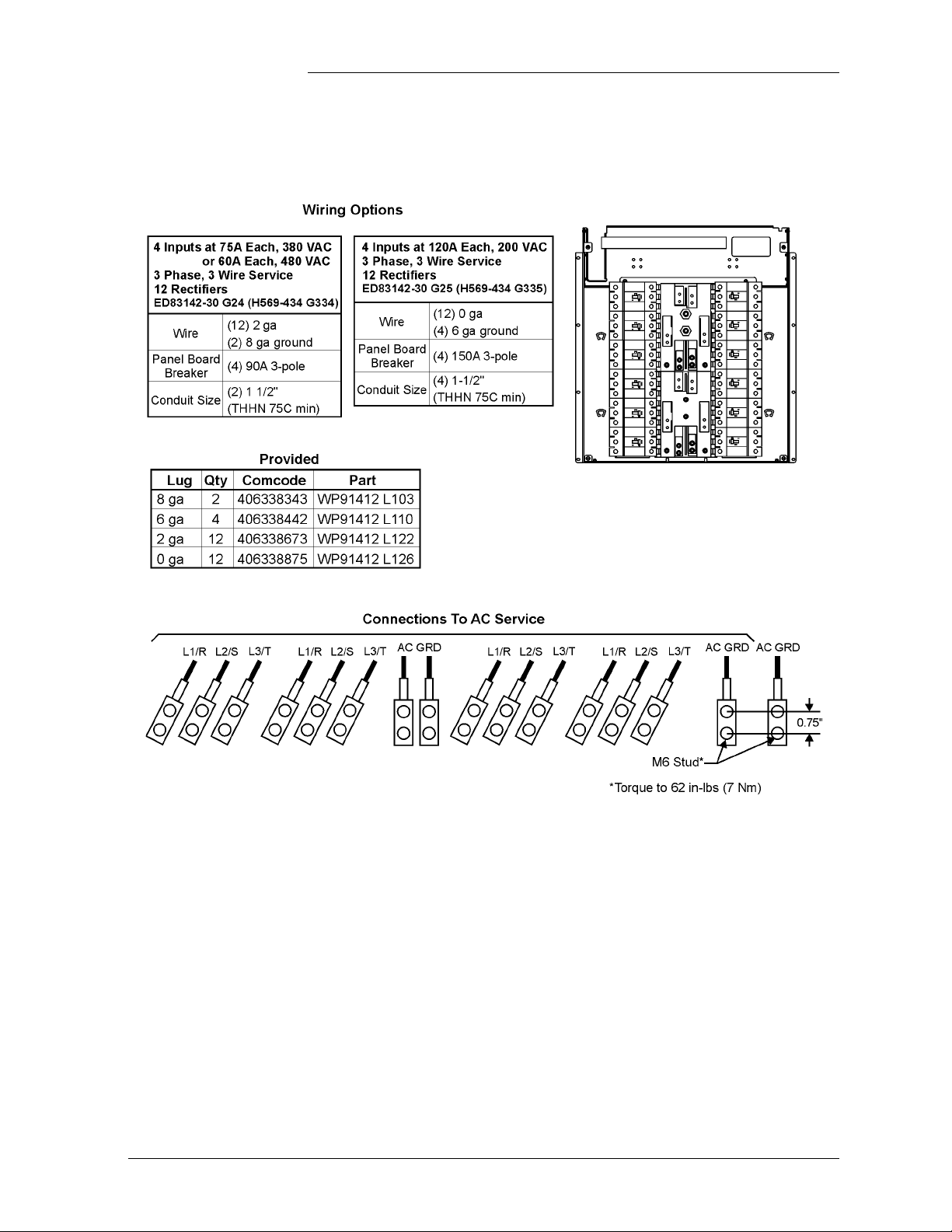
Installation Guide for Galaxy Power Systems
AC Input Panels, continued
Figure 7-7: ED83142-30 Group 24 or 25 (H569-434 G334, G335)
AC Input Panel for 595LTA or LTB Series Rectifiers
Issue 12 August 2012 AC Connection and Wiring 7 - 13
Page 98

Installation Guide for Galaxy Power Systems
AC Input Panels, continued
Figure 7-8: ED83142-30 Group 5
(H569-434 G24, G25, G26, G27, G224, G226, G324, G325, G326, G327, G425, G429)
AC Input Panel for 595A, B, or C (DA) Series Rectifiers
7 - 14 AC Connection and Wiring Issue 12 August 2012
Page 99

Installation Guide for Galaxy Power Systems
AC Input Panels, continued
Figure 7-9: ED83142-30 Groups 6/6M
(H569-436/H569-437 G71H, G73F, G74H, G74F)
AC Input Panel for 596A or B Series Rectifiers
Issue 12 August 2012 AC Connection and Wiring 7 - 15
Page 100

Installation Guide for Galaxy Power Systems
AC Input Panels, continued
Figure 7-10: ED83142-30 Group 7 (H569/436/H569-437 G72F)
AC Input Panel for 596A Series or 596B Series Rectifiers
7 - 16 AC Connection and Wiring Issue 12 August 2012
 Loading...