

Page 1

GE Energy
®
EntelliGuard
R
Circuit Breaker Retrofill
AKD-5 Installation Manual
General Electric AKD-5 Low Voltage Switchgear is a free-standing assembly of
metal-enclosed units of power circuit breakers and other auxiliary power circuit
protective devices. It may also be a part of a single-ended or double-ended load
center unit substation. It’s a draw-out breaker.
imagination at work
Page 2

1 EntelliGuard R Circuit Breaker Retrofill AKD-5 Installation Manual DEH-41547 02/12
Table of Contents
Preface .................................................................................................................................................................... 3
Hazards .................................................................................................................................................................................................. 3
Danger...............................................................................................................................................................................................3
Warning.............................................................................................................................................................................................4
Caution .............................................................................................................................................................................................. 4
Notice or Note................................................................................................................................................................................ 5
Warranty................................................................................................................................................................................................ 5
Trademarks and Patents................................................................................................................................................................ 5
Standards.............................................................................................................................................................................................. 5
Document Conventions.................................................................................................................................................................. 5
Related Publications......................................................................................................................................................................... 6
Service and Support......................................................................................................................................................................... 6
Estimated Time to Complete Tasks........................................................................................................................................... 6
Description............................................................................................................................................................. 6
Product Specs...................................................................................................................................................................................... 6
Weight (lbs)...................................................................................................................................................................................... 7
Views ..................................................................................................................................................................................................7
History and Types ................................................................................................................................................. 9
AKD........................................................................................................................................................................................................... 9
AKD-5—AK25/AK50........................................................................................................................................................................... 9
Unpack Retrofill Circuit Breaker......................................................................................................................... 9
Quality...................................................................................................................................................................................................11
Information Label ............................................................................................................................................................................11
Product and Catalog Serial Numbers ....................................................................................................................................11
Remove Circuit Breaker from Container ........................................................................................................ 11
Inspect ..................................................................................................................................................................................................11
Use Lifting Truck...............................................................................................................................................................................11
Store Circuit Breaker.......................................................................................................................................... 13
Check Before Installing ...................................................................................................................................... 14
Clean and Grease Breaker................................................................................................................................. 14
Customize Retrofill Secondary Wiring ............................................................................................................ 15
Modify AKD-5 Switchgear Compartment ....................................................................................................... 15
Page 3

2 EntelliGuard R Circuit Breaker Retrofill AKD-5 Installation Manual DEH-41547 02/12
Cut Power............................................................................................................................................................................................16
Rack Out Legacy Breaker.............................................................................................................................................................16
Empty Compartment—Legacy Breaker Removed ...........................................................................................................16
Check, Clean, Grease Compartment ......................................................................................................................................16
Install Position Switch Actuator—AK25 Breaker ........................................................................................... 17
Install Position Switch Actuator—AK50 Breaker ........................................................................................... 18
Racking-Lock Bracket—Initial Tasks................................................................................................................ 19
Install Cassette (Landed Wires)........................................................................................................................ 21
Install Lock Bracket ............................................................................................................................................ 23
Install AKD-5 Retrofill Breaker.......................................................................................................................... 25
Secondary Disconnects, Bullets................................................................................................................................................32
Wiring Diagram and Block Info (AK25)...................................................................................................................................33
AK25 Wiring Harness, B-Block (AK25/50) .............................................................................................................................35
Programmer Secondary Disconnect (Breaker Side—N/A) ............................................................................................37
AK25..................................................................................................................................................................................................37
Install Door Interlock System (Breaker Side).................................................................................................. 38
Neutral Disconnect Assembly (Breaker Side)................................................................................................. 38
Install AKD-5—Neutral Rogowski Current Transformer (CT)........................................................................................38
Remove Existing Iron Core Neutral CT Assembly .............................................................................................................39
Neutral CT assembly in Cable/Bus Compartment: ..........................................................................................................39
AKD-5—Neutral Sensor Packaging.................................................................................................................. 41
AKD-5—Multi-Source Ground Fault ................................................................................................................. 42
Remove and Replace AKD-5—Existing Door .................................................................................................. 43
Wiring Diagram for the AK/AKR Retrofill........................................................................................................ 44
Notes ..................................................................................................................................................................... 45
Page 4

3 EntelliGuard R Circuit Breaker Retrofill AKD-5 Installation Manual DEH-41547 02/12
Preface
Hazards
The following important highlighted information appears throughout this document to warn of potential
hazards or to call attention to information that clarifies a procedure. Carefully read all instructions and
become familiar with the devices before trying to install, operate, service, or maintain this equipment.
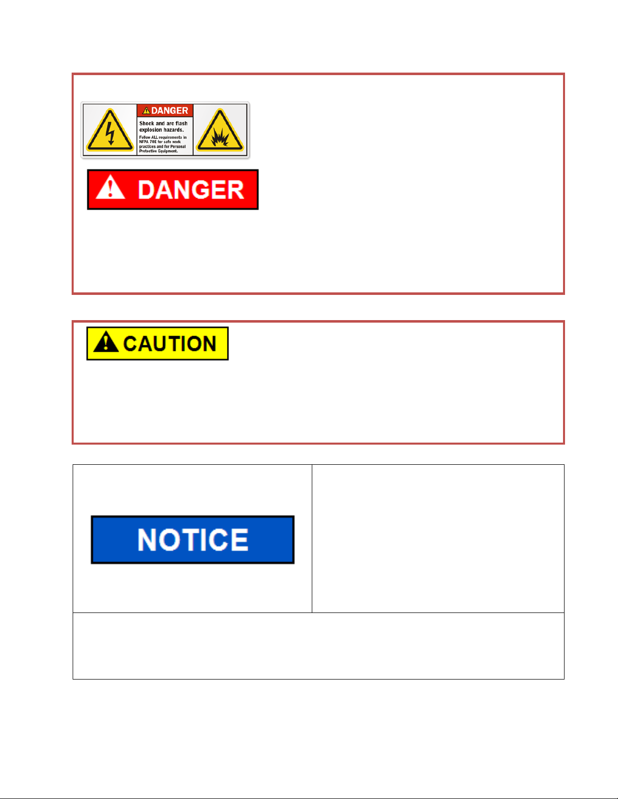
Danger
This indicates a hazardous situation which, if not avoided, results in death or serious injury. A variety
of electrical hazards warnings are displayed here and are applied to installation manuals. These are
standard or generic alerts and labels that must be taken quite seriously when installing Retrofill
circuit breakers in AKD switchgear and when working with potentially dangerous electrical equipment
(Table 1). There are also dangers, pertaining to product safety, that need to be custom-written for
particular or specific circumstances (Table 2).
Table 1. Generic Danger Alerts and Labels Used for Documentation and
Dangerous Equipment
Table 2. Custom Danger
Alerts and Labels Used for
Documentation and
Dangerous Equipment
Page 5
4 EntelliGuard R Circuit Breaker Retrofill AKD-5 Installation Manual DEH-41547 02/12
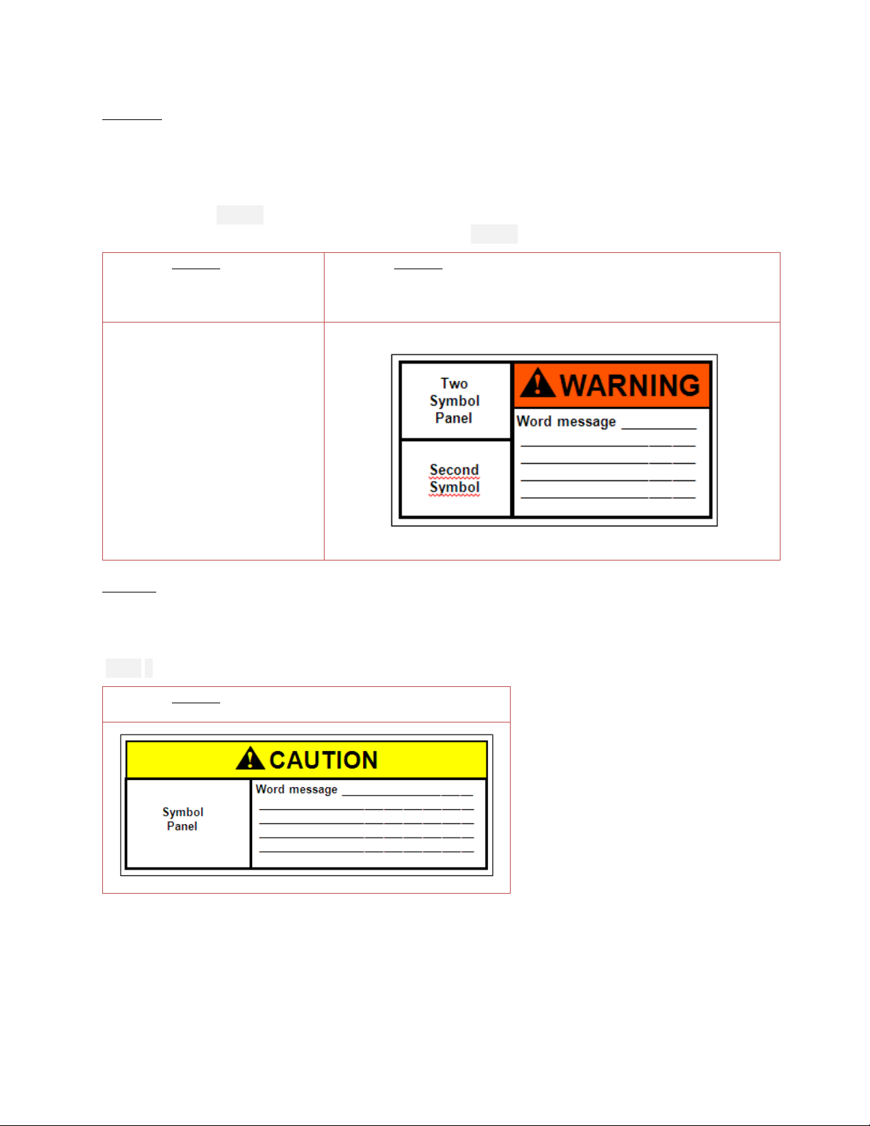
Warning
This indicates a hazardous situation, which, if not avoided, would result in death or serious injury. A
variety of electrical hazards warnings are displayed here and are applied to installation manuals. These
are standard or generic alerts and labels that must be taken quite seriously when installing Retrofill
circuit breakers in AKD switchgear and when working equipment that can cause injury, but may not be
necessarily fatal (Table 3). There are also warnings, pertaining to product safety, that need to be
custom-written for particular or specific circumstances (Table 4).
Table 3. Generic Warning
Alerts and Labels Used for
Documentation and Dangerous
Equipment
Table 4. Custom Warning Alerts and Labels Used for Documentation
and Dangerous Equipment
Caution
This pertains to a hazard that has a low level of risk, which means that if not avoided, it could result
in minor or moderate injury. It also indicates that failure to comply with instructions may result in
product damage. The label here requires a specific message that targets a special product or procedure
(Table 5).
Table 5. Custom Caution Alerts and Labels Used for
Documentation and Operating Equipment
Page 6
5 EntelliGuard R Circuit Breaker Retrofill AKD-5 Installation Manual DEH-41547 02/12
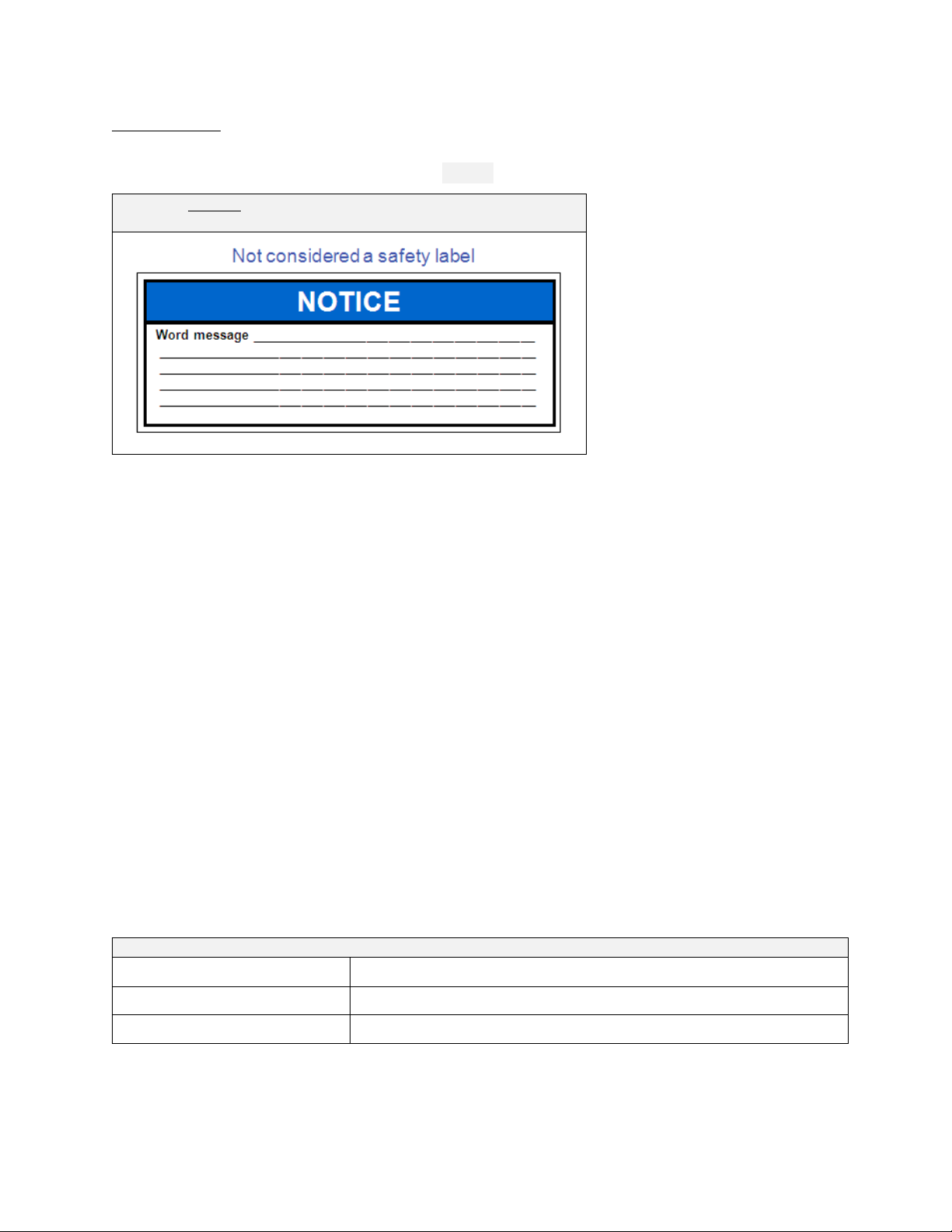
Notice or Note
This indicates important information in that it aids in job performance, that is, a notice or note is used to
notify practices not related to personal injury (Table 6).
Table 6. Custom Notice Alerts and Labels Used for
Documentation and Operating Equipment
Warranty
This document is based on information available at the time of its publication. While efforts have been
made to ensure accuracy, the information contained herein does not cover all details or variations in
hardware and software, not does it provide for every possible contingency in connection with
installation, operation, and maintenance.
Features may be described herein that are not present in all hardware and software systems. GE Energy
assumes no obligation of notice to holders of this document with respect to changes subsequently
made. GE Energy makes no representation or warranty, expressed, implied, or statutory, with respect to,
and assumes no responsibility for the accuracy, completeness, sufficiency, or usefulness of the
information contained here it. Not warrantees of merchantability or fitness for purpose shall apply.
Contact your local sales office if further information is required concerning any aspect of EntelliGuard R
Circuit breaker operation or maintenance.
Trademarks and Patents
EntelliGuard® R
EntelliGuard
®
TU
EntelliGuard
®
Trip Unit
EntelliGuard
®
G
Standards
Agency Certification
Standard Number
Title
ANSI C37.13,16,17,20,50,59
Low-Voltage AC Power Circuit Breakers
UL 1066
Low-Voltage AC and DC Power Circuit Breakers Used in Enclosures
Document Conventions
Topics and text are divided into primary, secondary, and tertiary paragraph headings.
Page 7

6 EntelliGuard R Circuit Breaker Retrofill AKD-5 Installation Manual DEH-41547 02/12
Related Publications
Publication
Publication Number
Brochure
DEA-532
Snapshot
DEE-543
Installation Manual AKD8
DEH-41549
Installation Manual AKD6
DEH-41548
Installation Manual AKD5
DEH-41547
Accessory: Door Interlock (Door Interlock Kit)
DEH-41529
Accessory Retrofill Doors Assembly
DEH-41563
Accessory: Position Switch Plate & Position Switch Assembly & Wiring (Position Switch Kit)
DEH-41530
Accessory: Neutral Rogowski CT Disconnect (Neutral Assemblies)
DEH-41531
Accessory: Programmer Disconnects
DEH-41532
Accessory: Finger Clusters (Cluster Assemblies)
DEH-41533
Accessory: Secondary Disconnects
DEH-41534
FAQ
DEQ-171
Application Guide
DET-753
Guideform Spec
DET-754
Spare/Renewal Parts Guide
DET-755
Service and Support
In addition to the local field sales office and service teams, GE also has a dedicated Aftermarket team to
assist customers with legacy information, selection, ordering, and upgrading.
Estimated Time to Complete Tasks
It takes about 20 minutes to install a feature-for-feature LSI assembly. This includes racking out the old
breaker, racking in the new breaker, and replacing the door. If new options are desired, or if it’s a 4-wire
LSIG circuit or modifications are needed to the cubicle, then additional time is required. Time also does
not include wiring the secondary disconnect on the retrofill.
Description
Product Specs
General Electric AKD-5 Low Voltage Switchgear is a free-standing assembly of metal-enclosed units
of power circuit breakers and other auxiliary power circuit protective devices. It may also be a part of
a single-ended or double-ended load center unit substation. It’s a draw-out breaker. Figure 1 shows
the retrofill circuit breaker projected out of its cassette. Figure 2 shows the AK25 retrofill breaker in
the cassette.
Page 8
7 EntelliGuard R Circuit Breaker Retrofill AKD-5 Installation Manual DEH-41547 02/12
Weight (lbs)
Retrofill Breaker
Weight
Box Weight 10101653P1
Pallet 10101650P1 Wt
Accessories
Wt
Total
Weight
AK25
197
16
33
2
248
Retrofill Breaker
Weight
Pb2 Large Frame Box Wt
10101653P1
Pallet 10101513P1 Wt
Accessories
Wt
Total
Weight
AK25
200
11
24
2
237
AK50
289
11
24
2
326
Retrofill Breaker
Weight
Box Weight 10101655P1
Pallet 10101650P1 Wt
Accessories
Wt
Total
Weight
AK50
289
18
33
2
342
Views
Figure 1. EntelliGuard R Retrofill (Circuit Breaker
Projected from Cassette)
Figure 2. EntelliGuard R AK25 Retrofill
(Front View)
A rear view of the AK25 is featured in Figure 3. Figure 4 shows the AK25 without its cassette.
Page 9

8 EntelliGuard R Circuit Breaker Retrofill AKD-5 Installation Manual DEH-41547 02/12
Figure 3. EntelliGuard R AKD-5—AK25 Retrofill
(Rear View)
Figure 4. AKD-5—AK25 Retrofill Breaker without
Cassette (Front View)
Figure 5 shows a rear view of the AKD-5—AK25 retrofill cassette, or substructure, without the breaker;
Figure 6 shows a front view of the cassette.
Figure 5. AKD-5—AK25 Retrofill Breaker Cassette
Assembly (Rear View)
Figure 6. AKD-5—AK25 Retrofill Breaker Cassette
Assembly (Front View)
The EntelliGuard R Circuit Breaker is suitable for application on power systems up to 600 VAC 50/60 Hz
systems and up to 600 Vdc as a main/source breaker, feeder breaker, bus coupler, or tie breaker.
Page 10

9 EntelliGuard R Circuit Breaker Retrofill AKD-5 Installation Manual DEH-41547 02/12
History and Types
AKD
AK—Power Circuit Breaker Equipment
D—Drawout circuit breaker construction
Manufactured from 1951 to 1975 were these: all bolted, copper bus design, all drawout breakers—AK-1,
—2, —3,—15 / 25 / 50 / 75 / 100; the 4000A-max bus rating, 4 levels of bus, ring-bus used in all feeder
sections, and the main bus with provisions for future extension; sections in outdoor construction, which
did not line up in the front; and indoor construction, with extended frames allowing the section fronts to
line up. Moreover, there were indoor depths: 49" (225 / 600A breakers), 59" (1600A breakers), and 63"
(3200 / 4000A breakers).
Back then, breakers had a ratcheting drawout mechanism, with an open-door drawout. Breakers were
painted ANSI 61, light gray, manufactured in Philadelphia from 1951 to the mid-60s and in Burlington
from the mid-60s to 1975.
The breaker compartment was a welded assembly, and the equipment frame was bolted. Breaker
boxes were stacked to make a vertical section with equipment frame around the breaker boxes. There
were no bus compartment barriers, just an open bus design. Ring silver-plating was applied to bolted
connections.
AKD-5—AK25/AK50
Manufactured from 1960 until 1977, the aluminum bus had copper that was “flash-butt welded” to the
aluminum at bolted connections. During that time, AK-2A, 3A -25 / 50 / T50 / 75 / 100 (“A” signifies AKD5 drawout) were produced. Pull-lanyard drawout mechanism on early design was replaced by a single
jackscrew mechanism and then later replaced by a double jack-screw mechanism. Featured is a closeddoor, drawout with inner house breaker compartment. There is a 60"-deep frame with the 18"-extension
option. Outdoor protected aisle uses 60"-deep indoor frame. Two bus levels are available with a ring bus
used at 4000A. Particulars include: welded/riveted frame, bus compartment barriers, line/load
separation barriers on mains and ties, isolation barriers on transformer transitions, copper runbacks on
feeder breakers, ring silver-plating on copper, and aluminum bus un-plated (welded connections). The
switchgear is painted sand-gray (beige), with some instrument doors painted blue. AKR-30/50 in 22"wide sections were introduced in AKD-5 construction, early 70s. AK25s and AK50s were also available
as substructure kits for OEMs to build around customer gear.
Unpack Retrofill Circuit Breaker
By following the procedures below, you should be able to install the breaker with minimum effort
and time.
Page 11
10 EntelliGuard R Circuit Breaker Retrofill AKD-5 Installation Manual DEH-41547 02/12
Turn off all power to switchgear. Tagout and
lockout main source, up-stream or main
breaker.
Failure to comply with these instructions will
result in death or serious injury from severe
burns caused by arc flashing that has
exceedingly high temperatures.
Always wear personal protection equipment
according to OSHA standards and appropriate
to the severity of potential burns.
• Ensure only qualified personnel install, operate, service, and maintain all electrical
equipment.
Falling Object
• Do not walk or remain under any heavy assembly while
hoisted above head as the chains securing the
assembly may give way
• Ensure lifting equipment has capability for device being lifted.
• Wear hard hat, gloves, and safety shoes.
• Failure to comply with these instructions could result in serious injury.
PRODUCT DAMAGE
• Ensure circuit breaker and its accessories
are always used within their designated
ratings.
• Do not allow the circuit breaker to hit a
hard surface while handling.
• Do not drag or slide the circuit breaker
across a hard or rough surface
• A factory-installed rejection feature prevents mismatching circuit breakers and
cassettes/substructure, preventing the insertion of a circuit breaker with a lower rating into a
higher rated cassette/substructure, or the insertion of a higher rated circuit breaker into a lower
rated cassette/substructure.
Page 12

11 EntelliGuard R Circuit Breaker Retrofill AKD-5 Installation Manual DEH-41547 02/12
Quality
All EntelliGuard R circuit breakers have been designed and manufactured to ANSI standards. The design
was based on the original requirements from the Legacy Switchgear and Breaker. The product is
manufactured in the same factory as the AK and AKR; and is inspected using the same master gauges
used on the legacy AK, AKR breakers to confirm electrical and mechanical performance, including
rejections-features.
Information Label
On the side wall of each circuit breaker there is a detailed factory-assembled, side label that details all
features included on both the circuit breaker and on the trip unit.
Product and Catalog Serial Numbers
Product and catalog serial numbers should be kept handy when communicating about the circuit
breaker. Each circuit breaker has a unique serial number located on the left side (viewed from front) of
the front fascia.
Remove Circuit Breaker from Container
Inspect
1. Inspect the shipping container for obvious signs of rough handling and/or external damage incurred
during transportation.
2. Record any observed damage for reporting to the carrier. Ensure all recorded reports and claims
include the order number and name plate information.
3. Remove the banding straps and lift off the top cover.
4. Remove all packaging material.
5. Remove all product documentation and store properly.
6. Unscrew the mounting screws that fasten the circuit breaker to the bottom of the shipping palette
and remove the circuit breaker.
Use Lifting Truck
1. Use a lifting truck to lift and mount the assembly so that you can avoid personal injury or damaging
the breaker.
2. Contact the nearest sales office for availability of a hoisting device.
3. Avoid using hooks and chains since hooks can damage the fascia of the circuit breaker. Lifting bars
are available from GE.
• AK breakers use the EntelliGuard G lifting device.
• AKR breakers use the legacy lifting bar.
4. Pull out the ears of the AKD—5 so that the bar can be inserted through the ears for hoisting breaker
(Figure 7).
Page 13
12 EntelliGuard R Circuit Breaker Retrofill AKD-5 Installation Manual DEH-41547 02/12
Figure 7. AKD-5—Breaker Lifting Holes
5. Avoid using hooks and chains since hooks can damage or bend the “ears” as well damage the
fascia. Below are two examples of how not to handle the breaker (Figure 8 and Figure 9).
Figure 8. Crane Lifting Hooks Can Damage Lifting Holes
and Ears
Figure 9. Chains Can Damage Fascia
Page 14

13 EntelliGuard R Circuit Breaker Retrofill AKD-5 Installation Manual DEH-41547 02/12
Store Circuit Breaker
If you decide not to install the retrofill breaker until a later time, then you can store it away for
installing later.
PRODUCT DAMAGE
environments above LC1 (sea salt mist)
and G1 as per ANSI/ISA-S71.04-1985.
• Ensure circuit breakers and cassettes are
stored in a clean, dry location, in their
original packaging.
• Failure to comply with these instructions
may result in product damage.
1. Store the circuit breakers in a clean, dry location in an upright position.
2. Make sure that the breakers are properly supported to prevent bending of the studs or damaging
any of the breaker parts. Do not remove any protective grease until the breaker is ready to be
installed. A covering of draft or other non-absorbent paper prevents dust from settling on the
breakers.
3. If breakers are not to be placed in service immediately, remove them from their shipping cartons
and thoroughly inspect them.
4. If everything is in satisfactory condition, replace the breakers in their shipping cartons for storage.
Do not move the shipping members at this time.
If it is necessary to store the equipment for any length of time, follow these precautions to prevent
corrosion or deterioration.
5. Uncrate the equipment and check thoroughly for damage.
6. Store in a clean, dry, rodent-free location with moderate temperature and provide protective
coverings to prevent dirt, water, or other foreign substances from entering the breaker.
7. If dampness or condensation is encountered in the storage location, heaters for circuit breakers in a
closed environment can be used to prevent moisture damage.
Page 15

14 EntelliGuard R Circuit Breaker Retrofill AKD-5 Installation Manual DEH-41547 02/12
Check Before Installing
• It must be ensured that the supply power to
the compartment is turned off/ compartment
is de-energized for all the incoming and
outgoing circuits of the LVS prior to any work
being conducted on it.
• During the installation and related work on
the equipment, it must be ensured that the
operator is using the prescribed PPE for the
specified tasks.
• Ensure only qualified personnel install, operate, service, and maintain all electrical
equipment.
These breakers are supported on a rollout track in the same manner as the AKR breakers. However,
since the rack-out mechanism is mounted on the breaker, there are no jack-screws in the enclosure.
Racking arms on both sides of the breaker frame engage the drawout mechanism pins that are
fastened to both sides of the compartment.
1. Check to see that the breaker or breakers match their respective compartments. Each breaker is
assigned a part or mark number.
2. Read the breaker sheets summaries, the front view drawings, breaker nameplate, and the
identification card on the breaker shipping carton.
3. To match the breaker to its proper compartment, refer to the breaker location list on the front view
drawing. Find the proper breaker by the identification card on the breaker carton, or the mark
number on the breaker nameplate. All identical breakers have the same mark numbers.
4. For retrofills replacing AK25 breakers, if applicable, the neutral disconnect assembly block and
bracket within the compartment must be removed. Removing this item should be done only after
the breaker, having been removed from the compartment, has been de-energized.
Clean and Grease Breaker
1. Before installing or operating a breaker, refer to the EntelliGuard G Breaker DEH-41304 instruction
manual for pre-operation inspecting and testing.
2. Check thoroughly for any damaged or loose parts and for any dirt or foreign matter which may be in
the breaker.
3. Clean those areas if necessary with a clean, lint-free rag and isopropyl alcohol or acetone.
4. Be sure to apply a thin film of electrical grease (red, D50H47) to the contact areas for better
electrical connections on the breaker.
Page 16

15 EntelliGuard R Circuit Breaker Retrofill AKD-5 Installation Manual DEH-41547 02/12
Customize Retrofill Secondary Wiring
WIRING
• Before installing the breaker, the
secondary disconnects must be wired to
the EntelliGuard Breaker.
• Wires with wire markers are provided on
the retrofill. Make sure that the
switchgear wiring connection points
match up with the original wiring of the
cubicle. This ensures that all wiring
connections are properly made.
• Wrong connections will cause the breaker
to malfunction.
Modify AKD-5 Switchgear Compartment
• It must be ensured that the supply power
to the compartment is turned off/
compartment is de-energized for all the
incoming and outgoing circuits of the LVS
prior to any work being conducted on it.
• During the installation and related work on
the equipment, it must be ensured that the
operator is using the prescribed PPE for the
specified tasks.
• Ensure only qualified personnel install, operate, service, and maintain all electrical
equipment.
Page 17

16 EntelliGuard R Circuit Breaker Retrofill AKD-5 Installation Manual DEH-41547 02/12
Cut Power
1. Before modifying the switchgear compartment, de-energize/switch off the breaker. If the circuit
breaker is ON and the springs are charged, to turn it off, press the OPEN button on the circuit
breaker fascia; and ensure that the circuit breaker contacts are open.
Rack Out Legacy Breaker
1. To rack-out legacy (old or original) breaker from the compartment, refer to your legacy-breaker’s
manual on how to remove the existing breaker.
Empty Compartment—Legacy Breaker Removed
The following examples show a legacy breaker removed from the enclosure or compartment (Figure 10).
Figure 10. AKD-5—Empty Cubicle
Check, Clean, Grease Compartment
1. Inspect the compartment for damage, rework.
2. Check cabinet for suitability of retrofill.
3. Check each breaker compartment for bolted joints in the primary disconnect bars. Where such
joints exist, check the bolts for tightness.
Page 18

17 EntelliGuard R Circuit Breaker Retrofill AKD-5 Installation Manual DEH-41547 02/12
4. Inside the compartment, check the contact areas on each primary disconnect bar or cluster of
fingers for foreign matter that may have accumulated. Clean those areas if necessary with a clean,
lint-free rag and isopropyl alcohol or acetone.
5. Be sure to apply a thin film of electrical grease (red, D50H47) to the contact areas for better
electrical connections inside the compartment.
After removing the existing breaker from the compartment, you now need to install the AKD-5 cassette
in the AKD-5 compartment or enclosure.
Install Position Switch Actuator—AK25 Breaker
Installing the position switch actuator needs to be done before the cassette is racked into the
compartment. Steps of installation of the position switch actuator are as follows.
1. Place the retrofit EntelliGuard ACB cassette assembly for AK25 on an elevated surface, such as a
table, mounting the position switch actuator assembly on to the base plate.
Sufficient space should be available at the bottom of the cassette and the mounting table so as to
provide easy access for inserting the 3-pin bracket from the bottom.
2. Unpack the position switch actuator assembly and mount it as shown in the exploded view
(Figure 11).
Figure 11. Position Switch Actuator Assembly
3. Insert the 3-pin bracket from the bottom of the base of the cassette assembly such that the 2 pins
are within the longer slot and the single pin goes inside the smaller slot of the plate.
4. Place the L-bracket from the top of the cassette assembly such that the pins from the bottom 3
pin plate get inserted into the top plate.
5. Secure the connecting by fastening the nuts provided in the actuator kit along with the washers.
Page 19

18 EntelliGuard R Circuit Breaker Retrofill AKD-5 Installation Manual DEH-41547 02/12
6. Mount the extension springs between the groove of the pin on this actuator assembly and the
fixed pin provided on the cassette base plate.
Note that the position switch actuator on the cassette is now installed and ready for use once the
breaker is being racked into the compartment.
7. Mount the cassette assembly on the rails of the AK25 cabinet in the AKD-5 and rack the cassette
into the compartment of the AKD-5 LVS.
Note: During racking of the EntelliGuard ACB breaker into the cassette during racking in of the breaker,
the position indicator window reads “connected.” This is the position that corresponds to the point when
the retrofit system has activated the existing position switch in the LVS.
Install Position Switch Actuator—AK50 Breaker
Figure 12. AKD-5—AK50, Actuator for Position Switch
Assembly (Exploded View)
The position switch actuator assembly for
the AK50 should be mounted on the
bottom right side of the cassette
assembly of the AK50 retrofill. The
actuator assembly consists of a linkage
system that interfaces with the racking
shaft assembly at one end and the
position switch actuator arm on the other.
Completing the racking in of the
EntelliGuard breaker into the cassette
corresponds to the end of stroke of the
position switch system in the
compartment for AK50 in AKD-5 LVS.
Figure 12 shows the AK50 position switch
actuator assembly in an exploded view.
The position switch actuator of the AK50
is a field-fit type of assembly and is
assembled on the retrofill cassette before
insertion of the cassette into the
compartment of the AKD-5.
8. Make sure that the cassette is in the disconnected state.
This can be verified by checking the racking position status on the window located at the right side
window on the frame of the AK50 Retrofill cassette, placed at the front. The position switch
actuator kit of the AKD5—AK50 retrofits must be installed on the rear side, right-side sheet of the
AK50 retrofit cassette.
Page 20

19 EntelliGuard R Circuit Breaker Retrofill AKD-5 Installation Manual DEH-41547 02/12
9. Place the cassette on a work table.
The cassette should be positioned such that there is enough overhang of its side so that you can
insert the position switch actuator assembly in the bottom of the cassette. Alternately, the
installation can also be done by placing the cassette assembly on the retrofit AK50 while it is on
the telescopic rails of the AKD5 compartment, being retrofitted.
10. As soon as the position switch actuator is installed, slide the assembly up from the bottom of the
cassette. When inserted, flip the position switch.
11. Line up the holes on the cassette side sheet with the holes provided on the actuator assembly.
12. Fasten the 3 M6 bolts and 6mm washers provided with the actuator assembly to the three holes
on the cassette side sheet. Two holes are placed on the side and one hole on the rear of the
cassette assembly.
The position switch actuator on the cassette is now installed and ready to be activated as soon as
the breaker is racked into the compartment.
13. Mount the cassette assembly on the rails of the AK25 cabinet in the AKD-5 and rack the cassette
into the compartment of the AKD-5 LVS.
Note: As the EntelliGuard ACB breaker is racked in the cassette, the position indicator window reads
“connected”. This indicates that the retrofit system has activated the position switch in the LVS.
Racking-Lock Bracket—Initial Tasks
• It must be ensured that the supply power
to the compartment is turned off/
compartment is de-energized for all the
incoming and outgoing circuits of the LVS
prior to any work being conducted on it.
• During the installation and related work on
the equipment, it must be ensured that the
operator is using the prescribed PPE for the
specified tasks.
• Ensure only qualified personnel install, operate, service, and maintain all electrical
equipment.
1. Remove existing indicator assembly system from AKD-5 cabinet rails (Figure 13).
2. Clean the area of the moving frame assembly of any dirt or debris.
3. Unpack the racking lock kit for the AKD-5.
4. Use this bracket as a template for drilling the holes in the frame (Figure 14).
Page 21

20 EntelliGuard R Circuit Breaker Retrofill AKD-5 Installation Manual DEH-41547 02/12
Figure 13. Legacy Indicator Assembly
Figure 14. Bracket Template for
Drilling Holes
5. Slide the bracket (Figure 14) up to its fixing location as shown in the illustration (Figure 15).
6. Line up the guiding holes (Figure 16).
Figure 15. Slide Bracket Up
Figure 16. Line Up Holes
7. Mark the bottom two holes using the bracket as a template.
8. Take the bracket out and drill 0.18-in diameter pilot holes in the frame.
Page 22

21 EntelliGuard R Circuit Breaker Retrofill AKD-5 Installation Manual DEH-41547 02/12
Install Cassette (Landed Wires)
• It must be ensured that the supply power to
the compartment is turned off/
compartment is de-energized for all the
incoming and outgoing circuits of the LVS
prior to any work being conducted on it.
• During the installation and related work on
the equipment, it must be ensured that the
operator is using the prescribed PPE for the
specified tasks.
• Ensure only qualified personnel install, operate, service, and maintain all electrical
equipment.
The photo in View 1 of Figure 17 shows the rear view of the wires landed on the AKD-5 cassette; View 2
shows the front view of the AKD-5 cassette, ready for installation.
Figure 17. AKD-5—Cassette, View 1
AKD-5—Cassette, View 2
1. Install the pre-wired cassette in the enclosure as demonstrated in the photos, below.
2. Place the cassette on the rails for racking into the switchgear cabinet (Figure 18).
3. Slide the retrofit cassette into the compartment till dead-stop.
4. Lock the rails of the legacy compartment to ensure inner and outer rail movement.
5. Use legacy (old or original) AKR racking handle for inserting the retrofit cassette.
6. Fix legacy (old or original) racker-lock on the compartment side frame to block slide back of sleeve.
The following photos show how the cassette is racked in and secured (Figure 19), rails extended
(Figure 20), left side view; and (Figure 21), racking in.
Page 23

22 EntelliGuard R Circuit Breaker Retrofill AKD-5 Installation Manual DEH-41547 02/12
Figure 18. AKD-5—Cassette To Be Racked In, View 1
AKD-5—Cassette To Be Racked In, View 2
Figure 19. AKD-5—Cassette or
Substructure, Rails Extended
Figure 20. AKD-5—Cassette or
Substructure, Left Side Details
Figure 21. AKD-5—Cassette or
Substructure, Racking and
Removing Tool, View 1
The next two figures (Figure 22 and Figure 23) display the complete racking in of the pre-wired cassette.
Page 24

23 EntelliGuard R Circuit Breaker Retrofill AKD-5 Installation Manual DEH-41547 02/12
Figure 22. AKD-5—Cassette or Substructure, Racking and
Removing Tool
Figure 23. AKD-5—Cassette or
Substructure, Now Racked In
Install Lock Bracket
• It must be ensured that the supply power
to the compartment is turned off/
compartment is de-energized for all the
incoming and outgoing circuits of the LVS
prior to any work being conducted on it.
• During the installation and related work on
the equipment, it must be ensured that the
operator is using the prescribed PPE for the
specified tasks.
• Ensure only qualified personnel install, operate, service, and maintain all electrical
equipment.
1. Check that the retrofitted EntelliGuard cassette has been completely racked into the cabinet.
2. Slide the bracket back into position as shown in the image below (Figure 24) and line up the holes
previously drilled with the holes on the locking bracket (Figure 25).
Page 25

24 EntelliGuard R Circuit Breaker Retrofill AKD-5 Installation Manual DEH-41547 02/12
Figure 24. Position Bracket
Figure 25. Line Up Bracket
3. Secure the bracket to the side frame by using the two self-tapping screws provided with the kit
(Figure 26 and Figure 27).
Tools required: Spanner, 0.2-inch drill bit, hand drill
Figure 26. Installed Bracket (View 1)
Figure 27. Installed Bracket (View 2)
Page 26

25 EntelliGuard R Circuit Breaker Retrofill AKD-5 Installation Manual DEH-41547 02/12
Install AKD-5 Retrofill Breaker
• It must be ensured that the supply power
to the compartment is turned off/
compartment is de-energized for all the
incoming and outgoing circuits of the LVS
prior to any work being conducted on it.
• During the installation and related work on
the equipment, it must be ensured that the
operator is using the prescribed PPE for the
specified tasks.
• Ensure only qualified personnel install, operate, service, and maintain all electrical
equipment.
1. Before inserting the retrofit breaker into the cabinet, make sure that the breaker is switched off. If
the spring indicator shows that it is charged, the assembly needs to be discharged, by first switching
on the breaker and then switching it off.
2. After you racked in the cassette, get ready to install the AKD-5 breaker assembly by pulling the
lifting hooks up (lifting handles, eyes, or ears) from their slots. Use a tool or screwdriver to keep them
up, if necessary (Figure 28).
Figure 28. AKD-5—Breaker Lifting Holes
3. Get a hand-crane and wheel it over to the breaker.
4. Lower the boom of the lifting device so that you have enough slack to insert its two hooks in the
breaker lifting holes (Figure 28). Or attach a lifting bar between the two holes eyes of the circuit
breaker, instead of hooks.
5. Make sure that the crane lifting hooks are secured and locked in placed on the breaker.
6. Using the hydraulic lift, raise the breaker slowly so that it clears the breaker platform. Suspend the
hoisted breaker a yard off the ground or floor. Carefully wheel the crane with the hoisted breaker
over to the switchgear for installation (Figure 29).
7. Put the breaker in front of the unit where it is to be installed, leaving enough clearance to swing the
compartment door open to access the enclosure.
Page 27

26 EntelliGuard R Circuit Breaker Retrofill AKD-5 Installation Manual DEH-41547 02/12
8. When the breaker is lined up with the compartment, raise the breaker only slightly higher than the
compartment floor, keeping it at slight angle.
9. Open the compartment door, if not already opened, to install the breaker in the cassette, (Figure 30).
Figure 29. Cabinet with Compartment
Door Closed
Figure 30. Cabinet with Compartment
Door Open
10. After you open the compartment door, check that the cassette is free from obstruction. Figure 30
displays the racking assembly, supporting the new retrofill breaker.
11. Remove any padlocks and keep the key in place for key locks if applied from the racking panel of
the cassette.
12. Verify that the cassette position indicator shows DISCONNECTED and the racking handle is
disengaged.
13. Ensure that the cassette racking cams on both side walls of the cassette are in the completely
racked-out position as shown in Figure 31.
14. Pull out the two racking arms (or loading/cassette rails) to their full extent, horizontal to the ground
(Figure 31).
Page 28

27 EntelliGuard R Circuit Breaker Retrofill AKD-5 Installation Manual DEH-41547 02/12
Figure 31. Racking Arms / Loading Rails, Extended
15. Lower the circuit gradually, at an angle, so that the rollers drop over the rails. Make sure that the
grooves in all rollers straddle the rails as shown in Figure 32.
This might need a two-man effort: one to carefully and slowly lower the boom with the suspended
breaker and the other to guide the breaker into the cassette enclosure. See Figure 32. You might
have to jockey the circuit breaker into position to align wheels with the rails.
Figure 32. Inserting Breaker into Cassette, Wheels Lined Up with Roller Arms
16. Keep the breaker steady. Continue to guide the breaker, while checking both sides and underneath
the assembly, so that both sets of wheels can be lowered easily on the cassette rails (Figure 33).
Check that the grooves in all rollers straddle the rails.
Page 29

28 EntelliGuard R Circuit Breaker Retrofill AKD-5 Installation Manual DEH-41547 02/12
Figure 33. Keeping Breaker Steady
17. Peer underneath the breaker, as you maneuver it in, to make sure that the dual blades clear the
bottom of cassette. See Figure 34.
Figure 34. View of Underside of Breaker
18. As soon as the breaker is resting on the rails Figure 35, unhook the lift from the ears of the circuit
breaker and move the hoisting apparatus out of the way.
Page 30

29 EntelliGuard R Circuit Breaker Retrofill AKD-5 Installation Manual DEH-41547 02/12
Figure 35. Breaker Positioned on Rails
19. Using the hand grips on either side, move or push the circuit breaker into the cassette until it
reaches a positive stop (the rollers on circuit breaker are engaged with the racking cams of the
cassette on both sides). Or, from the front, shove the breaker in as far as it can go.
The circuit breaker is now in the DISCONNECTED position (Figure 36).
20. Push back both the extended rails of the cassette to the stowed position.
21. If the circuit breaker is ON and the springs are charged, to turn the breaker off, press the OPEN
button on the circuit breaker fascia and ensure the circuit breaker contacts are open.
Figure 36. Breaker Ready for Complete Installation
Page 31

30 EntelliGuard R Circuit Breaker Retrofill AKD-5 Installation Manual DEH-41547 02/12
22. Remove the racking tool (Figure 37) from the storage location on the cassette front panel by
grabbing the handle.
23. Pull out the torque bar from inside the handle and extend the device.
Figure 37. Racking Tool
24. Figure 38 shows the racking assembly without breaker inserted.
Figure 38. Racking Assembly Inside Switchgear Compartment (w/no breaker)
25. Take a screwdriver, insert it in the slot or rack-out lock, and turn it clockwise 45° so that the racking
handle shutter, inside and behind the racking hole, moves to the right. (It resembles a vehicle
ignition lock. See Figure 39.)
Page 32

31 EntelliGuard R Circuit Breaker Retrofill AKD-5 Installation Manual DEH-41547 02/12
Figure 39. Shutter
26. After turning an eight of a turn and the shutter slides to the, remove the screwdriver, and insert the
racking tool in the hole (handle insertion hole). It’s located to the left of the racket lock (Figure 39).
27. Insert the tool so it that grabs or engages the racking mechanism inside the hole.
28. Line up the racking tool or crank with the handle straight up so that you can get some good
leverage or torque (Figure 40). Then, crank clockwise so that the cassette or substructure starts to
move in, slowly sliding forward.
Rotating clockwise racks the circuit breaker all the way into the cassette or substructure.
Figure 40. Crank or Racking Handle Inserted
29. As the breaker approaches the TEST position, check the alignment of the fixed and moving parts
of the secondary circuit isolating contacts.
Page 33

32 EntelliGuard R Circuit Breaker Retrofill AKD-5 Installation Manual DEH-41547 02/12
30. Continue rotating the racking handle clockwise until the position indicator first shows TEST,
then CONNECTED.
When approaching the CONNECTED position, effort to turn the racking handle increases as the
clusters engage with the cassette-mounted contacts. If a motor-spring charge or under-voltage-torelease is installed, the device may operate when approaching the TEST position.
31. Keep cranking as required, that is, when any further torqueing can’t be done.
At this point, the fingers at the back of the circuit breaker have completely grabbed onto the
contacts at the back of the cassette.
32. Remove and store the racking handle in it storage location.
It is a good idea to keep the racking handle always in the same place for future use.
33. Note that the circuit breaker is now ready for normal operation.
Secondary Disconnects, Bullets
The circuit breaker secondary disconnects are already located on, or wired to, the breaker’s cassette.
The landing of the wiring on the EntelliGuard R breaker cassette is done in the field. Up to 78 points are
available so that all breaker accessories can be wired to dedicated
disconnect-points in the cubicle.
Each breaker wire is identified with a unique label. The wireframes in Figure 41 and Figure 42 depict the
secondary disconnect assemblies for the AKD-5 AK25/AK50. Figure 43 shows the exploded view of four
blocks of secondary disconnects. The cassette is a separate assembly from the retrofill breaker; first, the
cassette is to be wired and then installed in the switchgear, the followed by the breaker being racked
into the cassette.
Figure 41. AK25 Retrofill Breaker
Cassette Assembly (Rear View)
Figure 42. AK25 Retrofill
Breaker Cassette Assembly
(Front View)
Figure 43. AK25 Retrofill
Breaker Cassette Assembly
(Exploded View)
P/N 386A110G2
Retrofill Sec Disc Assy AKR
AKD5
Page 34

33 EntelliGuard R Circuit Breaker Retrofill AKD-5 Installation Manual DEH-41547 02/12
The wiring harness for the secondary disconnects, located on the AKD-5 retrofill cassette, has 21 wire
connections (grouped in three blocks (A, B, C)) for AK50 or 28 wire connections (grouped in 4 blocks (A, B,
C, D)) for AK25, with seven wire connections for each block). Each wire is clearly labeled, or identified,
with wire markers or tags. Each wire on the 21-wire harness is connected to a bullet. Each bullet, when
the cassette is racked in, engages with its respective points in the switchgear. The wires for Block A are
identified as A1, A2,…A7. Block B wiring is likewise labeled as B1, B2, B3,….B7. Block C contains C1,
C2,….C7. The end, opposite of the bullets, maps or connects to the retrofill EntelliGuard R Cassette
78-point, secondary-disconnect. For example, if bullets A1 and A4 are reserved for the motor, they
connect to points A1 and A2 on the cassette’s 78-point, secondary-disconnect for a motor. Each breaker
needs to be landed in the field based on the specifics breakers wiring diagram and modifications made
in the field.
Figure 44 is a photo of the AKD-5—AK25 harness and Figure 45 is an AKD-5—AK25 C-block photo.
Figure 44. AK25 Harness, Top View
Figure 45. AK25 C-Block Harness
Wiring Diagram and Block Info (AK25)
Additional wire markers, cable ties, spade terminals, and sticky pads are provided. Refer to the AK wiring
scheme (Figure 46) and land the wires on EG-fixed secondary-disconnects. Wires are cut to size and
crimped with the terminal lugs, and provided with wire markers. Harness by cable ties is completed and
overhanging wires are checked. Similar to the AKD-5 AK25, the AKD-5 AK50 breaker roll-in replacement
uses a similar wire harness and is mounted on the cassette. For further information on blocks and
secondary-disconnects see Wiring Diagram for the AK/AKR Retrofill on Page44.
1. Get these tools needed for the task: Philips head screw driver, wire strippers, wire crimps, tie-wraps.
2. Identify each bullet using the legacy wiring diagram and any changes that were made to the legacy
compartment. Four-wire ground fault CTs are wired through a dedicated neutral disconnect vs. the
secondary bullets.
Page 35

34 EntelliGuard R Circuit Breaker Retrofill AKD-5 Installation Manual DEH-41547 02/12
3. With each bullet identified, land the non-bullet side to the corresponding feature on the
EntelliGuard R’s 78-point secondary disconnects. (See Wiring Diagram for the AK/AKR Retrofill on
Page 44.)
If a wire is too long, cut the wire, crimp a new connector, and install the provided wire markers on the
bullets. Refer to Wiring Diagram for the AK/AKR Retrofill, Page 44.
Figure 46. Example Wiring Diagram for AK25 Secondary Disconnects and Photo Example
Below are tables (Table 7 and Table 8) featuring the two 39-blocks (A and B). They make up the 78-point
secondary-disconnects.
Page 36

35 EntelliGuard R Circuit Breaker Retrofill AKD-5 Installation Manual DEH-41547 02/12
Table 7. EntelliGuard G 39-Point Secondary A-Block.
Table 8. EntelliGuard G 39-Point Secondary B-Block.
AK25 Wiring Harness, B-Block (AK25/50)
Photo in Figure 47 shows you the B-block harness and Figure 48 is a close-up photo of the harness.
Figure 49 shows you the secondary bullets.
Page 37

36 EntelliGuard R Circuit Breaker Retrofill AKD-5 Installation Manual DEH-41547 02/12
Figure 47. AK25 B-Block Harness
Figure 48. AK25 Wiring Harness, Close Up
Figure 49. Wires from Secondary Bullets
Page 38

37 EntelliGuard R Circuit Breaker Retrofill AKD-5 Installation Manual DEH-41547 02/12
Programmer Secondary Disconnect (Breaker Side—N/A)
Programmer secondary disconnects are not provided on AKD5 legacy LVS breakers. If the customer
chooses to use the advanced features of the EntelliGuard ACB, the control wiring needs to be routed
from the LVS directly to the secondary disconnect landing points on the cassette assembly of the
EntelliGuard ACB cassette. Refer to the tables (Table 7 and Table 8) featuring the two 39-blocks (A and B)
that make up the 78-point secondary-disconnects. Ordering info given here:
Install Position Switch Actuator (Breaker Side)
Legacy Breaker
Kit Number
AK50
10106296G1
AK25
10106269G1
AK25
The position-switch actuator assembly for the AK25 should be mounted on the bottom plate of the
cassette assembly of the AK25 retrofill. The actual actuator assembly consists of two plates, one on the
top (top plate) and one on the bottom of the baseplate. The top plate of the actuator interfaces with the
breaker when it is racked in and the motion of the same is transferred to the bottom plate which
interfaces with the position switch lever on the legacy compartment.
Completing the racking in of the EntelliGuard breaker into the cassette corresponds to the end of stroke
of the position switch system in the compartment for AK25 in AKD-5 LVS. Figure 50 shows the exploded
view of the AK25 retrofill position-switch actuator (actually a bracket assembly); Figure 51 displays the
assembly from the bottom.
Figure 50. AKD-5—AK25 Retrofill Breaker, Actuator
for Position Switch Assembly (Exploded View)
Figure 51. AKD-5—AK25 Retrofill Breaker,
Actuator for Position Switch Assembly
(Bottom View)
Page 39

38 EntelliGuard R Circuit Breaker Retrofill AKD-5 Installation Manual DEH-41547 02/12
Install Door Interlock System (Breaker Side)
Figure 52 shows the components that make up the AKD-5 retrofill door interlocking assembly:
Figure 52. AKD-5—Door Interlocking Components
For the retrofit, instructions for installing the interlocking system on the AKD-5 switchgear are the same
as those for EntelliGuard G Circuit Breaker. Refer to the Installation, Operation, and Maintenance Manual
for the EntelliGuard G Circuit Breaker, DEH-41304, 02 Apr 09.
Neutral Disconnect Assembly (Breaker Side)
When a legacy AK breaker is replaced with a retrofitted EntelliGuard ACB, the incoming wires from the
neutral CTs need to be routed to the cassette secondary-disconnects directly.
Install AKD-5—Neutral Rogowski Current Transformer (CT)
The AKD-5 EntelliGuard R Circuit Breaker uses an open-core Rogowski Current sensor to measure
current level vs. an iron core style used in the legacy AK, AKR breakers. For the retrofill to calculate the
current levels on a 4-wire circuit, the neutral iron core CT in the cable compartment must be replaced
with a Rogowski style CT.
The current transformer comes with the CT-mounted on copper bars matching the same hole-pattern
as the existing neutral bar.
The external neutral Rogowski mounting kit comes with three mounting brackets, two fixing screws, two
cable ties, one 2-m long twisted pair extension lead and one neutral Rogowski coil.
Page 40

39 EntelliGuard R Circuit Breaker Retrofill AKD-5 Installation Manual DEH-41547 02/12
Remove Existing Iron Core Neutral CT Assembly
• It must be ensured that the supply power
to the compartment is turned off/
compartment is de-energized for all the
incoming and outgoing circuits of the LVS
prior to any work being conducted on it.
• During the installation and related work on
the equipment, it must be ensured that the
operator is using the prescribed PPE for the
specified tasks.
• Ensure only qualified personnel install, operate, service, and maintain all electrical
equipment.
Figure 53 shows a photo of an existing iron core neutral current transformer.
Figure 53. Iron Core Neutral CT
Neutral CT assembly in Cable/Bus Compartment:
1. Verify that the LVS has been de-energized and the breaker in the compartment being retrofitted
are switched off and removed from the LVS.
2. Open the door on the rear of the compartment to gain access the cable/bus compartment of
the LVS.
The existing neutral CT assemblies are usually mounted vertically on two copper bus bars
placed horizontally.
Page 41

40 EntelliGuard R Circuit Breaker Retrofill AKD-5 Installation Manual DEH-41547 02/12
3. Make a note of the neutral disconnect assembly orientation and the wire connections polarity.
This needs to be done to ensure that the assembly is maintained when the new CT assembly
is installed.
4. Disconnect the wires attached to the existing CT assemblies and place them in a way that they do
not interfere with the replacement of the CT assemblies.
5. Replace the neutral disconnect wiring with the new pared-wire which should be routed directly to
the secondary disconnects of the cassette assembly.
6. Unfasten and remove the bolts that hold the neutral disconnects assemblies to the horizontal bus
bars. Keep the hardware in a secure location for reassembly.
7. Care should be taken while handling the CT assemblies such that they do not fall down or damage
other components within the LVS.
8. Replace the old CT assembly with the Rogowski assembly (Figure 54 and Figure 55 or Figure 56
and Figure 57) on the horizontal bus bars; and fasten the Rogowski using the hardware previously
removed. Orientation of the new CT assembly should match that of the legacy which was
referenced in Step 3.
9. Connect the wires back to the Rogowski CT assembly leads. Maintain the same polarity as
that of the legacy CT connections which were noted during Step 3.
10. Check for continuity from the CT leads to the secondary disconnects on the retrofit
EntelliGuard ACB.
11. The new Rogowski assemblies are installed and ready for use.
Tools required: Wrenches, Wire stripper, wire cutter, continuity tester
Figure 54. AKD-5—AK25 Neutral Bus Rogowski ASM 10108212
Figure 55. Neutral Bus Rogowski
ASM 10108212 Photo
Page 42

41 EntelliGuard R Circuit Breaker Retrofill AKD-5 Installation Manual DEH-41547 02/12
Figure 56. AKD-5—AK50 Neutral Bus Rogowski ASM 10108216
Figure 57. Neutral Bus Rogowski
ASM 10108216 Photo
AKD-5—Neutral Sensor Packaging
• It must be ensured that the supply power
to the compartment is turned off/
compartment is de-energized for all the
incoming and outgoing circuits of the LVS
prior to any work being conducted on it.
• During the installation and related work on
the equipment, it must be ensured that the
operator is using the prescribed PPE for the
specified tasks.
• Ensure only qualified personnel install, operate, service, and maintain all electrical
equipment.
• The Neutral Sensor is constructed using a phase sensor encapsulated appropriately to meet
insulation and durability requirements.
• Lead wires are UL-recognized type 18AWG or larger, rated at 600V.
• Lead wires are 6 feet in length, minimum.
• Lead wires are colored white and black.
• The white wire is connected to the “positive” polarity termination.
• The black wire is connected to the “negative” polarity termination.
Page 43

42 EntelliGuard R Circuit Breaker Retrofill AKD-5 Installation Manual DEH-41547 02/12
• Sensor window cross section conforms to criteria as found in the table below (Table 9):
Table 9. Frame Ratings and Sensor Areas
Frame & Rating
Sensor Window minimum area (in2)
Frame 1 / 2000A
2.0
Frame 2 / 3200A
3.2
Frame 3 / 6400A
6.4
The Frame 3 neutral sensor is implemented as two separate sensors, similarly to the phase sensors
in the circuit breaker. Frame 3 neutral bus assemblies provide two independent parallel conductors
in the neutral bus such that the neutral current is divided between the two sensors.
A special neutral bus section is provided within the switchgear to accommodate the specific form
factor of each Rogowski—this is not the design responsibility of the Rogowski vendor.
• Encapsulation materials are UL recognized and suitable for operation at 130C.
• Neutral sensors of a given rating match all characteristics of the phase sensors.
AKD-5—Multi-Source Ground Fault
Retrofills can be used in the following ground fault applications:
• Single source feeder breakers, 3-wire or 4-wire
• Main circuit breakers, 3-wire or 4-wire
When multi-sources are present with the ground fault detection on the trip unit desired, then an
external GF summing CT scheme must be implemented. This applies to Main—Tie—Main systems or
systems with a main source and then a back-fed generator source.
Page 44

43 EntelliGuard R Circuit Breaker Retrofill AKD-5 Installation Manual DEH-41547 02/12
Remove and Replace AKD-5—Existing Door
• It must be ensured that the supply power to
the compartment is turned off/
compartment is de-energized for all the
incoming and outgoing circuits of the LVS
prior to any work being conducted on it.
• During the installation and related work on
the equipment, it must be ensured that the
operator is using the prescribed PPE for the
specified tasks.
• Ensure only qualified personnel install, operate, service, and maintain all electrical
equipment.
1. To remove existing compartment door(s), refer to your manual on how to remove the legacy doors.
2. To install new door, refer to the Retrofill Door Assemblies, DEH-41563.
Page 45

44 EntelliGuard R Circuit Breaker Retrofill AKD-5 Installation Manual DEH-41547 02/12
Wiring Diagram for the AK/AKR Retrofill
Neutral disconnect and programmer disconnect plugs are not used for AKD5. Points provided as
reference for wiring purposes only.
Page 46

45 EntelliGuard R Circuit Breaker Retrofill AKD-5 Installation Manual DEH-41547 02/12
Notes
Page 47

GE Energy
41 Woodford Avenue
Plainville, CT 06062
www.geindustrial.com
© 2012 GE Company
imagination at work
DEH-41547 02/12
 Loading...