

Page 1
Flat front Terminations
Envelope 3 (Up to 6400A)
Terminal assemblies are supplied with the
Entelliguard breaker.
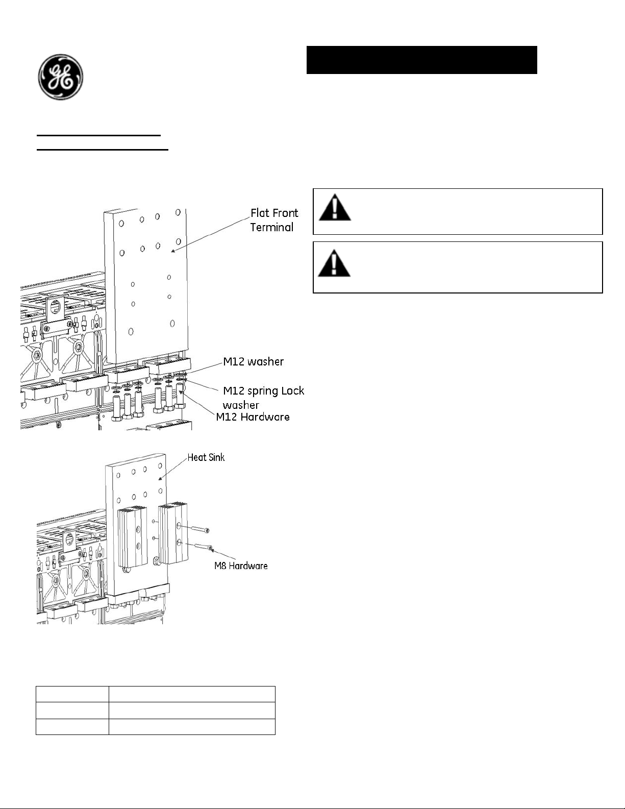
Fig A. Flat front Termination
Fig B. Heat Sink Assembly
Catalogue No:
Catalog # Description
GBB3TBF3 Envelope 3-3pole 4000-6000A
GBB3TBF4 Envelope 3-4pole 4000-6000A
DEH-41463 Installation Instructions
EntelliGuard ® G Circuit Breaker
Accessories
Flat Front Terminations for Fixed
Breaker
Flat Front Terminations Assembly Procedure:
1. Turn the breaker off and discharge the closing
springs by depressing the OFF and ON buttons in
the sequence OFF-ON-OFF. Verify that the
breaker OFF-ON indicator shows OFF on a green
background and that the charge indicator shows
DISCHARGE on a white background.
2. Assemble the Flat Front to the rear terminals with
M12 Hardware as shown in Fig A., Tighten the
hardware to torque 50N-m (36.9 ft-lbs)
3. Assemble the Heat Sink with M8 Hardware to Flat
Front as shown in Fig B. Tighten to torque 1214N-m (8.9-10.3 ft-lbs)
4. Similarly populate the Flat Front and Heat sink on
all other terminals as shown in fig B & C.
5. The bus bars to be supported within 200mm
distance and tightened to 50Nm (36.9 ft-lbs)
torque.
WARNING: Before installing any accessories, turn the
breaker OFF, disconnect it from all voltage sources,
and discharge the closing spings.
AVERTISSEMENT: Avant d’installer tout accessoire,
mettre le disjoncteur en position OFF, le déconnecter
de toute tension d’alimentation, et décharger les
resorts d’armement
1
Page 2
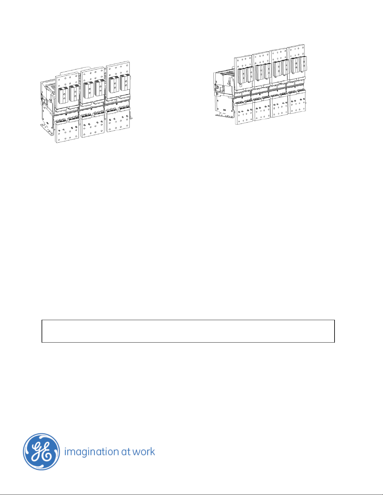
Fig C. Envelope 3, 3 Pole
These instructions do not purport to cover all details or variations in equipment nor, to provide contingency to be met in connection
with installation, operation, or maintenance. Should further information be desired, or should particular problems arise which are not
covered sufficiently for the purchaser’s purposes, the matter should be referred to GE.
GE
41 Woodford Ave, Plainville, CT 06062
www.geelectrical.com
© 2009 General Electric Company
Fig D. Envelope 3, 4 Pole
DEH-41463 R01 (06/09)
2
 Loading...