

Page 1
Introduction
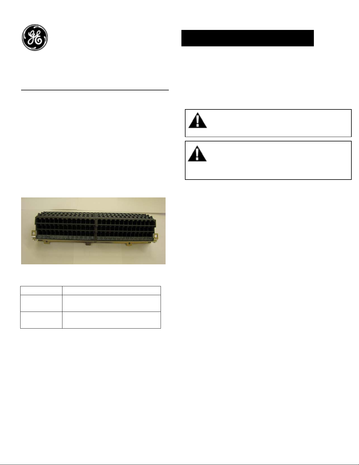
Fixed Secondary Disconnect (Breaker Mounted):
Fixed breakers are always supplied with a
secondary disconnect (auxiliary connection block)
suitable for 39 connection points (terminal A). When
the number of factory installed accessories exceeds
the available number of connection points needed,
nd
a 2
connection block is automatically added
(terminal B). For cases where the accessories are
mounted in the field, an additional auxiliary
connection block can be added to provide 39 more
additional connections.
Figure 1. SD Two-Block Kit
Catalog No Description
Aux, Disconnect Top Fixed 39
GSDFTR1
GSDFTR2
terminal
Aux, Disconnect Top Fixed 78
terminal
DEH-41417 Installation Instructions
EntelliGuard ® G Circuit Breaker
Accessories
Fixed Secondary Disconnect
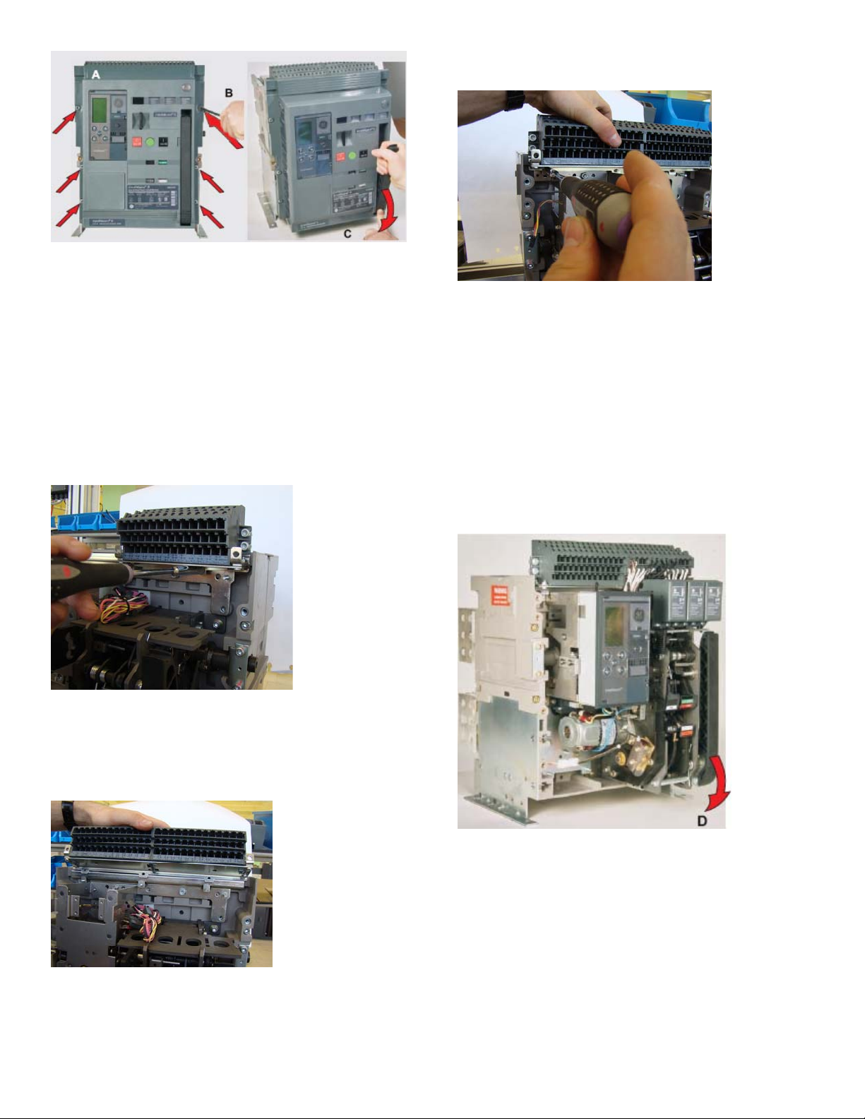
Use the following procedure to install Fixed
Secondary Disconnect accessory into the circuit
breaker.
1. Turn the breaker off and discharge the closing
springs by depressing the OFF and ON buttons in
the sequence OFF-ON-OFF. Verify that the
breaker OFF-ON indicator shows OFF on a green
background and that the charge indicator shows
DISCHARGE on a white background. If installing
in a draw-out type breaker remove breaker from
adaptor (cassette) before continuing.
2. Loosen the 6 screws on front cover (fascia)
using a posidrive screw driver as shown in Fig 1.B
Rotate the charging handle down and slide the
front cover over the handle to remove the front
cover as shown in Fig. 1.C.
WARNING: Before installing any accessories,
turn the breaker OFF, disconnect it from all
voltage sources, and discharge the closing
AVERTISSEMENT: Avant d’installer tout
accessoire, mettre le disjoncteur en position
OFF, le déconnecter de toute tension
d’alimentation , et décharger les resorts
1
Page 2
7. Assemble back the 3 nuts as shown in fig 4.
Figure 1. (A) Front Cover (B) Screw Removal (C) Handle
Rotation
3. Remove all the coils (refer to DEH41411.)
4. Remove all the equipment wiring and accessories
wiring from the secondary disconnect.
5. Remove the 3 nuts as shown in fig 2.
Figure 4. Nuts assembly
8. Complete the SD Wiring.
9. Assemble back all the coil accessories (refer to
DEH41411).
10. To reinstall the cover, rotate the charging
handle down and slide the front cover over the
handle to assemble the front cover to housing as
shown in Fig. 5
Figure 2. Nut Removal
6. Replace the one block assembly with the 2-block
assembly as shown in fig 3.
Figure 3. SD assembly
Figure 5.
11. Ensure the fascia is aligned properly with the
trip unit and the pad lock features of the breaker.
12. Fasten the 6 mounting screws of fascia with
the housing using a pozidrive screwdriver. Apply
torque of 6 Nm (4.42 ft-lbs).
2
Page 3

Secondary Disconnect Wiring Table:
Block A layout
A1 A2 A3 A4 A5 A6 A7 A8 A9 A10 A11 A12 A13
MOTOR MOTOR SPR/ RTC SPR/ RTC ST1 ST1 UV1 UV1 CC COM CC IMM CC CMD ST2/UV2 ST2/UV2
A14 A15 A16 A17 A18 A19 A20 A21 A22 A23 A24 A25 A26
NC3 NC3 NC2 NC2 NC1 NC1 NO3 NO3 NO2 NO2 NO1 NO1
A27 A28 A29 A30 A31 A32 A33 A34 A35 A36 A37 A38 A39
O/P1a O/P1b O/P2 a O/P2b 24V+ 24V- BA NC BA NO BA COM N RC- N RC+ Eleg- CT Eleg- CT
Block B layout
B1 B2 B3 B4 B5 B6 B7 B8 B9 B10 B11 B12 B13
INPUT1 INPUT2 I/P com
ST1 NO /
NC8
ST1 NO /
NC8
UV1 NO /
NC7
UV1 NO /
NC7
NC6 NC6 NC5 NC5 NC4 NC4
B14 B15 B16 B17 B18 B19 B20 B21 B22 B23 B24 B25 B26
CC NO/
NO8
CC NO/
NO8
ST2/UV2
NO7
NO /
ST2/UV2
NO7
NO /
NO6 NO6 NO5 NO5 NO4 NO4
B27 B28 B29 B30 B31 B32 B33 B34 B35 B36 B37 B38 B39
ZSI OUT+ ZSI OUT+ ZSI IN+ ZSI IN- Iso GND 5V Iso Tx_EN_1 RX TX GND Volt-A Volt-B Volt-C
These instructions do not purport to cover all details or variations in equipment nor, to provide contingency to be met in connection
with installation, operation, or maintenance. Should further information be desired, or should particular problems arise which are not
covered sufficiently for the purchaser’s purposes, the matter should be referred to GE.
GE
41 W
oodford Ave, Plainville, CT 06062
www.geelect
© 2009 General Elec
rical.com
tric Company
-
3
 Loading...