

Page 1
Introduction
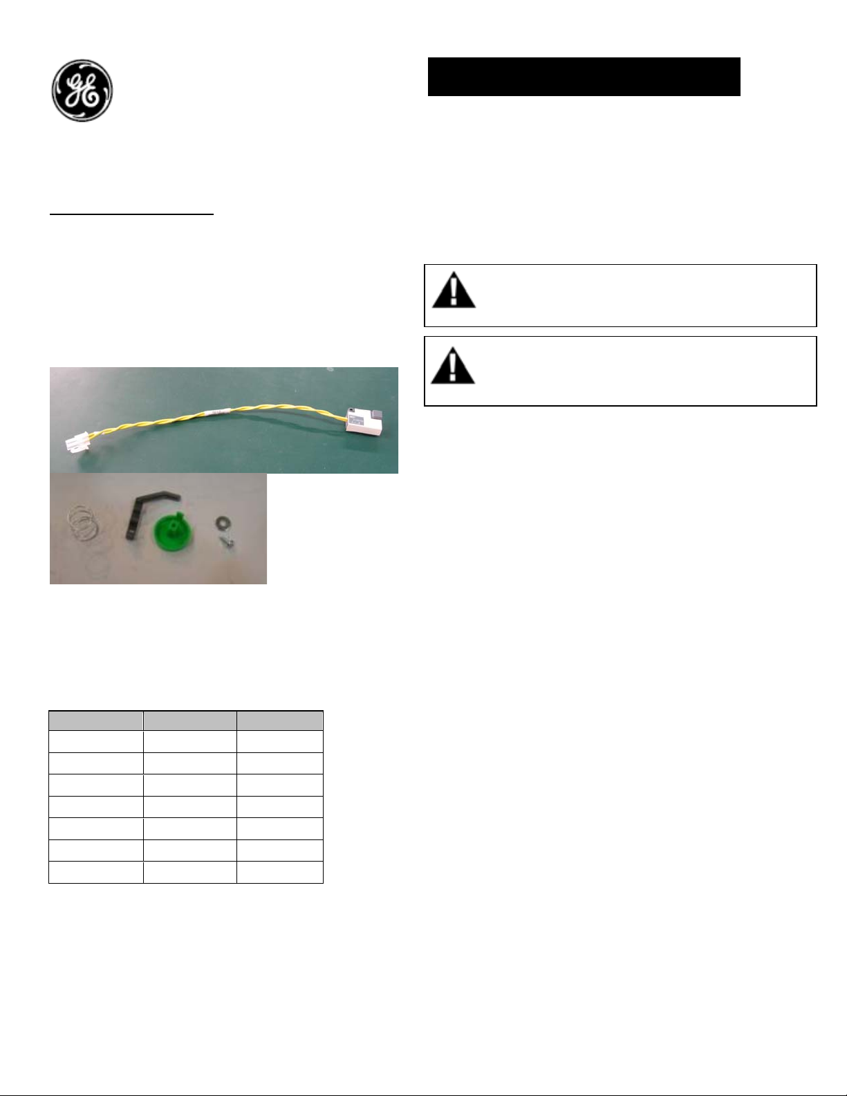
Electrical close switch:
Electrical close switch is an optional accessory
which can be used in combination with the
command Close coil. It has an extra ‘ON’ push
button that fits onto the breaker front fascia,
which can be locally operated manually to close
the breaker.
Figure 1.
Catalog Number: GECPR
Table 1. Electrical close switch push button can be
used with the below Command close coils
Catalog No DC Voltage AC Voltage
GCCC024DR 24V
GCCC030DR 30V
GCCC048R 48V 48V
GCCC060DR 60-72V
GCCC120R 110-130V 110-130V
GCCC208AR 208V
GCCC240R 220-240V 220-240V
DEH-41374 Installation Instructions
EntelliGuard ® G Circuit Breaker
Accessories
Electrical close switch
WARNING: Before installing any accessories, turn the
breaker OFF, disconnect it from all voltage sources,
and discharge the closing spings.
AVERTISSEMENT: Avant d’installer tout accessoire,
mettre le disjoncteur en position OFF, le déconnecter
de toute tension d’alimentation , et décharger les
resorts d’armement
Use the following procedure to install the
Command Closing Coil accessory into the circuit
breaker.
1. Turn the breaker off and discharge the closing
springs by depressing the OFF and ON buttons in
the sequence OFF-ON-OFF. Verify that the
breaker OFF-ON indicator shows OFF on a green
background and that the charge indicator shows
DISCHARGE on a white background. If installing
in a draw-out type breaker remove breaker from
adaptor (cassette) before continuing.
2. Loosen the 6 screws on front cover (fascia)
using a posidrive screw driver as shown in Fig 1.B
Rotate the charging handle down and slide the
front cover over the handle to remove the front
cover as shown in Fig. 1.C.
1
Page 2
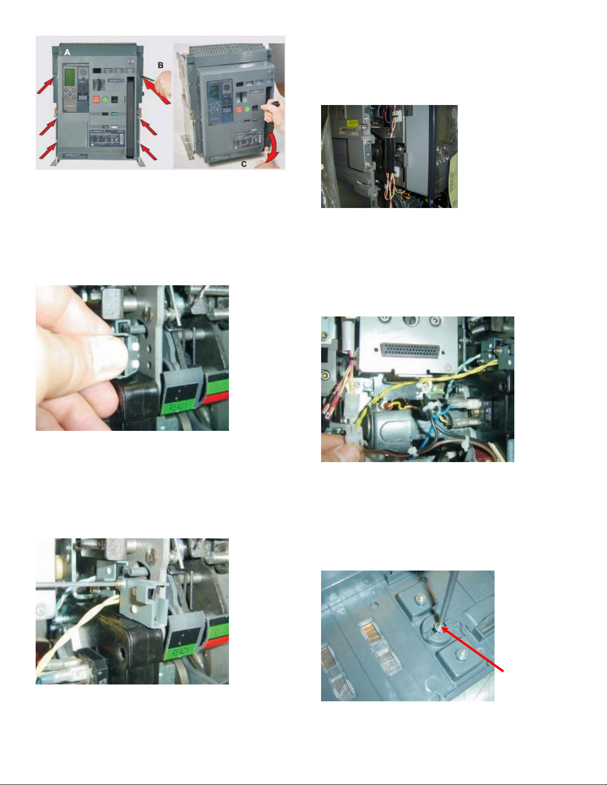
5. Route the wire from the close coil to the side of
the PMU base and pass thru the insulation tube
for the connection with Electrical close switch as
shown in fig.5
Figure 2. (A) Front Cover (B) ScrewRemoval (C) Handle
Rotation
3. Slide the switch assembly over the mechanism
side sheet and locate in the two locating holes as
shown in Fig. 3
Figure3. EC switch assembly
4. Assemble the screw with washer as shown in
Fig. 4. Tighten the screw to torque 1.2N-m (0.9 ftlbs).
Figure5.
6. Plug the connector from the EC switch
assembly to the connector from the command
closing coil beside the PMU base as shown in
Fig 6. Connect the other end of the harness to the
command close coil
Figure 6. Connector plug assembly
Installation of Push button on the fascia:
7. Remove the existing dummy button by
removing the screw as shown in fig 7.
Figure 4. Screw assembly
Figure 7
Dummy button
Screw
2
Page 3

8. Insert the push button and the spring from the
front of the fascia. Assemble them to the fascia
with the screw & washer as shown in fig 8.
Fig 8. Push button assembly
9. To reinstall the cover, rotate the charging
handle down and slide the front cover over the
handle to assemble the front cover to housing as
shown in Fig. 9.
Figure 9.
10. Ensure the fascia is aligned properly with the
trip unit and the pad lock features of the breaker.
11. Fasten the 6 mounting screws of fascia with
the housing using a pozidrive screwdriver. Apply
torque of 6 Nm (4.42ft-lbs).
3
Page 4

Reference:
Command Closing Coil Connection Scheme:
These instructions do not purport to cover all details or variations in equipment nor, to provide contingency to be met in connection
with installation, operation, or maintenance. Should further information be desired, or should particular problems arise which are not
covered sufficiently for the purchaser’s purposes, the matter should be referred to GE.
GE
41 Woodford Ave, Plainville, CT 06062
www.geelectrical.com
© 2009 General Electric Company
-
4
 Loading...