

Page 1
Introduction
Drawout Secondary Disconnect:
Drawout breakers are always supplied with one
secondary disconnect (auxiliary connection block)
suitable for 39 connection points (terminal A).
When the number of factory installed accessories
exceeds the available number of connection
nd
points needed, a 2
automatically added (terminal B) to the Breaker.
For cases where the accessories are mounted in
the field, or needed for the cassette an additional
auxiliary connection block can be added to
provide 39 more additional connections.
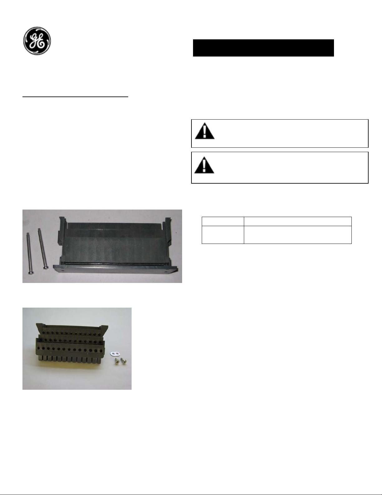
Figure 1. SD Breaker End
Figure 2. SD Cassette End
connection block is
DEH-41401 Installation Instructions
EntelliGuard ® G Circuit Breaker
Accessories
Drawout Secondary Disconnect
WARNING: Before installing any accessories, turn the
breaker OFF, disconnect it from all voltage sources,
and discharge the closing spings.
AVERTISSEMENT: Avant d’installer tout accessoire,
mettre le disjoncteur en position OFF, le déconnecter
de toute tension d’alimentation , et décharger les
resorts d’armement
Catalog Number:
Catalog No Description
GSDWTR Aux, Disconnect Drawout 39
terminal
Use the following procedure to install the
Drawout Secondary Disconnect accessory into
the circuit breaker.
Installation of Breaker side Secondary disconnect:
1. Turn the breaker off and discharge the closing
springs by depressing the OFF and ON buttons in
the sequence OFF-ON-OFF. Verify that the
breaker OFF-ON indicator shows OFF on a green
background and that the charge indicator shows
DISCHARGE on a white background. If installing
in a draw-out type breaker remove breaker from
adaptor (cassette) before continuing.
2. The breaker should be safely isolated and fully
removed from the cassette.
3. Place the secondary disconnect block on the
mounting bracket and assemble the two
mounting screws as shown in fig 3 & 4
.
1
Page 2
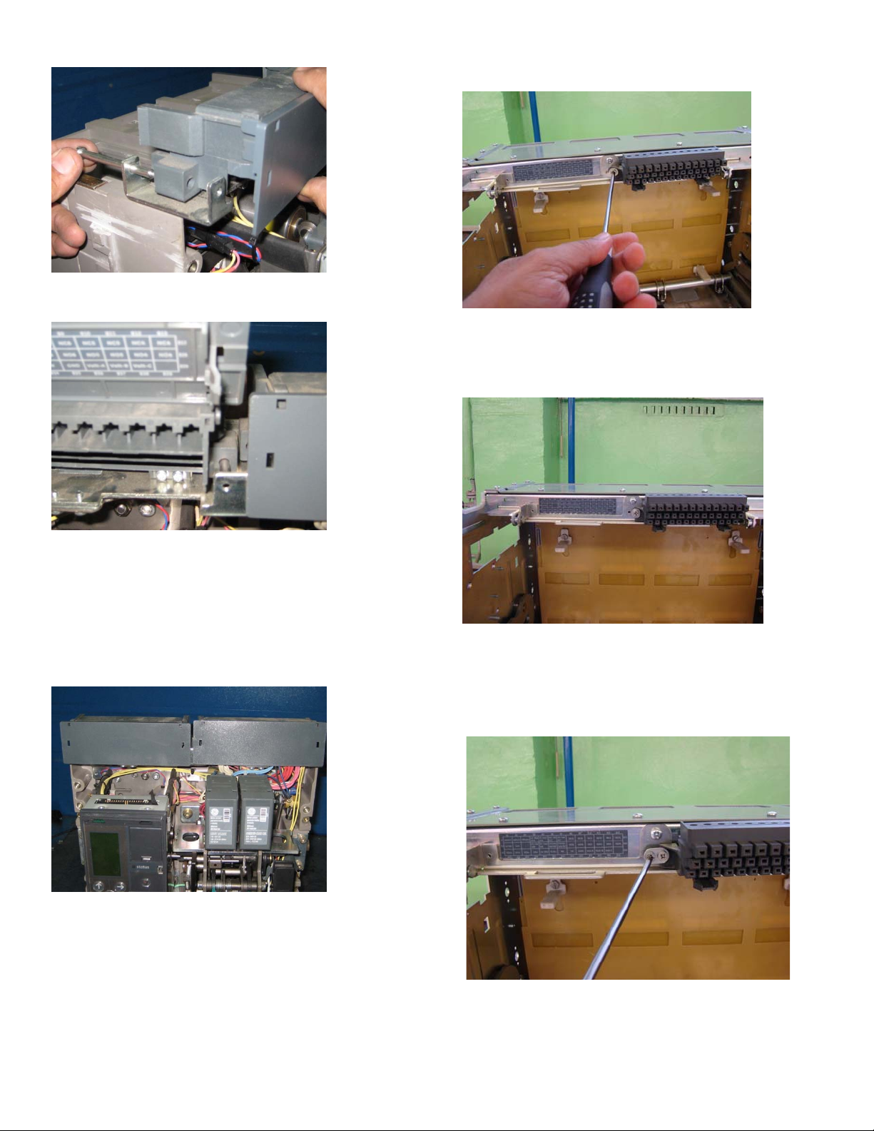
1. Remove the screw shown in the fig 6.
Figure 3. Screws assembly
Figure 4. Screws assembly
4. Push the secondary disconnect block toward
the back of the mounting plate of the breaker and
ensure it is inline with the first block as shown in
fig 5.
Figure 6. Removing the screw
2. Assemble the label as shown in the fig 7.
Figure 7. Label assembly
3. Assemble the new SD block as shown in fig 8 &
9.
Figure 5. SD assembly
Installation of Cassette side Secondary disconnect:
Figure 8.
2
Page 3

2. Any "ADVANCED FEATURES" are selected in
breaker/trip unit Catalog Digit 19
3. A COIL SIGNALING CONTACT OPTION is
selected, Digit 12
4. A READY TO CLOSE signal via the trip unit is
selected, Digit 13
5. Any of the following OPTIONAL Aux. Contact
Switches are selected in Digit 12
- 8NO/NC POWER RATED
Figure 9. Assembly of SD block
4. Complete the wiring of the new accessories to
the secondary disconnect block (refer wiring
diagram on the next page). Assemble back the
breaker in the cassette.
Note:
Secondary Disconnect Block B is Required When:
1. Any "ZONE SELECTIVE INTERLOCKING"
options are selected in breaker/trip unit Catalog
- 3NO/NC POWER RATED + 2NO/NC HIFI
- 4NO/NC POWER RATED + 4NO/NC HIFI
NOTE: Side Secondary Disconnects are
specifically intended for 5-High ("high density")
equipment designs
With Side Mounted Disconnects (SSD), The
following Aux Switches are not valid (In Digit 12);
Auxiliary Switch, 8NO+8NC (Power Rated) or Aux.
Switch, 4NO/4NC (Power Rated) + 4NO/4NC (High
Fidelity)
Digit 18
Reference:
Secondary Disconnect Wiring Table:
Block A layout
A1 A2 A3 A4 A5 A6 A7 A8 A9 A10 A11 A12 A13
MOTOR MOTOR SPR/ RTC SPR/ RTC ST1 ST1 UV1 UV1 CC COM CC IMM CC CMD ST2/UV2 ST2/UV2
A14 A15 A16 A17 A18 A19 A20 A21 A22 A23 A24 A25 A26
NC3 NC3 NC2 NC2 NC1 NC1 NO3 NO3 NO2 NO2 NO1 NO1
A27 A28 A29 A30 A31 A32 A33 A34 A35 A36 A37 A38 A39
O/P1a O/P1b O/P2 a O/P2b 24V+ 24V- BA NC BA NO BA COM N RC- N RC+ Eleg- CT Eleg- CT
Block B layout
B1 B2 B3 B4 B5 B6 B7 B8 B9 B10 B11 B12 B13
INPUT1 INPUT2 I/P com
B14 B15 B16 B17 B18 B19 B20 B21 B22 B23 B24 B25 B26
B27 B28 B29 B30 B31 B32 B33 B34 B35 B36 B37 B38 B39
ZSI OUT+ ZSI OUT+ ZSI IN+ ZSI IN- Iso GND 5V Iso Tx_EN_1 RX TX GND Volt-A Volt-B Volt-C
ST1 NO /
NC8
CC NO/
NO8
ST1 NO /
NC8
CC NO/
NO8
UV1 NO /
NC7
ST2/UV2
NO7
NO /
UV1 NO /
NC7
ST2/UV2
NO7
NO /
3
NC6 NC6 NC5 NC5 NC4 NC4
NO6 NO6 NO5 NO5 NO4 NO4
Page 4

These instructions do not purport to cover all details or variations in equipment nor, to provide contingency to be met in connection
with installation, operation, or maintenance. Should further information be desired, or should particular problems arise which are not
covered sufficiently for the purchaser’s purposes, the matter should be referred to GE.
GE
41 Woodford Ave, Plainville, CT 06062
www.geelectrical.com
© 2009 General Electric Company
-
4
 Loading...