

GE Industrial Solutions EntelliGuard G DRAWOUT CASSETTE KEY LOCKING User Manual [en, de, pl]
Page 1

SSO
S
EntelliGuard-G
ACCE
DEH-41380
RIE
Instruction sheet
Gebrauchsanleitung
Instrukcja arkuza
-DRAWOUT CASSETTE KEY LOCKING
-EINSCHUBTECHNIK SCHUSSELSPERRE
-Zamek w podstawie wył¹cznika wysuwnego
DEH-41380 R02 R0914704 10/09
Page 2
EntelliGuard G
Instruction sheet
4.4
ACCESSORIES
Gebrauchsanleitung Instrukcja
4.4.4 Drawout Cassette Key Locking
Two locks can be mounted. The locking device has
the following functionality:
1. Locks the entry aperture of the racking handle in
closed position.
2. Locks the breaker moving portion in the cassette
in one the following positions:
DISCONNECTED , TEST OR CONNECTED.
3. Locks the breaker in 'OFF' position and prevents
it from being switched ON.
Two locks can be placed .
- RONIS 1104B Standard key 1/4 inch clockwise
rotation to trap the key.
-OR-
- PROFALUX B204DY With key type S1 1/4 inch
clockwise rotation to trap the key.
The device is available in two versions.
1. Factory mounted mechanism:
The breaker/device is supplied off works with all
cam's and screws allowing the user to mount a
separately acquired GE type lock kit.
2. Field mountable device:
A kit is supplied allowing the field mounting of the
locking mechanism and allowing the use of a lock
of the correct type purchased elsewhere.
Installation of key locks on Cassette.
1. Remove the knock-out feature on the Cassette
front panel (Fig. A) & clean the flash with any sharp
pointed Tool. Ensure no flash or projections left out
& cavity is free for insertion of lock.
2. Remove M22 nuts from the Ronis /Profalux lock.
3. Insert the Lock body in to the front panel cavity.
4.4.4 Einschubtechnik Schlüsselsperre
Maximal zwei Schlüsselsperren können für die
folgenden Sicherheitsfunktionen eingesetzt werden:
1. Verriegelt das Zugangsloch für die Einfahrkurbel
in geschlossener Stellung.
2. Verriegelt die Schalterbewegung innerhalb des
Einschubträgers in einer der folgenden Stellungen:
GETRENNT, TEST oder BETRIEB.
3. Verriegelt den Schalter in der AUS-Stellung und
verhindert die EIN-Schaltung.
Die zwei Schlüsselsperren-Fabrikate:
- RONIS 1104B mit Standardschlüssel 1/4 Zoll
Uhrzeigersinndrehung zur Schließung
-ODER-
- PROFALUX B204DY mit Schlüsseltyp S1 1/4 Zoll
Uhrzeigersinndrehung zur Schließung.
Diese Teile sind in 2 Versionen verfügbar:
1. Werkseitig montiert
Der Schalter wird mit allen Teilen, Hebeln und
Schrauben, zur vollständigen Sperrmontage
geliefert.
2. Vorort-montierbare Version:
Ein Bausatz erlaubt den Vororteinbau der
Sperrenmechanik mit passenden, fremdgekauften
Schlössern.
Montage der Einschubträger-Schlüsselsperre
1. Entfernen Sie die Ausbrechöffnung an der
Einschubträger-Frontplatte (Abb. A) und entgraten
Sie den Ausbrechrest. Stellen Sie sicher, dass keine
Gratreste die Schlosssperre behindern.
2. Entfernen Sie die M22-Mutter vom Ronis /
Profalux Schlüsseleinsatz.
4.4.4 Zamek w podstawie wyłącznika
wysuwnego
Stosowane sa dwa rodzaje zamków. Ich funkcje sa
nastepujace:
1. Zamkniecie otworu korby gdy wylacznik jest
zamkniety
2. Zablokowanie czesci ruchomej wylacznika w
podstawie w nastepujacych polozeniach:
ODLACZENE, TEST, PRACA
3. Zablokowanie wyłącznika w stanie otwarcia (OFF)
i uniemożliwienie jego zamknięcia (ON).
Mozna stosowac dwa rodzaje zamków.
- RONIS 1104B ze standardowym kluczem 1/4 cala,
obracanym w prawo do zatrzaśnięcia klucza. LUB-
- PROFALUX B204DY z kluczem typu S1, rozmiar
1/4 cala, obracanym w prawo do zatrzaśnięcia
klucza. Zamki są dostępne w dwóch wersjach.
1. Mechanizm montowany fabrycznie:
Wylacznik z mechanizem jest dostarczany z linii
produkcyjnej ze wszystkimi elementami i
zamocowaniami które umozliwiaja uzytkownikowi
zalozenie zamka zakupionego oddzielnie w GE.
2. Zamek montowany samodzielnie:
Zestaw w tej wersji umożliwia samodzielny montaż
mechanizmu blokującego i zastosowanie
odpowiedniego zamka zakupionego u inndego
dostawcy.
Zamocowanie zamków w podstawie
1. Wyłamać okienko w przednim panelu podstawy
wyłącznika (Fot. A) i oczyścić krawędzie. Sprawdzić
czy w otworze nie pozostały krawędzie lub
nierówności utrudniające włożenie zamka.
2. Usunąć nakrętki M22 z zamka Ronis /Profalux.
Catalogue Numbers Factory mounted Field kit or Spare
--------------------------------------------------------------------------------------------------------Kit for 1 RONIS lock (max. 2) GCRON GCRONR
Kit for 1 PROFALUX lock (max. 2) GCPRO GCPROR
--RONIS Lock GRON
LOCKS
PROFALUX Lock GPRO
Assemble M22 nut on to lock body from inside of
cassette & Turn until it reaches Cassette base plate
face. Don't tighten, keep loose.
4. Assemble the key lock cam on to the Lock body.
Orient on the slot. Tighten nut supplied along with
lock body. Ensure that Camming Surface of the cam
is in contact with pivot of key Lock actuator bracket
fitted on Cassette.
5. Fully tighten the M22 nut.
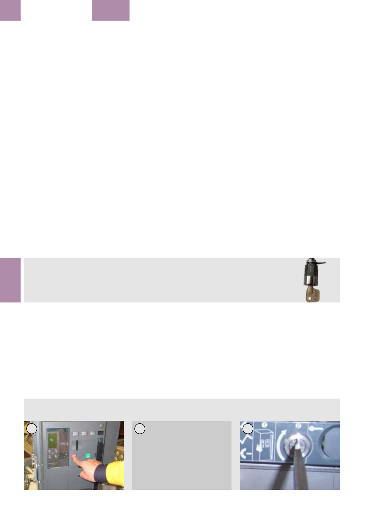
Key lock operation.
1. Ensure position indicator shows
DISCONNECTED/TEST/CONNECTED Position.
2. Remove racking handle from the Crank insertion
aperture if the handle is in place.
Fig. A: Press the off button on the breaker
Fig. B: Key lock key rotate anti clock wise
Fig. C: Device locked out
3. Stecken Sie den Schlüsseleinsatz das
Frontplattenloch. Montieren Sie die M22-Mutter von
innen auf das Schlüsseleinsatzgewinde und ziehen
Sie es leicht an. Nicht festziehen.
4. Setzen Sie den Schlüsselsperre-Mitnehmer auf
den Schlüsseleinsatz. Mitgelieferte Mutter am
Einsatz festziehen. Stellen Sie sicher, dass der
Schlüsselmitnehmer richtig im Eingriff mit den
Funktionsteilen des Einschubträgers ist.
5. Ziehen Sie die M22-Mutter vollständig an.
Schlüsselsperren-Betrieb:
1. Stellen Sie sicher, dass die Stellungsanzeige
vollständig auf GETRENNT/TEST/ oder BETRIEBsStellung steht.
2. Entfernen Sie den Drehgriff aus dem
Kurbeleinführungsloch, falls noch vorhanden.
Abb. A: Drücken der AUS-Taste
Abb. B: Schlüsselsteller drehen
Abb. C: Gerät gesperrt
BA
3. Włożyć korpus zamka w zagłębienie w płycie
czołowej. Założyć nakrętkę M22 na korpusie zamka
od wewnętrznej strony podstawy i obracać aż do
miejsca gdy zetknie się z płytą bazową podstawy.
Nie doręcać, pozostawić luźno.
4. Włożyć krzywkę zamka do korpusu zamka.
Ustawić w gnieździe. Dokręcić nakrętkę
dostarczoną z korpusem zamka. Sprawdzić czy
powierzchnia działania krzywki styka się i
prawidłowo współpracuje z elementami zamka w
podstawie.
5. Dokręcić całkowicie nakrętkę M22.
Obsluga zamków.
1. Sprawdzić czy wskaźnik położenia wskazuje
pozycję ODŁĄCZONY / TEST / PRACA.
2. Wyjąć korbę z napędu wsuwania.
3. Wcisnąć przycisk OFF na płycie czołowej
Fot. A: Wciśnięcie przycisku OFF w wyłączniku
Fot. B: Obróccenie kluczs przeciwnie do ruchu
wskazówek zegara
Fot. C: Odblokowanie
C
4.4-04
Page 3

Instruction sheet
Gebrauchsanleitung Instrukcja
3. Press the OFF button on the breaker facia & open
the breaker. Shown in Fig. A.
4. Turn the key on the key lock anticlockwise by 90
degree till it reaches dead stop (Fig. B). Remove the
key. Device is now locked out.
Verification that security locking is in place.
5. It should not be possible to open the racking
handle aperture shutter. Verify this by attempting to
open the shutter drive by placing a screwdriver and
rotating it clockwise as depicted in Fig. C.
6. It should not be possible to switch the breaker
'ON'. Verify this by attempting to turn the breaker
'ON' by depressing the 'ON' switch button on the
breakers front fascia.
-------------------------------------------------------------
3. Drücken Sie die AUS-Taste auf der
Leistungsschalter-Frontabdeckung und öffnen Sie
damit den Leistungsschalter wie in Abb. A.
4. Drehen Sie den Schlüssel der Schlüsselsperre
gegen den Uhrzeigersinn um 90°, bis zum Ende
(Abb.B). Entfernen Sie den Schlüssel. Das Gerät ist
nun gesperrt.
Nachprüfung, der Sicherheitssperrung-Funktion:
5. Es sollte nicht möglich sein die Blende zu drehen
und die Einfahrkurbel in das Kurbeleinführloch der
Frontblende zu stecken. Prüfen Sie dies bitte durch
Drehen der Stellschraube der Einfahrkurbelblende
mit Schraubendreher im Uhrzeigersinn, wie Abb. C.
6. Versuchen Sie zur Schließung des
Leistungsschalters die EIN-Taste zudrücken. Die
Sperrung sollte das Einschalten des
Leistungsschalters nicht zulassen.
------------------------------------------------------------
ACCESSORIES
wyłącznika i otworzyć wyłącznik (Fot. A).
4. Obrócić klucz w zamku przeciwnie do
wskazówek zegara o 90 stopni, aż do
zatrzymania (Fot. B). Wyjąć klucz. Teraz
urządzenie jest zablokowane.
Sprawdzenie skuteczności blokad.
5. Otworzenie otworu dla korby nie powino być
możliwe. Sprawdzić próbując otworzyć
przesłonę wkrętakiem, obracając zgodnie z
ruchem wskazówek zegara w sposób pokazany
na Fot. C.
6. Zamknięcie wyłącznika (ON) powinno być
niemożliwe. Sprawdzić próbując zamknąć
wyłącznik przez wciśnięcie przycisku 'ON' na
płycie czołowej wyłącznika.
--------------------------------------------------------
EntelliGuard G
4.4
4.4.5 Door Interlock device
(Drawout pattern only)
A field mountable accessory, the door Interlock
device can be mounted to the drawout breakers
cassette. It prevents the user from inadvertently
opening the door when the beaker is in the
CONNECTED position.
Their are two variants one suited for LEFT and
one for RIGHT hinging doors.
Fig. A contains one door interlock kit.
Door Interlock
A door interlock mechanism may be fitted inside
the cassette on the right for L/H hinged door or
left for R/H hinged door.
Assembly
Place spring over the spring pin protruding from
cassette side plate. Position interlock lever as
shown. Ensure one end of spring leg locates
below second pin and the other leg rests on
bottom edge of lever. See Fig. B.
Holding lever in position:
- insert circlips one each into the groove in the
spring pin & Second Pin.
4.4.5 Türverriegelung
(Nur für Ausfahrtechnik)
Als ein vorort-montierbares Zubehör kann die
Türverriegelung an den Einschubträger der
Ausfahrtechnik-Anlage angebaut werden. Es
schützt den Anwender vor unbeabsichtigtem
Öffnen der Anlagentür, solange der
Leistungsschalter noch in der BETRIEBS-Stellung
ist.
Zwei Varianten sind erhältlich, eine für LINKSund eine für RECHTS-angeschlagenen Türen.
Abb. A zeigt einen Türverriegelungsanbausatz.
Tür-Verriegelung
Ein Türverriegelungsmechanik kann innerhalb
des Einschubträgers auf der rechten Seite für L /
Catalogue Number Field kit or Spare
--------------------------------------------------------Door interlock LEFT GLHD
Door interlock RIGHT GRHD
H aufklappbaren Türen oder links für R / H
aufklappbaren Türen befestigt werden.
Zusammenbau
Montieren Sie die Spiralfeder über die
Federaufnahme, die aus der Einschubplatte
hervorsteht. Positionieren Sie den
Verriegelungshebel wie dargestellt. Stellen Sie
sicher, dass sich ein Ende des Federschenkels
unten dem zweiten Butzen und der andere
Schenkel auf dem unteren Rand des Hebels
eingehakt ist. Siehe Abb. B.
Haltehebel in Stellung bringen:
- Legen Sie die Sprengringe ein, einen in die Nut
im Federaufnahmebutzen und in den 2. Butzen.
4.4.5 Blokada drzwi
(Tylko dla wersji wysuwnych)
Blokada jest przeznaczona do samodzielnego
montażu, jest mocowana w podstawie
wyłącznika wysuwnego. Uniemożliwia
użytkownikowi przypadkowe, niezamierzone
otwarcie drzwi, gdy wyłącznik jest w położeniu
PRACA. Blokada jest dostępna w dwóch
wersjach: do założenia z LEWEJ lub PRAWEJ
strony drzwi zamocowanych na zawiasach.
Fot. A przedstawia jeden zestaw blokady drzwi.
Blokada drzwi
Mechanizm blokady drzwi może być
zamocowany wewnątrz podstawy po prawej
stronie w przypadku drzwi na zawiasach z lewej
DOOR
strony (L/H), lub po lewej stronie w przypadku
drzwi na zawiasach z prawej strony (R/H).
Zamocowanie
Zalozyc sprezyne na sworzniu wystajacym z
bocznej plyty podstawy. Ustawic dzwignie
blokady zgodnie z rysunkiem. Sprawdzic czy
jeden z konców sprezyny znajduje sie ponizej
drugiego sworznia a drugi koniec opiera sie na
dolnej krawedzi dzwigni. Patrz: Fot. B.
Utrzymanie dzwigni w polozeniu:
- założyć pierścień sprężynujący na rowkach w
sworzniu sprężyny i na drugim sworzniu.
A
B
4.4-05
 Loading...