

Page 1
Introduction
Door Interlock Kit:
A door interlock mechanism may be fitted inside
the cassette on the right for Left hinged door or
Left for Right hinged door. Specify whether door is
Left Hand or Right hand hinged when ordering.
DEH-41377 Installation Instructions
EntelliGuard ® G Circuit Breaker
Accessories
Door Interlock Kit
WARNING: Before installing any accessories, turn the
breaker OFF, disconnect it from all voltage sources,
and discharge the closing spings.
AVERTISSEMENT: Avant d’installer tout accessoire,
mettre le disjoncteur en position OFF, le déconnecter
de toute tension d’alimentation , et décharger les
resorts d’armement
Use the following procedure to install the Door
Interlock Kit accessory into the circuit breaker.
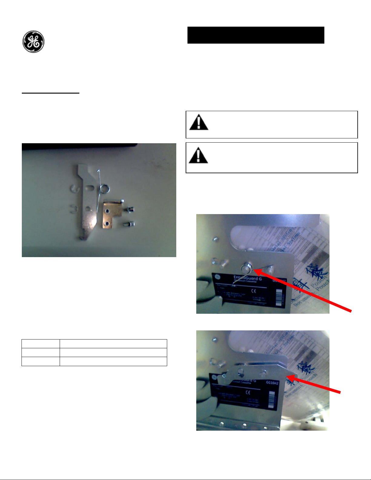
1. Place the spring over spring pin protruding
from cassette side plate as shown in fig 2.
Figure 1
Interlock Packs
Each pack contains an interlock lever, a helical
spring, circlips (Fig. 1). A door bracket & its
mounting screws, washers are also included
Catalog No.
Catalog No Description
GLHD Left Hand door interlock
GRHD Right Hand door interlock
Figure 2
Figure 3
1
Page 2
2. Position interlock lever as shown in Fig 3.
3. Position one leg of the spring below the second
pin and position the other leg of the spring over
the interlock bracket.
4. Holding lever in position; insert circlips one
each into the groove in the spring pin & Second
Pin (Fig. 3). Now the interlock swings in the slot
with respect to the pivot pin 1
5. Based on the door interlock type, drill the hole
pattern on the door as shown in fig 3 & 4.
Dimensions shown are in mm (inches)
Dia 5.3 (0.209)
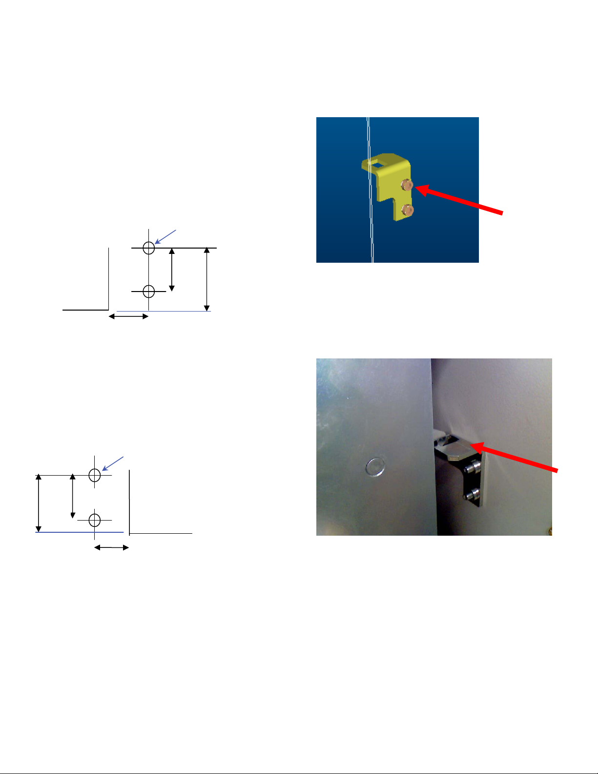
6. Assemble the door bracket to the door using
the screws and washers as shown in fig 5.
L.H hinged
Door cut-out
198
(7.8)
F1, 3P – 32.5 (1.28)
F1, 4P – 132.5 (5.22)
F2, 3P – 67.5 (2.66)
F2, 4P – 197.5 (7.78)
F3, 3P – 222.5 (8.76)
F3, 4P – 340.5 (13.4)
Fig. 3 (GLHD)
Dia 5.3 (0.209)
RH hinged
20 (0.79)
Door cut-out
F1, 3P & 4P – 33.5 (1.32)
F2, 3P & 4P – 98.5 (3.88)
F3, 3P - 240.5 (9.47)
F3, 4P - 355.5 (14.0)
20
(0.79)
198 (7.8)
Figure 5
7. When the door is closed, the bracket on the
door will be hooked to the door interlock on the
cassette as shown in fig 6.
Figure 6
Fig. 4(GRHD)
2
Page 3

These instructions do not purport to cover all details or variations in equipment nor, to provide contingency to be met in connection
with installation, operation, or maintenance. Should further information be desired, or should particular problems arise which are not
covered sufficiently for the purchaser’s purposes, the matter should be referred to GE.
GE
41 Woodford Ave, Plainville, CT 06062
www.geelectrical.com
© 2009 General Electric Company
-
3
 Loading...