

Page 1
A
DEH-4568
®
EntelliGuard
Digital Test Kit
User’s Guide
imagination at work
Page 2
DEH-4568A
WARNINGS, CAUTIONS, AND NOTES AS
USED IN THIS PUBLICATION
WARNINGS
Warning notices are used in this publicati on to emphasiz e that
hazardous voltage, currents, or other conditions that cou l d
cause personal injury are present in this equipment or may be
associated with its use.
Warning notices are also used for situations in which inattention
or lack of equipment knowledge could cause either pe rs on al
injury or damage to equipment.
CAUTIONS
Caution notices are used for situation s in which equipme nt
might be damaged if care is not taken.
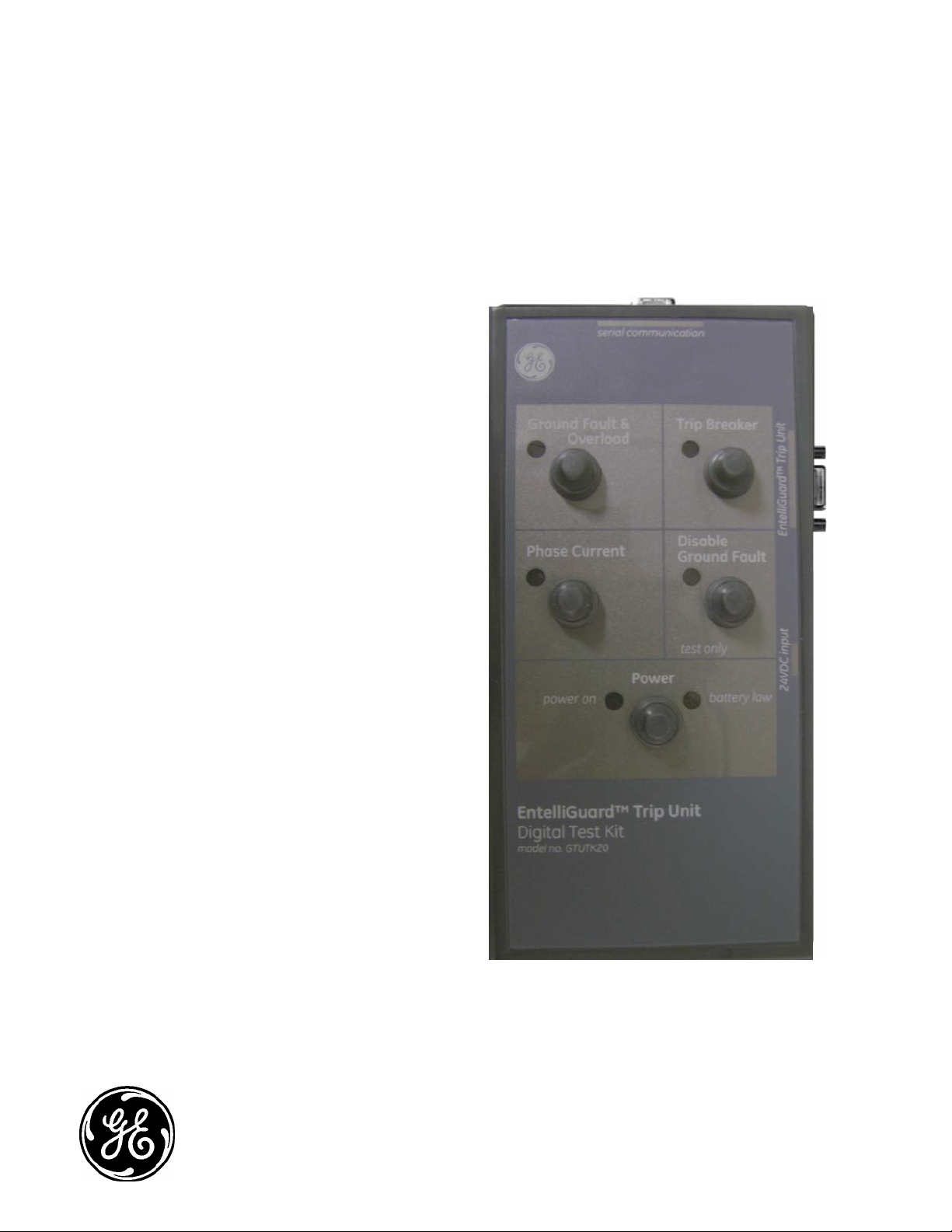
1-1 Description
®
EntelliGuard
TU Test Kit is a lightweight, portable test
instrument designed for field-testing of EntelliGuard TU Trip
Units. The Test Kit includes the following features:
• Operation from a 100-240VAC 50/60 Hz Universal plug supply
or two 9-volt alkaline batteries (batterie s not supplied).
• Provides power to the trip unit for viewing and setting set-
points with less than 15% load on the breaker or if the
replaceable Trip Unit Battery needs replacing.
• Verification of metering (phase simulation)
• Ground Fault Testing with Ground Fault Trip Indication
• Trip test
• Temporarily disable the Ground Fault feature during single
phase breaker testing
1-2 Summary of Operation
The functions of the various switches and LEDs are as follows:
Power Switch
Pressing this button will pow er-up the tri p unit. Th e green
Power LED will indicate that power has been provided to the
trip unit. A red Battery Low LED indicates t hat the batt erie s
in the test kit should be replaced.
NOTES
Notes call attention to information that is especially significant to understanding and operating the equipment.
This document is based on informatio n availabl e at the
time of publication. While efforts have been made to
ensure accuracy, the information co ntaine d herein d oes
not cover all details or variations in hard ware and
software, nor does it provide for every possi ble
contingency in connection with installation, operation, and
maintenance. Features may be described herein that are
not present in all hardware and software systems. GE
Consumer & Industrial assumes no oblig ation of notic e to
holders of this document with respect t o chang es
subsequently made.
GE Consumer & Industrial makes no representation or
warranty, expressed, im plied, or statut ory, with resp ect to,
and assumes no responsibili ty for th e accurac y,
completeness, sufficiency, or usefulness of the
information contain ed here in. No warr ante es of
merchantability or fitness for purpose shall apply.
EntelliGuard is a regist ered tra demark of t he Gener al
Electric Company.
Trip Breaker Switch
Pressing this button will cause the breaker to trip. The switch
has an associated red LED that indicates the state of the
switch. If the LED is illuminated, then switch is ON and firing the
flux shifter to trip the breaker.
Disable Ground Fault
Pressing this button will cause the trip unit GF protection to be
temporarily disabled. To enable the GF, the switch and
associated red LED must be turned off. The GF switch has
an associated red LED that indicates the state of the swit ch
(GF disabled when red LED illuminated).
WARNING: When using EntelliGuard Digital Test Kit to
defeat Ground Fault function of EntelliGuard Trip Units, the
ground fault protection of the trip unit will not be active.
Power to the breaker shou l d b e r e m o v e d p r i o r t o u s i n g t h i s
feature. Before applying load to the breaker, ensure that the
Disable GF LED is OFF or the Test Kit is disconnected from
the trip unit.
Failure to follow this procedure can result in deactivation of
the Trip Unit GF protection.
DEH-4568A Rev. 02 (08/09)
Page 3
1.2 Summary of Operations, Continued
Ground Fault & Overload
Pressing this button will cause a trip either on the
Ground Fault or Overload protection. The switch has a red
LED that is ON when the switch is pressed. This feature will
store the trip event in the Event log and operate the bell
alarm, if available.
CAUTION: With the Phase Current enabled, the
EntelliGuard trip unit will not provide correct protection to
the system, which may result in a trip below desired levels.
Pow e r s h ou l d b e disconnected from the circuit breaker
prio r t o enter i ng Phase Current Mode.
Ensure that the Phase Current LED is OFF when in normal
operation. Failure to follow this procedure can result in
improper operation of the system.
Phase Current
By pressing this switch, the EntelliGuard trip unit
will display approximately 100A on each current phase. This
can be viewed on the trip unit LCD under METER menu. The
switch has a red LED that indicates the state of the switch
(LED On when Switch is ON).
See Figure 1.0
1.3 Specifications
The EntelliGuard Digital Test Kit Catalog Number is
GTUTK20. It includes the following components:
• Test kit box
• 24VDC power supply – CUI Inc., Part Number EMS
240075- P5P-SZ or equivalent.
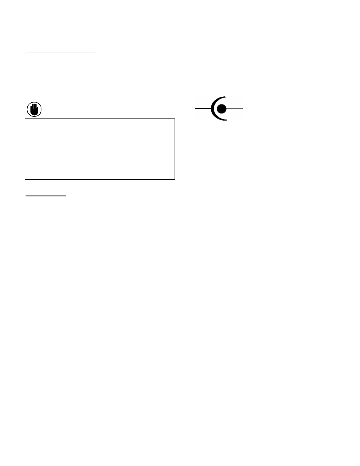
• Voltage polarity is as follows:
- +
• Serial Communication Test Kit cable (6 ft DB9 (male)/DB9
(female) cable). This cable connects the Test Kit to a PC to be
used to download Waveforms and set-up the trip unit via set-up
so f tware . Par t number 45-0314 from GC Electronics or
equivalent. Below is the connection diagram between the
test kit and PC.
Test Kit DB-9 PC Comm port DB-9
2 ---------------------------- 2
3 ---------------------------- 3
5 ---------------------------- 5
• EntelliGuard Trip Unit cable (6-ft. SVGA/VGA Monitor
Extension Cable HD15M to HD15F). This cable connects the
Test Kit to the EntelliGuard Trip Unit. Part Number
SPC20050 from SPC Technology or equivalent. Below is the
connection diagram between the Test Kit and Trip Unit
Test Kit HD15F Trip Unit HD15M
1 ---------------------------- 1
2 ---------------------------- 2
3 ---------------------------- 3
6 ---------------------------- 6
7 ---------------------------- 7
8 ---------------------------- 8
9 ---------------------------- 9
10---------------------------- 10
11---------------------------- 11
Page 4

Figure 1.0 EntelliGuard Test Kit: GTUTK20
9 Pin Connector
Ground Fault
Disable
Phase Current
Power
Trip Breaker
15 Pin Connector
Power Supply
DEH-4568A Rev. 02 (08/09)
Page 5

1.4 Detailed Operation
Cables:
cable that connects to the si de (Ent elliGua rd trip unit
port) of the test kit and to the front of the t rip unit. Thi s
cable al lo w s t h e test kit to power the trip unit and to
apply signals for the test functions provided below.
Note: In some cases removal of the screws from the
15 pin connector on the trip unit side are required.
In addition, the test kit is provided with a 9-pin cable that
connects to the top (serial communication port ) of the test
kit to support Modbus communication. Modbus
communication requires a computer, Mod bus software
and configuration to be used . See the E ntelliGuard Trip
Unit Manual (DEH-4567) for Modbus register information.
Cont ac t yo ur G E A cc o un t Manager for availability of
softwar e sp e cif i c al l y f or u se w i t h the EntelliGuard TU.
Powering the trip unit:
power the trip unit as follows:
• Connect the EntelliGuard Trip Unit cable to the trip unit.
• Press the Power button to power-on the trip unit.
The power ON LED will be lit. The trip unit can also be
power ed by ex ternal 24 V that is wired to th e second ary
disconnect of the c i r c u i t bre a ke r and is powered when
suf fi c ie nt c ur re n t i s flowing through the circuit breaker.
The test kit can be used to pow er the tr ip uni t i n c ases
wh e re c u rr e n t is f l o wi n g th r o u gh the circuit breaker but the
current is insufficient to power the trip unit. App lyi ng
power to the trip unit from the test kit while the trip unit is
powered from another source will not damage the trip
unit. When Power is supplied to the trip unit, the
bright backlight LCD screen will be lit.
Trip Breaker Test:
signals the trip unit to trip the breaker by firing the flux
shifter. This can be used to verify that the flux shifter is
connect ed and installed properly and that the flux shifter
trips the breaker mec hanis m. Th is t est i s per form ed by
havi ng th e t es t k i t connected and the breaker closed and
then pushing the Trip Br eak er but to n. T he bre ak er wil l
then open. No events will be stored in the event log
and no bell alarm will operate.
If trip unit fails to trip the breaker in this test, remove the
breaker from service and refer the trip unit and brea ker to
an authorize d GE service representative.
Ground Fault & Overload Operation:
the Ground Fault test, Short Time and Instantaneous
pickup must be set to 5X or greater. Record all
settings prior to making changes. To perform an
overload test the Ground Fault needs to be disabled
through the test kit. See the following page for
detailed instructions on test set-up.
The Test Kit is provided with a 15-pin trip unit
The test kit can be used to
Pressing the Trip Breaker button
In order to perform
Ground Fault Disable: This feature should only be
used when testing the breaker with the break er
disconnected f r o m t h e so u r c e ( u p st r e a m b r e ak e r o r
switch open or breaker rac ked out ). T his t est is u sed when
perf or min g pr im ary i nj ect io n testing of overcurrent or short
circuit protection features on 1 phase of the circuit
breaker. This single-phase current will appear as a
ground fault to the trip unit due to the phase unbalance
(only 1 phase current applied). The ground fault di s ab l e
feature will allow this testing to occur without the unit
tripping on ground fault. Pressing the Disable Ground Fault
button signals the trip unit to temporarily disable the GF
protection.
WARNING: When using the EntelliGuard Digital
Test Kit to defeat the Ground Fault function of
EntelliGuard Trip Units the ground fault protection of
the trip unit will not be active. Power to the breaker
should be removed prior to using this feature. Before
applying load to the breaker, ensure that the Disable
GF L E D i s O F F o r t h e Test Kit is disconnected from
the trip unit.
Failure to follow this procedure can result in
deactivation of the Trip Unit GF protection.
Phase Current: This feature should only be used when
testing the breaker with the breake r disconnected from
the source (upstream breaker or switch open or
breaker racked out). The phase current button is
used to apply a fixed voltage to the sensing circuitry
for each phase. This will test the measurement ci rc uit ry o f
the t r i p u n i t . I f th e u n i t i s w o r k i n g properly then 100A ±
10A will appear for each phase on the trip unit
METER display. If your trip unit reads lower than 90A
or greater than 110A, please contact your local GE
Field Sales Office.
CAUTION: With the Phase Current enabled, the
Ente lliGuard trip unit will not provide correct
protection to the system, which may result in a trip
below desired levels. Power sh ould be off from the
circuit breaker prior to entering Phase Current mode.
Ensure that the Phase Current LED is OFF when in
normal operation. Failure to follow this procedure
can result in improper operation of the system.
DEH-4568A Rev. 02 (08/09)
Page 6

1.4 Detailed Instructions, Continued
RECORD ALL TRIP UNIT
SETTINGS PRIOR TO TESTING
EntelliGuard TU trip unit test procedure
Initial trip unit set-up
Set Long Time Pick-Up to 50% (allows test signal to cause O/L trip without extremely long time delay)
Set Long Time Delay to any of the lower bands
Set Short Time Pick-Up to 9X (set above expected test current)
Set Short Time Delay to any of the intermediate bands or set to OFF
Set Instantaneous Pick-Up > 5X (to prevent instantaneous trip with test kit input)
Set Ground Fault Pick-Up to 0.20
Set Ground Fault Delay to any of the upper delay bands
Clear all events in the Event Log
Scroll to EVENT tab on main screen
Press UP and DOWN arrows simultaneously
Verify Event 0 is blank
Metering Test
Scroll to METER tab on the main screen. Press right arrow to view phase currents
Press PHASE CURRENT button. LED turns ON
Verify ~100A current on Phase A, B, C
Press PHASE CURRENT button again to turn off phase current input. LED turns OFF
Verify 0A current on Phase A, B, C
Breaker Trip Test
Charge and Close Breaker
Press TRIP BREAKER button
Breaker trips
No bell alarm operation and no event reported in Event Log
Ground Fault Test
Charge and Close Breaker
Press OVERLOAD / GROUND FAULT button
Breaker trips
Bell alarm operates, if available
Event log (Event 0) registers ground fault trip with magnitude of approx 1.5 times the sensor
Overload (Long Time) Test
Reset Bell Alarm
Charge and Close Breaker
Press DISABLE GROUND FAULT button - verify LED is ON
Press and hold OVERLOAD / GROUND FAULT button - may take several seconds depending on LT Dela y
setting. To accelerate time to trip, adjust the Long Time Pick-up to 50%.
Breaker trips
Bell alarm operates, if available
Event log (Event 0) registers long time trip with magnitude of approx 1.5 times the sensor
RESTORE ALL TRIP UNIT SETTINGS AFTER TESTING IS COMPLETE AND REPLACE RATING PLUG WITH ORIGINAL
DEH-4568A Rev. 02 (08/09)
Page 7

Trip Unit set-up for Testing RELT – Reduced Energy Let Through and Short Time
Change rating plug to a value approximately 50-60% of the breaker sensor,
see Table 1.0 on the following page
Set Long Time Pick-Up to 50% (allows test signal to cause O/L trip without extremely long time delay)
Set Long Time Delay to any of the lower bands
Set Short Time Pick-Up to 9X (set above expected test current)
Set Short Time Delay to any of the intermediate bands or set to OFF
Set Instantaneous Pick-Up > 5X (to prevent instantaneous trip with test kit input)
Set RELT Pick-Up for 1.5X
RECORD ALL TRIP UNIT
Set Ground Fault Pick-Up to 0.20
Set Ground Fault Delay to any of the upper delay bands
RELT Test
Reset Bell Alarm
Charge and Close Breaker
Turn RELT ON via local or remote RELT switch. Verify RELT light on instrument panel is ON
Press DISABLE GROUND FAULT button - verify LED is ON
Press OVERLOAD / GROUND FAULT button
Breaker trips
Bell alarm operates, if available
Event log (Event 0) registers instantaneous trip with magnitude of approx the RELT pick-up value
Short Time Test
To test Short Time function, set Short Time Pick-Up to 4X or less, set Instantaneous Pick-Up to >6X or OFF
Reset Bell Alarm
Charge and Close Breaker
SETTINGS PRIOR TO TESTING
Press DISABLE GROUND FAULT button - verify LED is ON
Turn RELT switch OFF. Verify RELT light on instrument panel is OFF
Press OVERLOAD / GROUND FAULT button
Breaker trips
Bell alarm operates, if available
Event log (Event 0) registers short time trip with magnitude of approx 1.5 times the sensor
RESTORE ALL TRIP UNIT SETTINGS AFTER TESTING IS COMPLETE AND REPLACE RATING PLUG WITH ORIGINAL
DEH-4568A Rev. 02 (08/09)
Page 8

Table 1.0 Rating Plug selection for RELT and Short Time Test
Rating plug selection for testing RELT and Short Time with GTUTK20 test kit
Current
Sensor
(amps)
400 200 240
800 400 480
1600 800 960
2000 1000 1200
2500 1250 1500
3000 1500 1800
3200 1600 1920
4000 2000 2400
5000 2500 3000
Test current multiple for overcurrent tests **
50%
Rating
Plug
(amps)
60%
Rating
Plug
(amps)
Use
Rating
Plug
(amps)
200
400
1000
1000
1500
1500
1500
2000
2500
Equivalent
test current
Sensor
Range
(amps) % Sensor
signal from
test kit
(amps)
200-400 50 600 3 6 6 7.5
400-1000 50 1200 3 6 6 7.5
1000-2500 63 2400 2.4 4.8 4.8 7.5
1000-2500 50 3000 3 6 6 7.5
1600-4000 60 3750 2.5 5 5 7.5
1600-4000 50 4500 3 6 6 7.5
1600-4000 47 4800 3.2 6.4 6.4 7.5
2000-5000 50 6000 3 6 6 7.5
2500-6400 50 7500 3 6 6 7.5
RELT &
Instantaneous
multiple
1
with
Test Rating
Plug
multiple
when LT
pick-up =
0.5
LT
2
multiple
ST
when LT
pick-up =
0.5
3
multiple
when GF
pick-up =
GF
0.2
** Test kit provides a signal that is equivalent to 1.5x the current sensor value for a test current
1
Instantaneous pick-up is a multiple of the Rating Plug
2
Long time pick-up is a multiple of the Rating Plug
3
Short time pick-up is a multiple of Rating Plug * LT Pick-Up
4
Ground Fault is a multiple of the Current Sensor
RESTORE ALL TRIP UNIT SETTINGS AFTER TESTING IS COMPLETE AND REPLACE RATING PLUG WITH ORIGINAL
GE
41 Woodford Avenue, Plainville, CT 06062
www.geelectrical.com
© 2008 General Electric Company
DEH-4568A Rev. 02 (08/09)
4
 Loading...