

Page 1
Introduction
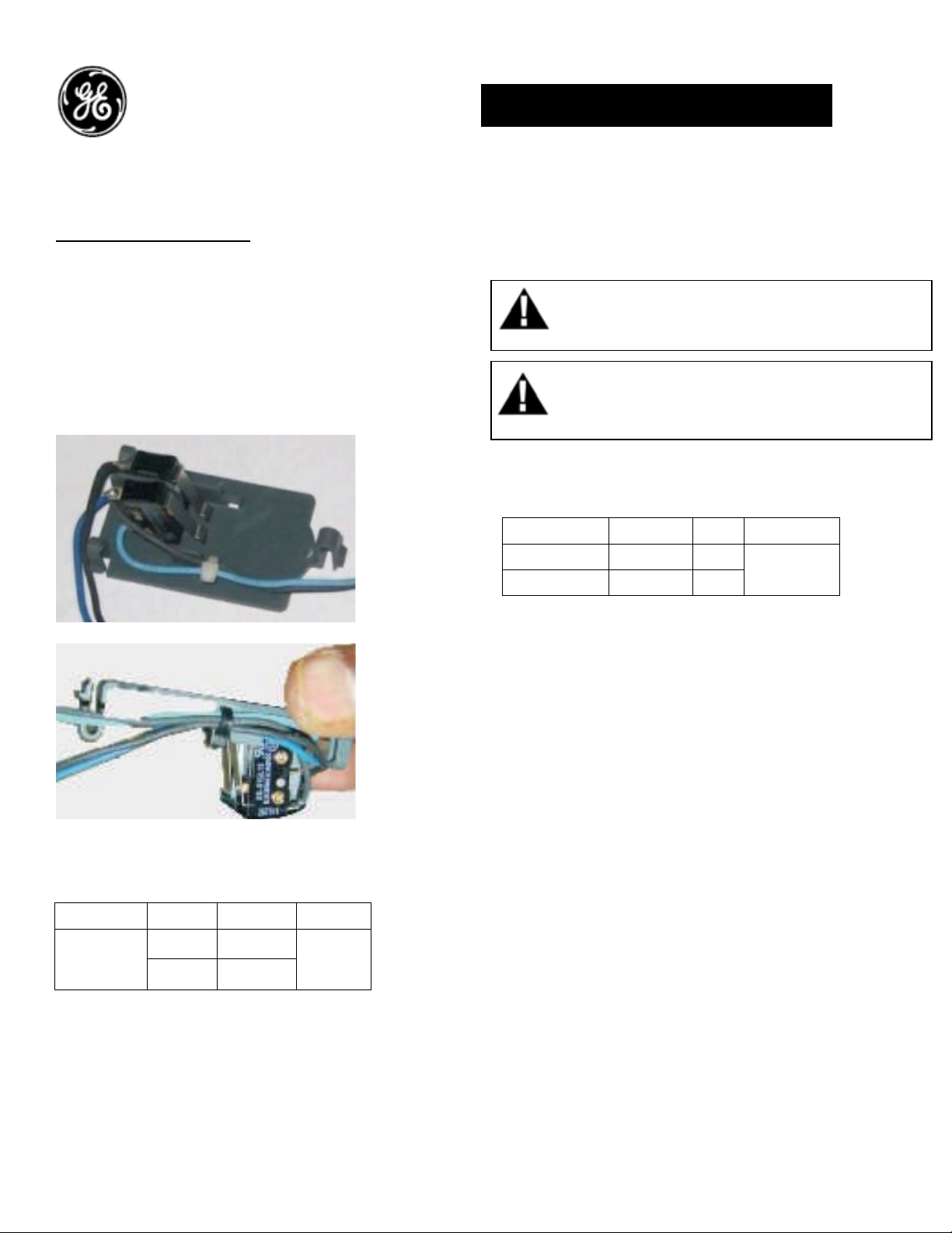
Coil Signaling Contacts:
Coil Signaling Contacts indicate the status of the
coil they are installed on. Coil Signaling Contacts
consists of two switches thus enables the status
of the coils thru trip unit and the secondary
disconnect. Status switch thru secondary
disconnect can be power rated or signal rated.
Status switch thru trip unit is a signal rated.
Table 1. Catalog Number and Ratings:
CSC, Power rated Contact:
AC Ratings
125Vdc 6A
250Vdc 6A
Cat no
GCSP1R
DEH-41420 Installation Instructions
EntelliGuard ®G Circuit Breaker
Accessories
Coil Signaling Contacts
WARNING: Before installing any accessories, turn the
breaker OFF, disconnect it from all voltage sources,
and discharge the closing spings.
AVERTISSEMENT: Avant d’installer tout accessoire,
mettre le disjoncteur en position OFF, le déconnecter
de toute tension d’alimentation , et décharger les
resorts d’armement
CSC, Signal rated Contact:
AC Ratings 125Vac 0.1A
Cat no
GCSP2R
DC Ratings 30Vdc 0.1A
Use the following procedure to install Release
Indication Contact accessory into the circuit
breaker.
1. Verify that the rating on the Release Indication
Contact identification plate matches the voltage
rating required for the application, as listed in
Table 1.
2. Turn the breaker off and discharge the closing
springs by depressing the OFF and ON buttons in
the sequence OFF-ON-OFF. Verify that the
breaker OFF-ON indicator shows OFF on a green
background and that the charge indicator shows
DISCHARGE on a white background. If installing
in a draw-out type breaker remove breaker from
adaptor (cassette) before continuing.
3. Loosen the 6 screws on front cover (fascia)
using a posidrive screw driver as shown in Fig 1.B
1
Page 2
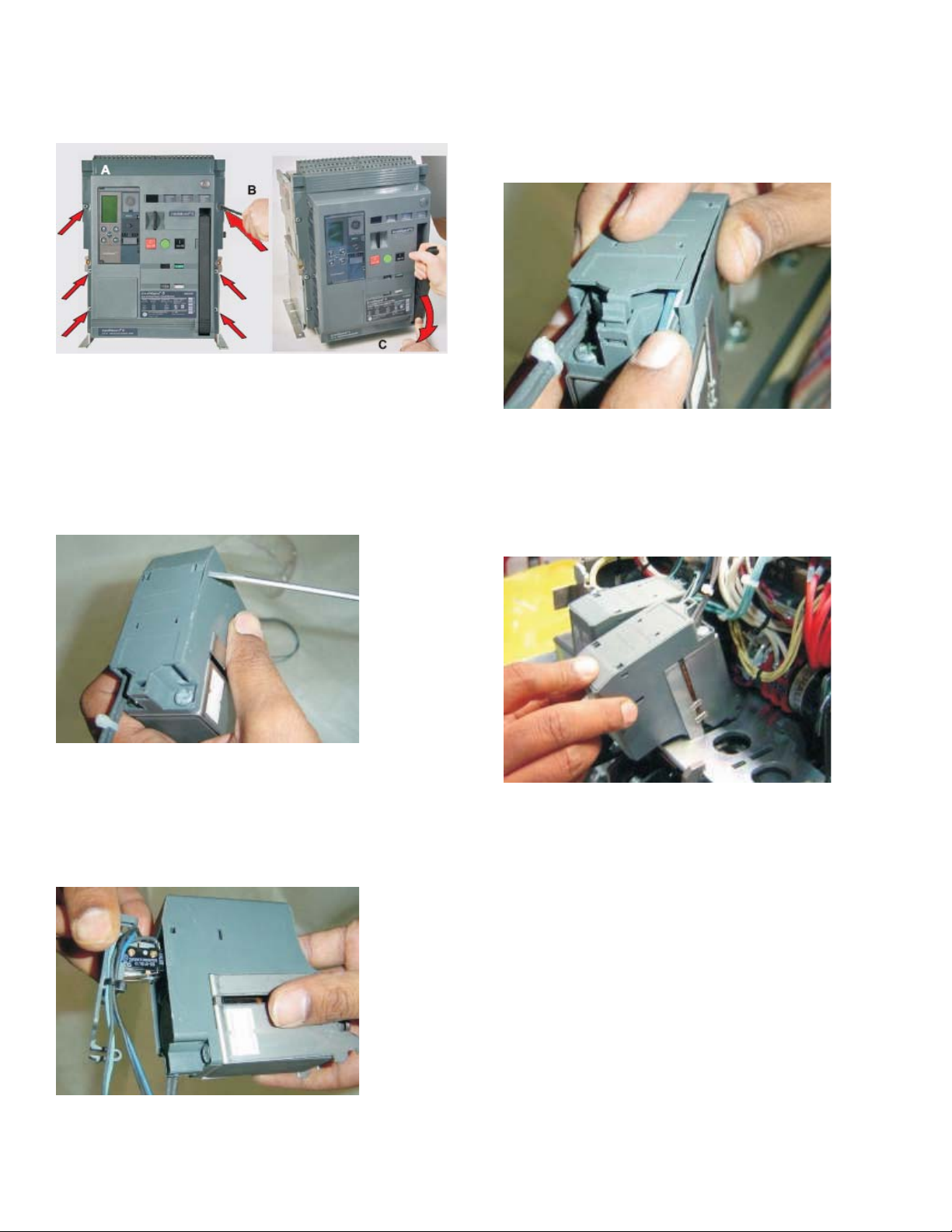
Rotate the charging handle down and slide the
front cover over the handle to remove the front
cover as shown in Fig. 1.C.
7. Guide the wires in the wire opening of the coil
housing as shown in Fig. 4. Press the cover and
ensure the 3 snaps are engaged with the
openings in the coil housing.
Figure 1. (A) Front Cover (B) Screw Removal (C) Handle
Rotation
4. Remove the existing coil from the mechanism.
5. Remove the coil cover by pressing the three
snaps as shown in Fig. 2.
Figure 2. Removing the existing cover
6. Align the new cover with Release Indication
Contacts on the coil as shown in Fig. 3.
Figure 4. Cover assembly
8. Tilt the coil forward and engage the front hooks
into the mechanism top support plate as shown
in the Fig. 5.
Figure 5. Assembly of coil
9. Plug the connector from the Release
Indication Contact cover with the connectors
from the harness of the trip unit as shown in Fig.6.
While connecting ensure the coils are connected
with the correct connectors from the harness
such as marked as ST1/UV1/CC/ST2&UV2 from
the respective coils.
Figure 3. Cover assembly
2
Page 3

Figure 6. Assembly of connector
7. Tilt the device backwards until the rear hooks
engage in the slots on the mechanism top
support plate as shown in the Fig. 7.
9. Assemble the connector plug from the coils
status switch cover to the terminal locations in
SD block B as shown in Fig. 9.
Figure 9. Assembly of connector plug
10. To reinstall the cover, rotate the charging
handle down and slide the front cover over the
handle to assemble the front cover to housing as
shown in Fig. 10.
Figure 7. Assembly of coil
8. Connect the input wire assembly plug to the
terminal locations in the SD A block of the
respective coil as shown in Fig. 8
Figure 8. Assembly of connector plug
Figure 10.
12. Ensure the fascia is aligned properly with the
trip unit and the pad lock features of the breaker.
. Fasten the 6 mounting screws of fascia with
13
the housing using a pozidrive screwdriver. Apply
torque of 6 Nm (4.42ft-lbs).
3
Page 4

Reference:
These instructions do not purport to cover all details or variations in equipment nor, to provide contingency to be met in connection
with installation, operation, or maintenance. Should further information be desired, or should particular problems arise which are not
covered sufficiently for the purchaser’s purposes, the matter should be referred to GE.
GE
41 Woodford Ave, Plainville, CT 06062
www.geelectrical.com
© 2009 General Electric Company
-
4
 Loading...