

Page 1
Introduction
Castel Lock kit:
The breaker key lock is an optional accessory,
which will keep the breaker in trip free state while
locked. Maximum 1 key of Castell type can be
used. All EntelliGuard Devices can be equipped
with one castell lock, that when fitted as
indicated.
Devices are found in two Variants:
1. Factory mounted mechanism:
The breaker/device is supplied off works with all
cams and screws allowing the user to mount a
separately acquired GE type lock kit.
2. Field mountable device:
A kit is supplied allowing the field mounting of the
locking mechanism and allowing the use of a lock
of the correct type purchased elsewhere
Catalog Number:
Catalog No Description
GBCASR Castell Lock Kit
Use the following procedure to install the Key
Interlock Key accessory into the circuit breaker.
1. Turn the breaker off and discharge the closing
springs by depressing the OFF and ON buttons in
the sequence OFF-ON-OFF. Verify that the
breaker OFF-ON indicator shows OFF and that the
charge indicator shows DISCHARGE. If installing
in a draw-out type breaker remove breaker from
adaptor (cassette) before continuing.
DEH-41376 Installation Instructions
EntelliGuard
Accessories
Castell lock Kit
WARNING: Before installing any accessories, turn
the breaker OFF, disconnect it from all voltage
sources, and discharge the closing spings.
AVERTISSEMENT: Avant d’installer tout accessoire,
mettre le disjoncteur en position OFF, le
déconnecter de toute tension d’alimentation , et
décharger les resorts d’armement
2. Turn the breaker off and discharge the closing
springs by depressing the OFF and ON buttons in
the sequence OFF-ON-OFF. Verify that the
breaker OFF-ON indicator shows OFF on a green
background and that the charge indicator shows
DISCHARGE on a white background. If installing
in a draw-out type breaker remove breaker from
adaptor (cassette) before continuing.
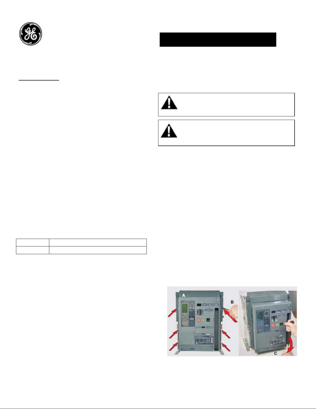
3. Loosen the 6 screws on front cover (fascia)
using a pozidrive screw driver as shown in Fig 1.B
Rotate the charging handle down and slide the
front cover over the handle to remove the front
cover as shown in Fig. 1.C
Figure 1. (A) Front Cover (B) ScrewRemoval (C) Handle
Rotation
®
G Circuit Breaker
1
Page 2
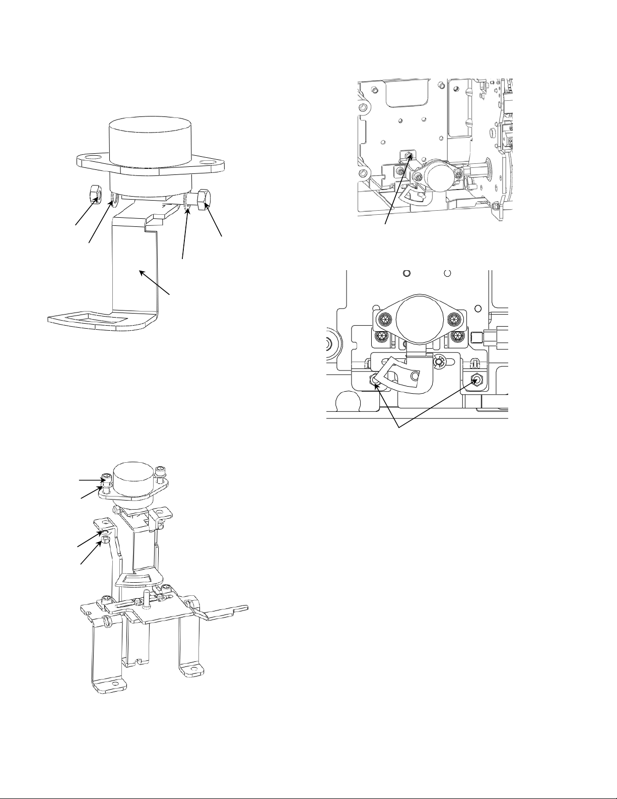
4. Fix the cam with the Castell lock with the screw
and nuts provided along with the kit as shown in
fig 2.
6. Fix the mounting bracket assembly in breaker
using the nuts provided as shown in fig 4a & 4b.
Nut
Washer
Washer
Cam
Screw
Fig 2.
5. Fix the Lock assy on the mounting Braket as
shown in fig 3.
Screw
Washer
Washer
Nut
Fig 3.
Fixing nut
Fig 4a
Fixing nut
Fig 4b
7. Using the supplied screws fit the cover onto
the Fascia
8. To reinstall the Fascia, rotate the charging
handle down and slide the fascia over the handle
to assemble the front cover to housing as shown
in Fig. 5.
9. Ensure the fascia is aligned properly with the
trip unit and the pad lock features of the breaker
10. Fasten the 6 mounting screws of fascia with
the housing using a pozidrive screwdriver. Apply
torque of 6 Nm (4.42 ft-lbs).
2
Page 3

y
Fig 5
Breaker key lock Operation:
Use the following procedure to operate the
padlock:
1. Depress the OFF pushbutton on the breaker
front Fascia and extend/pull the breaker padlock
lever to its' outer position.
2. With the padlock lever extended, rotate one or
more of the keys anticlockwise as shown in fig 6.
The key can then be removed thus locking the
breaker in its open position.
3. With padlock lever extended, insert the key and
rotate in clockwise to unlock.
These instructions do not purport to cover all details or variations in equipment nor, to provide contingency to be met in connection
with installation, operation, or maintenance. Should further information be desired, or should particular problems arise which are
not covered sufficientl
for the purchaser’s purposes, the matter should be referred to GE.
GE
41 Woodford Ave, Plainville, CT 06062
www.geelectrical.com
© 2009 General Electric Company
Fig 6
Fig 7 (Locked Condition)
-
3
 Loading...