

Page 1
Introduction
Carriage Position Switch Kit:
Carriage position switch indicates the breaker
status whether it is in the Disconnect, Test or
Connected positions of a draw out circuit breaker.
The Carriage Position Switch comes in two
options: one switch or two switches per position.
Electrical characteristics Carriage Position
Switch Contacts
Table 1. Ratings.
AC Ratings DC Ratings
Voltage Amps Voltage Amps
120V 10A 125V 0.5A
250V 10A 250V 0.25A
Contacts are Power Rated
Table2. Cat No.
GCPS1R 1 NO/1 NC per position
GCPS2R 2 NO/2 NC per position
The Switches are “change over switches” with NO,
NC & Com terminals. (Form C Contact).
DEH-41403 Installation Instructions
EntelliGuard ® G Circuit Breaker
Accessories
Carriage Position Switch Kit
WARNING: Before installing any accessories, turn the
breaker OFF, disconnect it from all voltage sources,
and discharge the closing spings.
AVERTISSEMENT: Avant d’installer tout accessoire,
mettre le disjoncteur en position OFF, le déconnecter
de toute tension d’alimentation , et décharger les
resorts d’armement
Use the following procedure to install the Position
Switch Kit accessory into the circuit breaker.
1. Verify that the rating and the catalogue on the
Position Switch Kit identification plate matches
the voltage rating required for the application,
as listed in Table 1
2. Before installing ensure the main power
sources are disconnected and no power to the
breaker main terminals
3. Rack out and remove the Breaker from
Cassette if it is installed
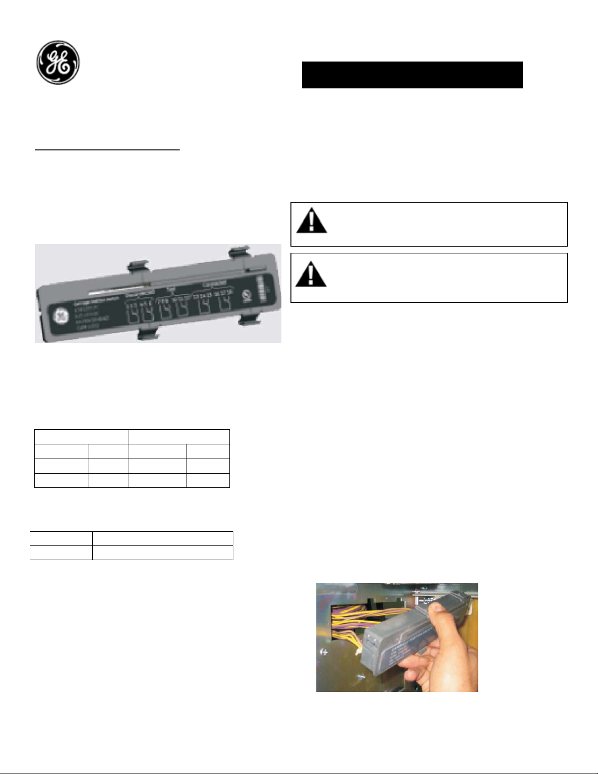
4. Insert the carriage position switch wires from
the opening from the inside of the cassette
and pull out as shown in Fig. 1
Figure 1. Wire insertion.
1
Page 2
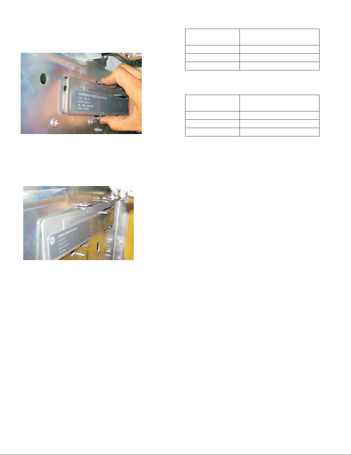
5. Slide & insert the switch assembly to engage
the cassette side sheet in the slot and push
towards the front as shown in Fig. 2
Figure 2. CPS assembly.
6. Push the complete assembly to come out side
of the cassette and the snap feature engages
with the cassette side sheet as shown in Fig.3.
Figure 3. CPS assembly
7. Ensure the assembly is firmly fitted and locked
down by the four snaps features.
8. Check functionality of carriage position switch
by racking in the breaker and racking out the
breaker and confirming changeover of switch
as specified in table 3 & 4.
9. Complete the wiring with the equipment.
Table 3: Switch terminals for cat GCPS1R
Continuity between
Breaker Position
terminals
Disconnected D11-D14
Test D31-D34
Connected D51-D54
Table 4: Switch terminals for cat GCPS2R
Continuity between
Breaker Position
terminals
Disconnected D11-D14 & D21-D24
Test D31-D34 & D41-D44
Connected D51-D54 & D61-D64
2
Page 3

Reference:
Carriage Position Switch Kit Connection Scheme:
These instructions do not purport to cover all details or variations in equipment nor, to provide contingency to be met in connection
with installation, operation, or maintenance. Should further information be desired, or should particular problems arise which are not
covered sufficiently for the purchaser’s purposes, the matter should be referred to GE.
GE
41 Woodford Ave, Plainville, CT 06062
www.geelectrical.com
© 2009 General Electric Company
-
3
 Loading...