

Page 1
GE Consumer & Industrial
Power Protection
Instruction sheet
Gebrauchsanleitung Instrukcja montażu
DEH-41 451
EntelliGuard G
B1 B2B3
Priority
Cable Interlock (Fixed Breaker)
Bowdenzugverriegelung (Festeinbauschalter)
Blokada mechaniczna (dla wyłączników stacjonarnych)
Read this Instruction sheet and please retain for
future use.
WARNING
During operation the device described in this
Instruction sheet is connected to high and potentially
dangerous voltages.
Only qualified personnel are allowed to install,
commission, maintain or modify this device in
accordance with relevant safety requirements.
Non Compliance with these requirements could result
in damage to property and/or severe injury to
personnel.
Before installing any accessories, turn the breaker OFF,
disconnect it from all voltage sources, and discharge
the closing springs.
Lesen Sie bitte diese Gebrauchsanleitung und
bewahren Sie sie bitte griffbereit auf.
WARNUNG
Während des Betriebes ist das in dieser
Gebrauchsanleitung beschriebene Gerät an hohe,
potenziell gefährliche Spannungen angeschlossen.
Montage, Inbetriebnahme, Wartung, Änderung und
Nachrüstung dieser Geräte dürfen deshalb nur von
qualifiziertem Fachpersonal unter Befolgung der
einschlägigen Sicherheitsvorschriften ausgeführt
werden.
Die Nichtbeachtung dieser Erfordernisse kann hohe
Sachschäden und / oder schwere Körperverletzungen
zur Folge haben.
Vor der Installation jeglicher Zubehörteile schalten Sie
bitte den Leistungsschalter aus, trennen ihn von jeder
Spannungsquelle und entspannen Sie die
Antriebsfedern.
Prosimy o dokładne przeczytanie instrukcji i
zachowanie jej na przyszłość.
OSTRZEŻENIE
Aparaty opisane w tej instrukcji podczas eksploatacji
są podłączone do wysokich, potencjalnie
niebezpiecznych napięć.
Instalację, uruchomienie, konserwację i modyfikację
aparatów może wykonywać tylko odpowiednio
przeszkolony personel, zgodnie z wymogami
bezpieczeństwa.
Nieprzestrzeganie powyższych zasad może
doprowadzić do strat materialnych i/lub poważnych
obrażeń personelu.
Przed montażem jakiegokolwiek wyposażenia lub
części zamiennych należy otworzyć wyłącznik,
odłączyć wszystkie źródła zasilania i zluzować
(rozbroić) sprężyny zamykające.
GE imagination at work
DEH-41 451 ed.00 01/10
Page 2
EntelliGuard G
Deutsch Polski
General
Mechanically Interlocked Breakers
Many Low Voltage Installations have multiple
power sources that are used in many different
configurations. The power sources are required to
supply the installation simultaneously, alternatively
or in a certain logical combinations of both.
Allgemeines
Mechanisch verriegelte Leistungsschalter
Viele Niederspannungsinstallationen haben
mehrfache Versorgungsquellen und sind in vielen
verschiedenen Konfigurationen verschaltet. Die
Versorgungsquellen versorgen die Installationen
teils gleichzeitig oder abwechselnd alternativ oder
unter Sicherheitsaspekten mit beiden Möglichkeiten
als Kombination.
Cable Interlock (Fixed Breaker)
Bowdenzugverriegelung (Festeinbauschalter)
Blokada mechaniczna (dla wyłączników stacjonarnych)
The EntelliGuard G™ Power Circuit Breaker can be
used to protect these Power supplies and be
electrically and mechanically interlocked to provide
the necessary logic. The mechanical interlocks are
available for fixed or draw out circuit breakers,
enabling the direct interlocking of the breakers,
mounted side by side or stacked.
The device has two parts; the first a factory
mounted component fitted to the breaker when in
Fixed Pattern or the cassette when used in draw out
mode. Two or more specially designed field
mountable cables available in lengths of 1,0, 1,6,
2,0, 2,5, 3,0, 3,5 and 4,0 meter being the second.
Any combination mode (fixed or draw out), current
rating, number of poles or envelope size can be
interlocked. The interlocking systems are available
in one configuration for 2 breakers and in three
others for 3 breakers.
Die EntelliGuard G™ Leistungsschalter können als
Schutz für diese Versorgungsquelle eingesetzt und
elektrisch und mechanisch verriegelt werden, um
die erforderliche Schutzlogik sicherzustellen. Die
mechanischen Verriegelungen sind für Festeinbauoder Ausfahrtechnik-Leistungsschalter verfügbar
und ermöglichen die direkte Verriegelung der
Leistungsschalter, die seitlich oder übereinander
zueinander montiert werden können.
Das System hat zwei Teile; das erste als
Werkseinbaukomponente am Leistungsschalter in
Festeinbautechnik angebaut oder im
Einschubträger beim Ausfahrtechnikmodus. Zwei
oder auch mehrere speziell konstruierte und
vorortmontierbare Bowdenzüge, verfügbar in den
Längen von 1, 1.6, 2, 2.5, 3, 3.5 und 4 Meter sind das
zweite Teil.
Jede Kombinationsart (Festeinbau- oder
Ausfahrtechnik), Stromwert, Anzahl der Pole oder
Baugrößen können verriegelt werden. Die
Verriegelungssysteme sind in einer
Kombinationskonfiguration für 2 Leistungsschalter
und in drei Varianten für 3 Leistungsschalter
verfügbar.
Informacje ogólne
Wyłączniki połączone blokadą
mechaniczną
W wielu instalacjach niskiego napięcia występuje
kilka źródeł zasilania, używanych w różnych
konfiguracjach. Zależnie od potrzeb wymagane jest
zasilanie z kilku źródeł jednocześnie, zamiennie lub
w określonych logicznych kombinacjach tych
dwóch metod.
Wyłączniki EntelliGuard G™ stosowane do
zabezpieczania kilku źródeł zasilania mogą być
sprzężone blokadami elektrycznymi lub
mechanicznymi w celu zapewnienia wymaganych,
logicznych sekwencji załączania. Blokady
mechaniczne są produkowane dla wyłączników
stacjonarnych lub wysuwnych, umożliwiając
bezpośrednie sprzęganie wyłączników ustawionych
obok siebie lub jeden nad drugim.
Blokada składa się z dwóch zasadniczych
elementów; jednym z nich jest mechanizm
mocowany fabrycznie w wyłączniku stacjonarnym
lub podstawie (kasecie) wyłącznika wysuwnego.
Drugim elementem blokady są cięgna (dwa lub
więcej) dostępne w różnych długościach: 1,0, 1,6,
2,0, 2,5, 3,0, 3,5 i 4,0 metry, podłączane w miejscu
instalacji wyłączników.
Blokadą mechaniczną można połączyć różne
kombinacje wyłączników (stacjonarnych lub
wysuwnych), o różnych prądach znamionowych,
ilości biegunów lub wielkości obudowy. Blokady są
produkowane w jednej wersji służącej do
połączenia 2 wyłączników oraz w trzech różnych
wersjach dla 3 wyłączników.
Interlocking of Multiple Breakers
Mechanical interlocks are optional devices available
for beakers in a fixed or Drawout pattern. These
enable the interlocking of 2 or 3 breakers mounted
side by side or stacked.
These devices have two parts : The first a factory
mounted component is fitted to the chassis when in
Fixed pattern or to the cassette when used in
drawout mode. Two or more specially designed ,
field mountable cables being the second.
Any combination (fixed or drawout), current rating,
number of poles or envelope size can be
interlocked. Systems are available in one
configuration for 2 breakers and in three variants
for 3 breakers.
Fig. 3.8
“A” cm
Top
Circuit
Breaker
Bottom
Circuit
Breaker
Mehrfache Schalterverriegelung
Mechanische Verriegelungen sind optionale
Zubehörteile für Leistungsschalter in Festeinbauund Ausfahrtechnik. Diese ermöglichen die
gegenseitige Verriegelung von 2 oder 3
Leistungsschaltern, übereinander oder seitlich
zueinander montiert.
Sie besteht aus 2 grundsätzlichen Teilen: Die erste
werkseitig montierte Komponente ist am
Leistungsschalter oder bei Einschubtechnik am
Einschub befestigt. Zwei oder mehrere spezielle
Bowdenzüge bilden den zweiten Teil und werden
Vorort montiert.
Jede Kombination (Festeinbau- oder
Ausfahrtechnik), Stromwerte, Polanzahl oder
Baugrößen können verriegelt werden, jeweils mit 2
oder auch 3 Schaltern.
Fig. 3.8: Vertical Mounting Dimensions
Abb. 3.8: Vertikale Montage-Abmessungen
Fot. 3.8: Wymiary dla zamocowania pionowego
Fig. 3.9: Horizontal Mounting Dimensions
Abb. 3.9: Horizontale Montage-Abmessungen
Fot. 3.9: Wymiary dla zamocowania poziomego
Fig. 3.9
1
Circuit
Breaker
“A” cm
2
Circuit
Breaker
Blokady między wyłącznikami
Blokady mechaniczne sprzęgające wyłączniki są
opcjonalnym wyposażeniem dla aparatów w wersji
stacjonarnej lub wysuwnej. Umożliwiają sprzężenie
2 lub 3 wyłączników umieszczonych poziomo obok
siebie lub pionowo jeden nad drugim.
Blokady składają się z dwóch elementów:
mechanizmów blokujących montowanych
fabrycznie na obudowach wyłączników
stacjonarnych lub do podstaw wyłączników
wysuwnych. Drugim elementem składowym są 2
lub 3 cięgna łączące mechanizmy blokujące; cięgna
są zakładane w miejscu instalacji.
Blokadą można połączyć dowolne wyłączniki
(stacjonarne lub wysuwne) o dowolnych prądach
znamionowych, ilości biegunów lub wielkości
obudowy. Mechanizmy blokad są produkowane w
10 cm (Min.) Cable
02
14 cm (Min.) Cable
Page 3
English Deutsch
1 of 2 breaker interlock (Type A)
With the 1 of 2 interlock in use, if one breaker is ON
the second breaker cannot be turned ON. There is
no priority, if any of the 2 breakers is ON the other
cannot be turned ON. The second breaker can be
charged and ready to close, to enable a fast
transition from one to the other breaker.
1 von 2 Schalterverriegelung (Typ A)
Mit der 1 von 2 Verriegelung kann bei einem
Leistungsschalter in EIN-Stellung der zweite
Leistungsschalter nicht aktiviert werden. Es gibt
keinen Vorrang, sowie sich einer der zwei
Leistungsschalter in EIN-Stellung befindet, kann der
andere Schalter nicht EIN-geschaltet werden. Der
zweite Leistungsschalter kann gespannt und in die
"Schliessbereit"-Stellung gebracht werden, damit
ein schnelleres Umschalten von einem zum
anderen Leistungsschalter erfolgen kann.
B1 B2
G
B1
B2
0
0
I
0
0
I
Type A
DEH-41 451
jednej wersji dla 2 wyłączników oraz w trzech
wersjach dla 3 wyłączników.
Blokada "1 z 2 wyłączników" (typ A)
Gdy dwa wyłączniki są sprzężone blokadą "1 z 2"
wtedy tylko jeden z nich może być zamknięty.
Żaden z wyłączników nie ma pierwszeństwa
(priorytetu); jeśli którykolwiek z wyłączników jest
zamknięty - drugiego z nich nie można zamknąć.
Drugi z wyłączników można zazbroić i przygotować
do załączenia, aby umożliwić szybkie przełączenie.
1 of 2 Breaker
Only 1 from 2 breaker can be closed.
1 von 2 Leistungsschaltern
Nur einer von 2 Schaltern kann geschlossen sein.
1 z 2 wyłączników
Tylko 1 z 2 wyłączników może być zamknięty.
EntelliGuard G
Cable Interlock
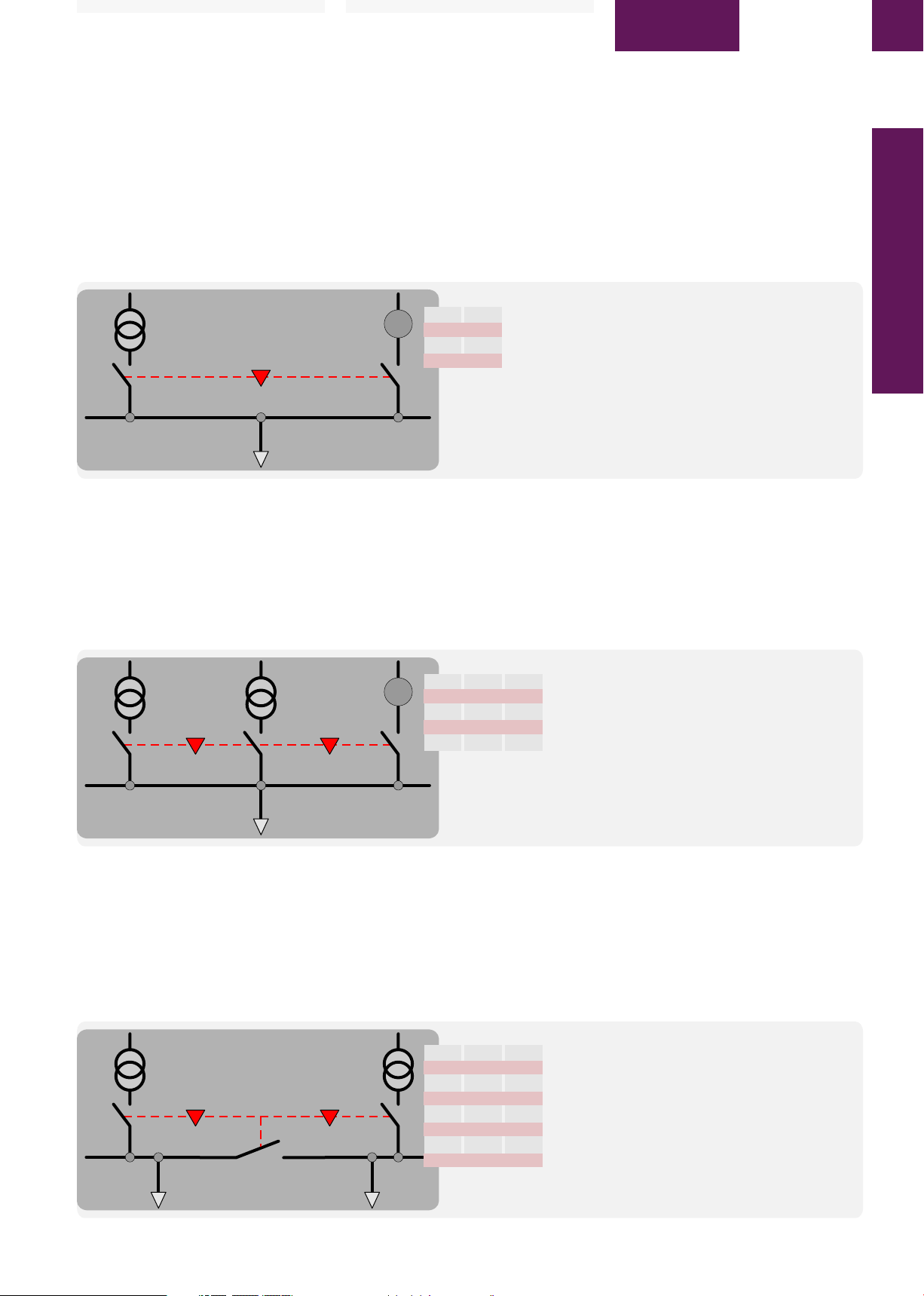
1 of 3 breaker interlock (Type B)
With the 1 of 3 interlock in operation, if one breaker
is ON the other 2 breakers cannot be turned ON.
There is no priority, if any of the 3 breakers is ON the
others are prevented. The breakers that are not ON
can be charged and ready to close, to enable a fast
transition from one to the other breaker.
B1 B3B2
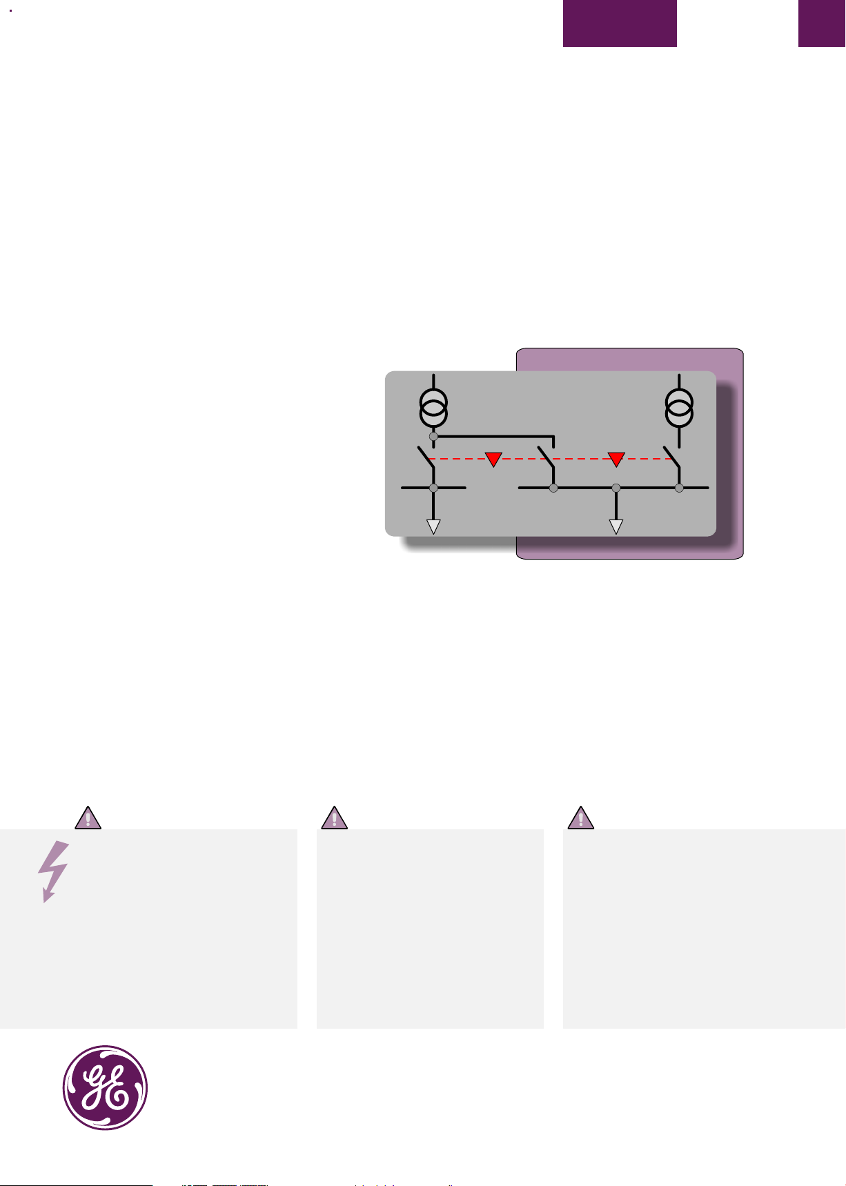
2 of 3 breaker interlock (Type C)
With the 2 of 3 interlock in operation, one breaker is
always OFF. However, 1 or 2 of the other breakers
can be ON.
There is no priority, if any 2 of the 3 breakers are
ON the remaining is prevented from being turned
ON. The breaker which is not ON can be charged
and ready to close, to enable a fast transition.
B1 B2B3
1 von 3 Schalterverriegelung (Typ B)
Mit der 1 von 3 Verriegelung können, wenn ein
Leistungsschalter in EIN-Stellung ist, die anderen
zwei Leistungsschalter nicht aktiviert werden. Es
gibt keinen Vorrang, sowie sich einer der drei
Leistungsschalter in EIN-Stellung befindet, können
die anderen Schalter nicht betätigt werden. Die
anderen Leistungsschalter können aber gespannt
und in die "Schliessbereit"-Stellung gebracht
werden, damit ein schnelleres Umschalten von
einem zum anderen Leistungsschalter erfolgen
kann.
1 of 3 Breaker
B1
B2
0
G
0
I
0
0
I
0
0
Type B
2 von 3 Schalterverriegelung (Typ C)
Mit der 2 von 3 Verriegelung ist 1 Leistungsschalter
immer in AUS-Stellung. Wie auch immer, können
gleichzeitig 1 oder 2 Leistungsschalter in EINStellung sein.
Es gibt keinen Vorrang, wenn alle 2 der 3
Leistungsschalter eingeschaltet sind, dann ist der
verbleibende Schalter nicht einschaltbar. Der
Leistungsschalter, der nicht in EIN-Stellung ist, kann
gespannt und in die "Schliessbereit"-Stellung
gebracht werden, damit ein schneller
Umschaltvorgang vorgenommen werden kann.
B1
B2
0
0
I
0
0
I
0
0
0
I
I
0
I
I
Type C
3 power supplies (generator or transformers feeding the same busbar,
B3
but parallel operation is prevented.
0
Only 1 from 3 breaker can be closed.
0
1 von 3 Leistungsschaltern
0
3 Versorgungen (Generator oder Trafos) versorgen den gleichen
I
Stromkreis, Parallelbetrieb wird verhindert.
Nur einer von 3 Schaltern kann geschlossen sein.
1 z 3 wyłączników
3 źródła zasilania (agregat prądotwórczy lub transformatory zasilające
te same szyny,) jednak praca równoległa jest zabroniona
Tylko 1 z 3 wyłączników może być zamknięty
2 of 3 Breaker
2 bus sections can be powered by a single transformer (B3 closed),
B3
..or by both transformers (B3 open)
Any 1 from 3 breakers can be closed.
0
Any 2 from 3 breakers can be closed.
0
2 von 3 Leistungsschaltern
0
2 Schaltkreise können von einem Trafo versorgt werden
I
(B3 geschlossen),..oder von beiden Trafos (B3 offen)
Jeder einzelne von 3 Schaltern kann geschlossen sein.
I
Jeweils zwei von 3 Schaltern können gleichzeitig geschlossen sein.
I
2 z 3 wyłączników
0
2 sekcje szyn można zasilać z jednego transformatora (B3 zamknięty),
lub z obydwu transformatorów (B3 otwarty)
1 dowolny wyłącznik spośród 3 może być zamknięty
2 dowolne wyłączniki spośród 3 mogą być zamknięte
Blokada "1 z 3 wyłączników" (typ B)
Gdy wyłączniki są sprzężone blokadą "1 z 3"
wówczas jeśli jeden z nich jest zamknięty (ON)
pozostałych 2 nie można zamknąć. Żaden z
wyłączników nie ma pierwszeństwa (priorytetu); jeśli
którykolwiek z 3 wyłączników jest zamknięty (ON)
zamknięcie pozostałych nie jest możliwe. Wyłączniki
otwarte można zazbroić i przygotować do
załączenia, aby umożliwić szybkie przełączanie.
Blokada "2 z 3 wyłączników" (typ C)
Gdy wyłączniki są sprzężone blokadą "2 z 3"
wówczas zawsze jeden jest otwarty.. Jeden lub dwa
pozostałe wyłączniki mogą być zamknięte (ON).
Żaden z wyłączników nie ma pierwszeństwa
(priorytetu); jeśli którekolwiek 2 z 3 wyłączników
są zamknięte - pozostałego nie można
zamknąć. Wyłącznik który aktualnie nie jest
zamknięty można zazbroić i przygotować do
załączenia, aby umożliwić szybkie przełączanie.
03
Page 4
EntelliGuard G
Deutsch Polski
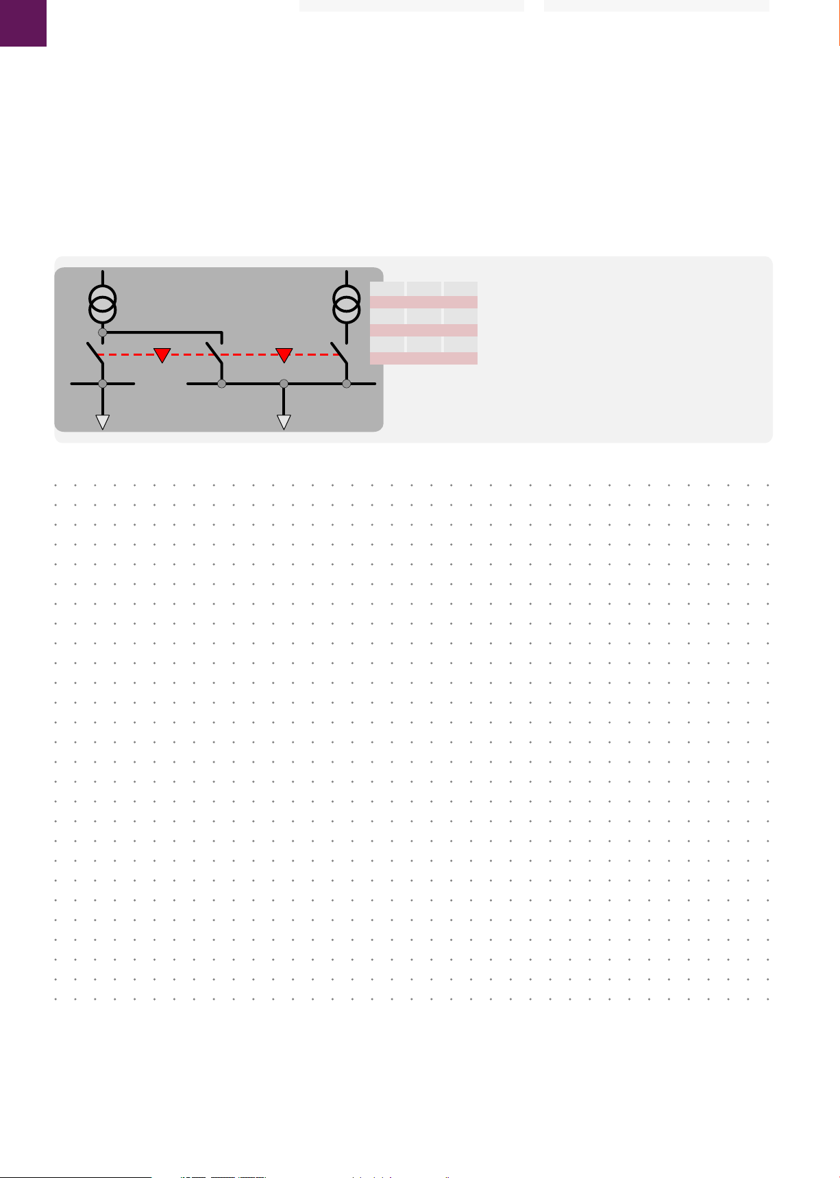
2 of 3 breaker interlock with priority (Type D)
With the 2 of 3 interlock in operation, one of the
three breakers has priority over both the others,
hence when the priority breaker is ON the other 2
MUST be OFF. Also entailing that when the priority
breaker is OFF the other 2 breaker can be turned
ON. This is typically used for a main-tie-main
arrangement.
B1 B2B3
2 von 3 Verriegelung mit Vorrang (Typ D)
Mit der 2 von 3 Verriegelung mit Vorrang besitzt
einer der drei Leistungsschalter Schaltvorrang vor
den anderen beiden Schaltern. Wenn der
Vorrangschalter in EIN-Stellung ist , müssen die
anderen zwei AUS sein. Dies bedeutet auch, dass,
wenn der Vorrangschalter AUS ist, die anderen zwei
Schalter auch beide gleichzeitig eingeschaltet sein
können. Dies ist die typische Anwendung für eine
Koppelschalter-Hauptschalter-Anordnung.
2 of 3 Breaker with Priority
2 normal power supply not set in parallel.
B3
1 power supply may assist the priority circuit.
Breaker B1 and/or B2 can be closed only if B3 is open.
0
Breaker B3 can only be closed if B1 and B2 are both open.
0
2 von 3 Leistungsschaltern mit Vorrang
0
2 normale Stromversorgungen nicht parallel geschaltet.
I
1 Stromversorgung kann den Vorrangstromkreis unterstützen.
Schalter B1 und/oder B2 können geschlossen werden, wenn B3 offen ist.
0
Schalter B3 kann nur geschlossen werden, wenn B1 und B2 offen sind.
2 z 3 wyłączników z pierwszeństwem
2 linie zasilania podstawowego nie pracujące równolegle
1 linia zasilająca może wspomagać zasilanie priorytetowe
Wyłącznik B1 i/lub B2 mogą być zamknięte gdy B3 jest otwarty
Wyłącznik B3 może być zamknięty jeśli B1 i B2 są otwarte.
Priority
B1
B2
0
0
I
0
0
I
0
0
I
I
Type D
Blokada "2 z 3 wyłączników z pierwszeństwem"
(typ D)
Gdy wyłączniki są sprzężone blokadą "2 z 3 z
pierwszeństwem" wówczas jeden z trzech
wyłączników posiada pierwszeństwo (priorytet),
dlatego gdy wyłącznik priorytetowy jest zamknięty
(ON) pozostałe dwa MUSZĄ być otwarte (OFF).
Oznacza to również, że gdy wyłącznik priorytetowy
jest otwarty (OFF) wówczas pozostałe dwa mogą
być zamknięte (ON). Takie rozwiązanie jest zwykle
stosowane w układzie "sieć-sprzęgło-sieć".
These instructions do not purport to cover all details
or variations in equipment nor, to provide
contingency to be met in connection with
installation, operation, or maintenance. Should
further information be desired, or should particular
problems arise which are not covered sufficiently
for the purchaser's purposes, the matter should be
referred to GE.
04
Page 5
English Deutsch
DEH-41 451
EntelliGuard G
Installation Instruction of Cable Interlocks (Fixed Breaker)
Installationsangaben zur Bowdenzugverriegelung (Festeinbauschalter)
Instrukcja montażu blokad mechanicznych (dla wyłączników stacjonarnych)
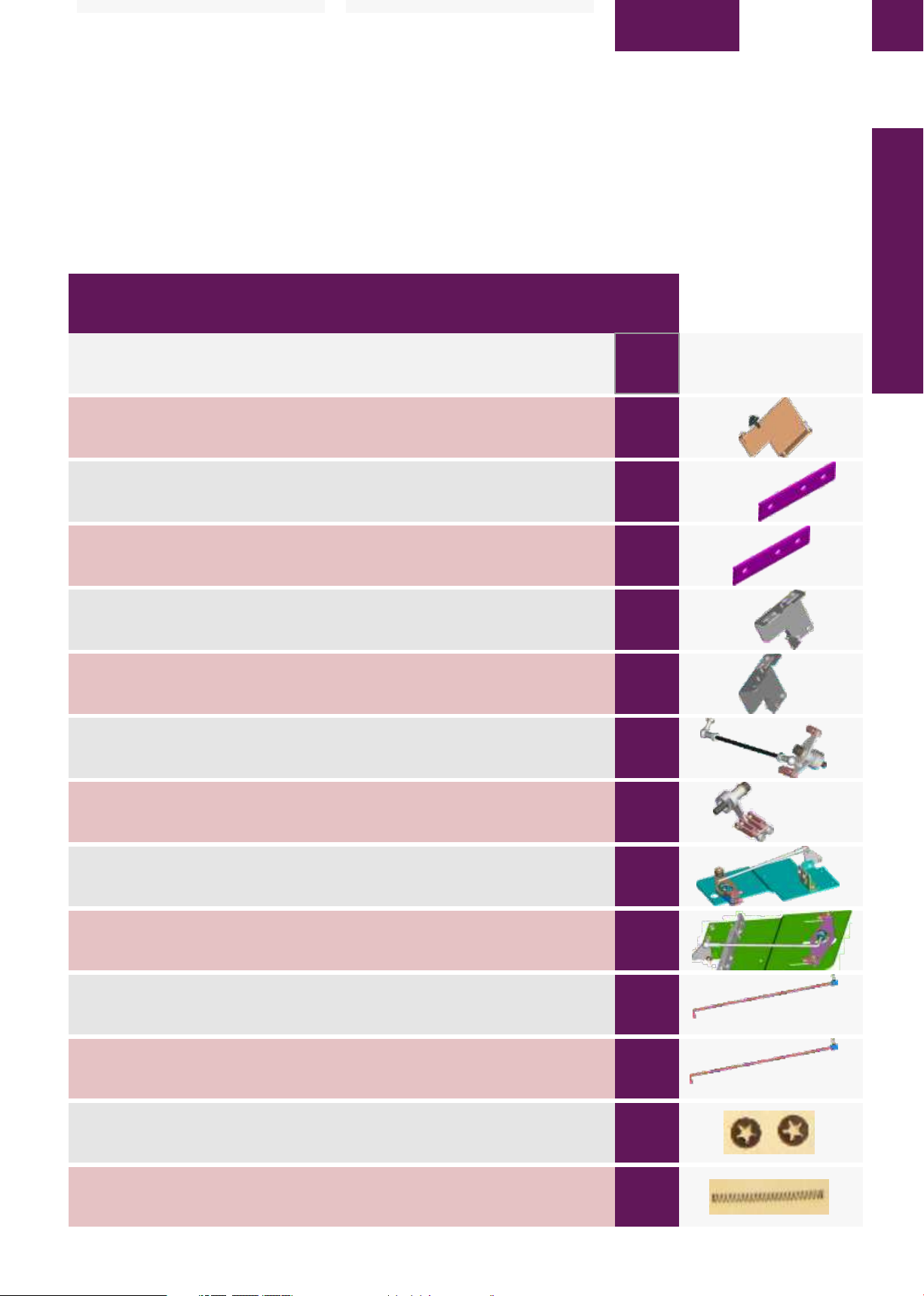
Part no Description Quantity per Kit
Teile Nr. Beschreibung Menge pro Bausatz
Nr kat. Opis Ilość w kpl.
Product / Produkt / G12FAD G13FB G13FC G13FDT
Type / Typ / Typ
10 102 300 G1 F/I Breaker Pivot BKT ASSY 1 1 1 1
10 102 262 P1 Spacer, LH-RH, Fixed INT, GACB 4mm thick 1 2 2 2
Produkt
A B C D
_Schalter Lagerpunkt
F/I Wspornik przegubu
Abstandshalter 4mm dick
Wkładka dystansowa, LH-RH, Stacjon. INT, GACB grubość 4mm
ITEM
ZIFFER
ELEMENT
1
2
Image
Bild
Rysunek
Cable Interlock
10 102 262 P2 Spacer, LH-RH, Fixed INT, GACB 2mm thick 1 2 2 2
10 102 299 G1 R.H. Side plate fixed assm 1 - - -
10 102 306 G1 F/I Cable BKT assm (type B), GACB - 1 1 1
10 102 296 G1 ASSY of fixed & F1, F2, F3 1 - - -
10 102 301 G1 F/I Drive lever assm- F1, F2, F3 - 1 1 1
10 102 307 G1 F/I BKT LH assm (type B), GACB - 1 - 1
10 102 309 G1 LH Side plate ASSY (type-C) - - 1 -
Abstandshalter 2mm dick
Wkładka dystansowa, LH-RH, Stacjon. INT, GACB grubość 2mm
Seitenplatte
Płyta z prawej strony dla wył-ka stacjonarnego
_(Typ B), GACB
F/I Wspornik cięgna (typ B), GACB
trans-
Einheit
Mechanizm dla wył-ków stacjon. i wysuwn. - F1, F2, F3
Antriebshebel
F/I Zespół dźwigni napędowej - F1, F2, F3
_(Typ B), GACB
F/I Wspornik z lewej strony (typ B), GACB
Seitenplatte (Typ C)
Płyta boczna z lewej strony (typ C)
3
4
5
6
7
8
9
10 102 489 G1 F/I # Pack RH drive ROD (F1-3P) 1 - - -
Übertragungsstange
F/I # Drążek napędowy z prawej strony (F1-3P)
10 102 491 G1 # Pack drive ROD F1 (1/3 & 2/3) - 1 1 1
Übertragungsstange
# Drążek napędowy F1 (1/3 i 2/3)
70 002 965 M5 Push on fixing- RS 172-341 4 4 4 4
Klemmscheiben
Śruba mocowania wciskanego - RS 172-341
LLY 11G C026 Cable return spring 1 2 2 2
Bowdenzugfeder
Sprężyna powrotna dla cięgna
10
11
12
13
05
Page 6

Deutsch Polski
EntelliGuard G
Instructions for Cable Interlocks (Fixed Breaker) (done at factory)
Angaben zur Bowdenzugverriegelung (Festeinbauschalter) (Fabrikationsmontage)
Instrukcja montażu blokad mechanicznych (dla wyłączników stacjonarnych) (wykonywany fabrycznie)
STEP 1 – MIDDLE PIVOT BRACKET ASSEMBLY
COMMON FOR ALL TYPES
- 1a. Remove M6 bolt and washers supplied with
ITEM 1(Items see page 5) and secure for reuse.
- 1b. Remove the special screw for Envelope 3
- 1c. Assemble ITEM 1 by inserting from bottom of
the breaker. The breaker may needs to be tilted
towards the backside to access the bottom. Locate
the Rivet on the ITEM 1 in the guide hole of the front
housing of breaker.
- 1d. Align left hole in the bracket with mounting
hole in the front housing, and then tighten the M6
bolt with washer from the front of the breaker.
Tighten to 7-9Nm.
Fig. 1a
C
A
_new image needed
B
A: M6 Bolt see instruction 1a
A: M6 Schraube siehe Hinweise 1a
A: Śruba M6, patrz: instrukcja 1a
Schritt 1 - Mittlere Halterungsmontage
Für alle Typen gleich:
- 1a. Entfernen Sie die mit ZIFFER 1 (Ziffern siehe
Seite 5) gelieferten M6 Schrauben und Scheiben und
verwenden Sie sie später wieder.
1b. Entfernen Sie die spezielle Schraube für
Baugröße 3.
- 1c. Fügen Sie die ZIFFER 1-Teile, durch
Anbringung von unten an den Leistungsschalter,
zusammen. Der Leistungsschalter sollte auf die
Rückseite gekippt werden, um die Unterseite
zugänglich zu haben. Platzieren Sie den Nietbolzen
nach ZIFFER 1 zum Führungsloch in dem Gehäuse
des Leistungsschalters.
- 1d. Nun folgt das linksbündiges Angleichen des
Loches in der Halterung mit der
Befestigungsbohrung in dem Vordergehäuse und
Festschrauben der M6 Schraube mit Scheibe von
der Vorderseite des Leistungsschalters.
Drehmoment 7-9Nm.
Fig. 1b
B
A
1
KROK 1 – MONTAŻ ŚRODKOWEGO
WSPORNIKA PRZEGUBOWEGO
WSPÓLNY DLA WSZYSTKICH TYPÓW
BLOKAD
- 1a. Usunąć śrubę M6 i podkładki dostarczone z
ELEMENTEM 1 (Elementy – patrz: str. 5) i zachować
do ponownego użycia.
- 1b. Usunąć specjalną śrubę dla obudowy o
wielkości 3
- 1c. Zamocować ELEMENT 1 wkładając od dołu
wyłącznika. Konieczne może być przechylenie
wyłącznika do tyłu aby uzyskać dostęp do
wyłącznika od spodu. Założyć nit na ELEMENT 1 w
otworze prowadzącym przedniej ściany wyłącznika.
- 1d. Wyrównać otwór we wsporniku z otworem
montażowym w przedniej ścianie obudowy,
następnie dokręcić śrubę M6 z podkładką od przodu
wyłącznika. Dokręcić momentem 7-9 Nm.
Fig. 1c
- see instruction 1d
- siehe Hinweise 1d
- patrz: instrukcja 1d
B: Screw see instruction 1b
B: Schraube siehe Hinweise 1b
B: Śruba, patrz: instrukcja 1b
C: Rivet see instruction 1c
C: Niet siehe Hinweise1c
C: Nit, patrz: instrukcja 1c
STEP 2 - RH SIDE ASSEMBLY
For TYPE A
- 2a. Remove M6 bolt, nut and washers supplied
with ITEM 4 and secure for reuse.
- 2b. Place ITEM 2 and 3 behind ITEM 4 and clamp
ITEM 4 using M6 screws along with washers and
nut. Use one quantity each of ITEM 2 and 3 for
Envelope 1 and 3. Use one quantity of only ITEM 3
for Envelope 2. Tighten to 9-11Nm at 2 locations as
shown fig.2a.
- 2c. Assemble ITEM 6 using M8 screws and
washers supplied loose along with ITEM 6 as shown
fig. 2a. Tighten to 24-28Nm.
- 2d. Remove M5 Nut and Lock washer comes with
bottom ball joint and insert Bottom ball joint
threaded end into triangular link as shown in fig.2a.
Tighten back M5 Nut lock washer to 5-7Nm.
For TYPE B,C and D
- 2e. Remove M6 bolt, nut and washers supplied
with ITEM 5 and secure for reuse.
- 2f. Place ITEM 2 and 3 behind ITEM 5 and clamp
ITEM 5 using M6 screws along with washers and
nut. Use one quantity each of ITEM 2 and 3 for
Envelope1 and 3. Use one quantity of only ITEM 3
06
A: Item 1
A: ZIFFER 1
A: Element 1
B: Guide hole see instruction 1c
B: Führungsloch siehe Hinweise 1c
B: Otwór prowadzący, patrz: instrukcja 1c
SCHRITT 2 - Rechte Seite Zusammenbau
Für Typ A
- 2a. Entfernen Sie M6-Schraube, Mutter und
Scheiben geliefert nach ZIFFER 4 (Seite 5) und
verwenden Sie sie später wieder.
- 2b. Platziere ZIFFER 2 & 3 hinter ZIFFER 4 und
befestigen Sie ZIFFER 4 mit M6-Schrauben mit
Unterlegscheiben und Muttern. Verwenden Sie ein
Stück für jede ZIFFER 2 und 3 für Baugröße 1 & 3.
Verwenden Sie ein Stück nur nach ZIFFER 3 für
Baugröße 2. Das Drehmoment beträgt 9-11 Nm an
2 Positionen wie in Abb.2a gezeigt.
- 2c. Montieren Sie ZIFFER 6 mit den lose mitgelieferten M8-Schrauben und Scheiben nach
ZIFFER 6, wie in Abb.2a gezeigt. Drehmoment 24-28
Nm.
- 2d. Entfernen Sie M5-Mutter und Federring vom
unteren Kugelgelenk und stecken Sie das untere
Kugelgelenk Gewindeende in das dreieckigen
Verbindungsstück, wie in Abb.2a gezeigt. Ziehen Sie
die M5 Mutter-Sicherungsscheibe bis auf 5-7Nm an.
Für Typ B, C und D
- 2e. Entfernen Sie die M6-Schraube, Mutter und
Scheiben mit ZIFFER 5 geliefert und bewahren Sie
sie zur Wiederverwendung auf.
- 2f. Platziere ZIFFER 2 und 3 hinter ZIFFER 5 und
befestigen Sie ZIFFER 5 mit M6-Schrauben,
Unterlegscheiben und Muttern. Verwenden Sie
jeweils eine Menge je ZIFFER 2 und 3 für Baugröße 1
KROK 2 - MONTAŻ Z PRAWEJ STRONY
Dla blokady TYPU A
- 2a. Usunąć śrubę M6, nakrętkę i podkładki
dostarczone z ELEM. 4 i zachować do ponownego
użycia.
- 2b. Umieścić ELEM. 2 i 3 z tyłu ELEM. 4 i docisnąć
ELEM. 4 używając śrub M6 wraz z podkładkami i
nakrętką. Użyć po jednym ELEM. 2 i 3 dla wyłącznika
o wielkości 1 i 3. Użyć tylko jeden ELEM. 3 dla
wielkości 2. Dokręcić momentem 9-11Nm w 2
miejscach, jak pokazano na rys. 2a.
- 2c. Zmontować ELEM. 6 używając śrub M8
podkładek dostarczonych luzem z ELEM. 6 jak
pokazano na rys. 2a. Dokręcić momentem 24-28
Nm.
- 2d. Usunąć nakrętkę M5 i podkładkę
zabezpieczającą dostarczaną z dolnym złączem
kulowym i włożyć gwintowany koniec dolnego
złącza kulowego do trójkątnego łącznika jak
pokazano na rys. 2a.
Dokręcić ponownie nakrętkę M5 z podkładką
zabezpieczającą momentem 5-7 Nm.
Dla blokad TYPU B,C i D
- 2e. Usunąć śrubę M6, nakrętkę i podkładki
dostarczone z ELEM. 5 i zachować do ponownego
użycia.
- 2f. Umieścić ELEM. 2 i 3 z tyłu ELEM. 5 i docisnąć
ELEM. 5 używając śrub M6 wraz z podkładkami i
nakrętką. Użyć po jednym ELEM. 2 i 3 dla wyłącznika
Page 7

English Deutsch
A
6
A: M8 Screw and Lock Washer see instruction 2c
B: Triangular link see instruction 2c
C: M5 Nut and Lock Washer see instruction 2d
D: M6 Screw and Lock Washer, Nut Supplied as part of ITEM 4
see instruction 2a
E: Bottom ball joint see instruction 2d
_new image needed
Fig. 2a
4
D
B
C
E
for Envelope 2. Tighten to 9-11Nm at 2 locations as
shown fig.2b.
- 2g. Assemble ITEM 7 using M8 screws and
washers supplied loose along with ITEM 7 as shown
fig. 2b. Tighten to 24-28Nm.
STEP 3 - LH SIDE ASSEMBLY
FOR TYPE B, D
- 3a. Remove M6 bolt, nut and washers supplied
with ITEM 8 and secure for reuse.
- 3b. Place ITEM 2 and 3 behind ITEM 8 and clamp
ITEM 8 using M6 screws along with washers and
nut. Use one quantity each of ITEM 2 and 3 for
Envelope1 and 3. Use one quantity of only ITEM 3
for Envelope 2. Tighten to 9-11Nm at 2 locations as
shown fig.3a.
FOR TYPE C
- 3c. Remove M6 bolt, nut and washers supplied
with ITEM 9 and secure for reuse.
- 3d. Place ITEM 2 and 3 behind ITEM 9 and clamp
ITEM 9 using M6 screws along with washers and
nut. Use one quantity each of ITEM 2 and 3 for
Envelope1 and 3. Use one quantity of only ITEM 3
for Envelope 2. Tighten to 9-11Nm at 2 locations as
shown fig.3b.
2 3
A: M8 Schraube und Sicherungsscheibe siehe 2c
B: Dreiecksverbindung siehe Anleitung 2c
C: M5 Mutter und Sicherungsscheibe siehe Anleitung 2d
D: M6 Mutter und Sicherungsscheibe,
Mutter geliefert als Teil von ZIFFER 4
E: Unteres Kugelgelenk siehe Anleitung 2d
A: Śruba M8 i podkładka zabezpieczająca, patrz: instrukcja 2c
B: Łącznik trójkątny, patrz: instrukcja 2c
C: Nakrętka M5 i podkładka zabezpieczająca, patrz: instrukcja 2d
D: Śruba M6 i podkładka zabezpieczająca, nakrętka dostarczane
jako część ELEM. 4, patrz: instrukcja 2a
E: Dolne złącze kulowe, patrz: instrukcja 2d
und 3. Verwenden Sie nur eine Menge für ZIFFER 3
in Baugröße 2. Drehmoment 9-11 Nm an 2
Positionen wie gezeigt in Abb. 2b.
- 2g. Montieren Sie ZIFFER 7 mit den lose
gelieferten M8-Schrauben und Scheiben nach
ZIFFER 7, wie Abb. 2b zeigt. Drehmoment 24-28Nm.
SCHRITT 3 - Linke Seite Zusammenbau
FÜR TYP B, D
- 3a. Entfernen Sie M6 Schraube, Mutter und
Scheiben geliefert nach ZIFFER 8 und verwenden
Sie sie später wieder.
- 3b. Platziere ZIFFER 2 und 3 hinter ZIFFER 8 und
befestigen Sie ZIFFER 8 mit M6-Schrauben mit
Unterlegscheiben und Muttern. Verwenden Sie eine
Einheit für jeden ZIFFER 2 und 3 für Baugröße 1 & 3.
Verwenden Sie eine Einheit nur nach ZIFFER 3 für
Baugröße 2. Das Drehmoment beträgt 9-11Nm an 2
Orten wie in Abb.3a gezeigt.
Für Typ C
- 3c. Entfernen Sie M6 Schraube, Mutter und
Scheiben geliefert nach ZIFFER 9 und verwenden
Sie sie später wieder.
- 3d. Platziere ZIFFER 2 & 3 hinter ZIFFER 9 und
befestigen Sie ZIFFER 9 mit M6-Schrauben mit
Unterlegscheiben und Muttern. Verwenden Sie eine
Einheit für jede ZIFFER 2 und 3 für Baugröße 1 & 3.
Verwenden Sie eine Einheit nur nach ZIFFER 3 für
Baugröße 2. Das Drehmoment beträgt 9-11 Nm an
2 Orten wie in Abb.3a gezeigt.
DEH-41 451
EntelliGuard G
7
F
_new image needed
Fig. 2b
7
2 3
G
G
o wielkości 1 i 3. Użyć tylko jeden ELEM. 3
dla wyłącznika o wielkości 2. Dokręcić momentem
9-11Nm w 2 miejscach, jak pokazano na rys. 2b.
- 2g. Zmontować ELEM. 7 używając śrub M8 i
podkładek dostarczanych luzem wraz z ELEM. 7, jak
pokazano na rys. 2b. Dokręcić momentem 2428Nm.
KROK 3 - MONTAŻ Z PRAWEJ STRONY
DLA BLOKAD TYPU B, D
- 3a. Usunąć śrubę M6, nut nakrętkę i podkładki
dostarczane z ELEM. 8 i zachować do ponownego
użycia.
- 3b. Umieścić ELEM. 2 i 3 z tyłu ELEM. 8 i docisnąć
ELEM. 8 używając śrub M6 wraz z podkładkami i
nakrętką. Użyć po jednym ELEM. 2 i 3 dla wyłącznika
o wielkości 1 i 3. Użyć tylko jeden ELEM. 3 dla
wielkości 2. Dokręcić momentem 9-11Nm w 2
miejscach, jak pokazano na rys. 3a.
DLA BLOKADY TYPU C
- 3c. Usunąć śrubę M6, nakrętkę i podkładki
dostarczane z ELEM. 9 i zachować do ponownego
użycia.
- 3d. Umieścić ELEM. 2 i 3 z tyłu ELEM. 9 i docisnąć
ELEM. 9 używając śrub M6 wraz z podkładkami i
nakrętką. Użyć po jednym ELEM. 2 i 3 dla wyłącznika
o wielkości 1 i 3. Użyć tylko jeden ELEM. 3 dla
wielkości 2. Dokręcić momentem 9-11Nm w 2
miejscach, jak pokazano na rys. 3b.
Cable Interlock
Fig. 3a
A
A
2 3
8
A: M6 Screw and Lock Washer, Nut.
Supplied as part of ITEM 8 see instruction 3a
B: M6 Screw and Lock Washer, Nut.
Supplied as part of ITEM 9 see instruction 3c
9
A: M8 Schraube und Sicherungsscheibe, Mutter
geliefert als Teil von Pkt 8 siehe Hinweise 3a
B: M8 Schraube und Sicherungsscheibe, Mutter
geliefert als Teil von Pkt 9 siehe Hinweise 3c
2 3
Fig. 3b
B
B
07
A: Śruba M6 i podkładka zabezpieczająca, nakrętka.
Dostarczane jako część ELEM. 8, patrz: instrukcja 3a
B: Śruba M6 i podkładka zabezpieczająca, nakrętka .
Dostarczane jako część ELEM. 9, patrz: instrukcja 3c
Page 8

EntelliGuard G
Deutsch Polski
STEP 4 – DRIVE ROD ASSEMBLY
FOR TYPE A
- 4a. Prepare the rod assembly with dimensions for
various frame sizes as given in the Table
- 4b. Assemble Square sleeve (part 2) & Special
screw (part 3) on rod (part 1) at location per Table
T1 and lock with nut (part 4) supplied in ITEM 10
(10102489G1) as Shown in detail Z.
- 4c. Cut the length of the rod to dimension "A"
(Refer table T1 for various dimension)
- 4d. Fit drive rod assembly to the cranks using
push on both ends as shown in fig.4a.
FOR TYPE B, C and D
- 4e. Prepare the rod assembly with dimensions for
various frame sizes as given in the Table.
- 4f. Square sleeve (part 2) & Special screw (part 3)
on rod (part 1) at location per Table T2 and lock with
nut (part 4) supplied in ITEM 11 (10102491G1) as
Shown in detail Z.
- 4g. Cut the length of the rod to dimension "A".
(Refer table T2 for various dimension)
- 4h. Fit drive rod assembly to the cranks using
push on both ends as shown in fig.4b.
Breaker Configuration: Location DIM "A"
Schalterkonfiguration Lage Dim "A"
Konfiguracja wyłącznika: Położenie WYM. "A"
--------------------------------------------------------------------------------Frame 1 3 pole 1 141
Frame 1 4 pole 3 241
Frame 2 3 pole 2 162
Frame 2 4 pole 4 292
Frame 3 3 pole 5 322
Frame 3 4 pole 6 437
SCHRITT 4 - Antriebsstangen Anbau
FÜR TYP A
- 4a. Bereiten Sie das Gestänge mit den
Abmessungen für die verschiedenen Baugrößen,
wie in den Tabellen angegeben, vor.
- 4b. Montiere die Square-Hülse (Teil 2) &
Spezialschraube (Teil 3) am Stab (Teil 1) lt. Tabelle T1
und befestigen mit Mutter (Teil 4) geliefert mit
ZIFFER 10 (10 102 489G1). Siehe Detail Z.
- 4c. Schneiden Sie die Länge des Stabes auf Maß
"A" (Siehe Tabelle T1 für verschiedene
Abmessungen)
- 4d. Befestige das Antriebsgestänge an die
Übertragungswinkel mit Klemmscheiben auf beide
Enden, wie in Abb.4a gezeigt.
FÜR TYP B, C und D
- 4e. Bereiten Sie das Gestänge mit den
Abmessungen für die verschiedenen Baugrößen,
wie in der Tabelle angegeben, vor.
- 4f. Montiere die Square-Hülse (Teil 2) &
Spezialschraube (Teil 3) am Stab (Teil 1) lt. Tabelle T2
und befestigen mit Mutter (Teil 4), geliefert mit
ZIFFER 11 (10 102 491G1). Einzelheiten im Detail Z.
- 4g. Kürzen Sie die Stablänge auf Maß "A". (Siehe
Tabelle T2 für verschiedene Abmessungen)
- 4h. Befestige das Antriebsgestänge an die
Übertragungswinkel mit Klemmscheiben auf beide
Enden, wie in Abb.4b gezeigt.
Table T1
Tabelle T1
Tabela T2
Tabelle T2
Tabela T2
Table T2
KROK 4 – MONTAŻ DRĄŻKA NAPĘDOWEGO
DLA BLOKADY TYPU A
- 4a. Przygotować drążek o wymiarach zależnych
od wielkości obudowy wyłącznika, według Tabeli
- 4b. Zamontować kwadratową tuleję (część 2) i
specjalną śrubę (część 3) na drążku (część 1) w
miejscu zgodnym z Tabelą T1 i zamocować
nakrętką (część 4) dostarczoną w ELEM. 10
(10102489G1) jak pokazano na rysunku
szczegółowym Z.
- 4c. Skrócić drążek do wymiaru "A" (sprawdzić
wymiary w Tabeli T1)
- 4d. Zamocować drążek napędowy do wahaczy
wciskając na obu końcach, jak pokazano na rys. 4a.
DLA BLOKAD TYPU B, C i D
- 4e. Przygotować drążek o wymiarach zależnych
od wielkości obudowy wyłącznika, według Tabeli
- 4f. Zamocować kwadratową tuleję (część 2) i
specjalną śrubę (część 3) na drążku (część 1) w
miejscu zgodnym z Tabelą T2 i zamocować
nakrętką (część 4) dostarczoną w ELEM. 11
(10102491G1) jak pokazano na rysunku
szczegółowym Z.
- 4g. Skrócić drążek do wymiaru "A".
(Sprawdzić wymiary w Tabeli 2)
- 4h. Zamocować drążek napędowy do wahaczy
wciskając na obu końcach, jak pokazano na rys. 4b.
Breaker Configuration: Location DIM "A"
Schalterkonfiguration Lage Dim "A"
Konfiguracja wyłącznika: Położenie WYM. "A"
--------------------------------------------------------------------------------Frame 1 3/4 pole 1 194
Frame 2 3/4 pole 2 254
Frame 3 3 pole 3 401
Frame 2 4 pole 4 516
Frame = Baugröße =
Wielkość wył-ka // pole = bieg.
PATRZ RYS. SZCZEGÓŁOWY
PRZEKRÓJ A-A
A: Push on see instruction 4d
B: Rod Projektion should be minimum 4mm at both ends
C: Push on see instruction 4h
D: Rod Projektion should be minimum 4mm at both ends
A
Fig. 4a
_new image needed
RYS. SZCZEGÓŁOWY
PATRZ RYS. SZCZEGÓŁOWY
PRZEKRÓJ A-A
A: Festdrücken siehe Hinweise 4d
B: Stabüberhang soll mindestens 4mm an beiden Enden betragen.
C: Festdrücken siehe Hinweise 4h
D: Stabüberhang soll mindestens 4mm an beiden Enden betragen.
A: Wcisnąć, patrz: instrukcja 4d
B: Drążek powinien wystawać co najmniej
4mm na obu końcach
C: Wcisnąć, patrz: instrukcja 4h
D: Drążek powinien wystawać co najmniej
4mm na obu końcach
Fig. 4b
D
B
C
08
Page 9

English Deutsch
DEH-41 451
EntelliGuard G
Instructions for Mounting Interlock cables & adjustments / done at field
Anleitung zur Montage und Justage der Bowdenzüge / Vorortmontage
Instrukcja montażu i regulacji blokad mechanicznych / do wykonania w miejscu instalacji
STEP 5 – FITTING THE CABLES RH
FOR TYPE A
- 5a. Remove the clevis and attach the cable as
shown in Fig. 5a.
- 5b. Screw clevis onto cable until flush with bottom
of slot as shown in Fig.5b and lock up with provided
nut.
- 5c. Place Return spring supplied with cable as
shown in Fig.5b.
- 5d. Ensure short clevis is used at front and long
clevis used at back.
- 5e. Retain and secure cable outers with keep
plate using M6 Nut and belleville washer.
- 5f. Loosen cable keep plate nuts a little and adjust
to secure the cable properly. Tighten back the nuts
to 7-9Nm after adjustment.
- 5g. Connect front cable of breaker 1 to the rear
cable of breaker 2. Connect front cable of breaker 2
to rear cable of breaker 1.
- 5h. Do not induce bend radius of less than
125mm when fitting cables
Schritt 5 - Befestigung des Bowdenzugs RH
Für Typ A
- 5a. Entfernen Sie die Gabel und den Bowdenzug
wie in Abb.5a dargestellt.
- 5b. Schraube Gabel auf den Bowdenzug auf bis
sie mit dem unteren Schlitz wie in Fig.5b gezeigt
bündig ist und sichern Sie sie mit der vorgesehenen
Mutter.
- 5c. Platzieren Sie die Rückholfeder, die mit dem
Bowdenzug geliefert wurde, wie in Fig.5b.
- 5d. Sorgen Sie dafür, dass die kurze Gabel vorn
und hinten die lange Gabel verwendet wird.
- 5e. Fixieren und sichern Sie die Bowdenzug
Oberteile an der Halteplatte mit M6 Mutter und
Zahnscheibe.
- 5f. Lösen Sie die Bowdenzug-Halteplatten Mutter
ein wenig und justieren und sichern Sie den
Bowdenzug richtig. Ziehen Sie die Muttern wieder
mit 7-9 Nm nach der Einstellung an.
- 5g. Verbinden Sie den Front-Bowdenzug von
Leistungsschalter 1 mit dem rückseitigen
Bowdenzug des Leistungsschalters 2. Verbinden Sie
den Front-Bowdenzug von Leistungsschalter 2
hinten an den Bowdenzug des Leistungsschalters 1.
- 5h. Den Biegeradius von 125 mm bei der Montage
von Bowdenzügen nicht unterschreiten.
KROK 5 – ZAMOCOWANIE CIĘGIEN Z PRAWEJ
STRONY
DLA BLOKADY TYPU A
- 5a. Usunąć łącznik oczkowo-widlasty i podłączyć
cięgno, jak pokazano na Rys. 5a.
- 5b. Nakręcić uchwyt oczkowo-widlasty na cięgno
aż do wyrównania z dolną powierzchnią gniazda jak
pokazano na Rys. 5b i zablokować dostarczoną
nakrętką.
- 5c. Założyć sprężynę powrotną dostarczoną z
cięgnem, jak pokazano na Rys. 5b.
- 5d. Upewnić się czy z przodu jest zastosowany
krótki uchwyt oczkowo-widlasty, a z tyłu jest
zastosowany długi uchwyt.
- 5e. Przytrzymać i zamocować osłony cięgien przy
użyciu płytki podtrzymującej, używając nakrętki M6 i
podkładki talerzowej sprężystej.
- 5f. Zluzować lekko nakrętki płytki podtrzymującej
cięgno i wyregulować, aby zamocować cięgno
prawidłowo. Po regulacji dokręcić nakrętki
ponownie momentem 7-9Nm.
- 5g. Połączyć przednie cięgno wyłącznika 1 do
tylnego cięgna wyłącznika 2. Połączyć przednie
cięgno wyłącznika 2 z tylnym cięgnem wyłącznika-1
- 5h. Przy mocowaniu cięgien zwrócić uwagę, aby
promień ich zagięcia nie był mniejszy niż 125mm.
Cable Interlock
FOR TYPE B, C AND D
- 5j. Remove the clevis assembly along with clevis
tie plate by removing the split pin, washer and pivot
pin. Retain for reuse.
- 5k. Screw Clevis(s) onto cable(s) flush with bottom
of slot after passing through clevis tie plate and lock
nuts. Do NOT lock up nuts unitl opposite end of
cables has been fitted to ensure free movement.
Note-temporary M5 screws used to retain tie
plates to be removed before assembly of clevis into
cables.
- 5n. Retain and secure cable outers with keep
plate using M6 Nut and belleville washer. Ensure
A
B
C
G
Für Typ B, C und D
- 5j. Entfernen Sie die Gabeleinheit zusammen mit
der Gabelkopf-Ankerplatte durch Entfernen des
Splints, Scheibe und Drehzapfen. Für
Wiederverwendung aufbewahren.
- 5k. Schraube die Gabel(n) bündig auf den/die
Bowdenzüge mit dem unteren Steckplatz durch die
Gabelkopf-Ankerplatte und mit Mutter kontern.
Mutter nicht vollständig anziehen, bis das
entgegengesetzte Ende des Bowdenzugs die
Bewegungsfreiheit gewährleistet. Temporäre M5
Schrauben, die verwendet wurden, um die
Halteplatten zu halten, müssen vor der Montage der
Gabel in die Bowdenzüge entfernt werden.
- 5n. Fixieren und sichern Sie die Bowdenzug
Oberteile an der Halteplatte mit M6 Mutter und
Fig. 5a
A:
Short clevis See instruction “5d”
B:
Return Spring See instruction “5c”
C: Front Cable See instruction “5g”
E
F
D: See instruction “5e”
E: Long clevis See instruction “5d”
F: Rear Cable See instruction “5g”
G. Cable keep plate, nut, and washer See instruction “5f”
A: Kurze Gabel Siehe Anleitung "5d"
B: Rückholfeder Siehe Anleitung "5c"
C: Frontbowdenzug Siehe Anleitung "5g"
D: Siehe Anleitung "5e"
E: Lang-Gabelkopf Siehe Anleitung "5d"
F: Hinterer Bowdenzug Siehe Anleitung "5g"
G. Bowdenzughalteplatte, mit Mutter und Unterlegscheibe Siehe Anleitung "5f"
DLA BLOKAD TYPU B, C, D
- 5j. Usunąć uchwyt oczkowo-widlasty wraz z płytką
łączącą uchwyty wyjmując zawleczkę, podkładkę i
sworzeń połączenia przegubowego. Zachować do
ponownego użycia.
- 5k. Nakręcić uchwyt(y) oczkowo-widlasty(e) na
cięgna aż do zrównania z dolną powierzchnią
gniazda po przeprowadzeniu przez płytkę łączącą
uchwyty i nakrętki blokujące. NIE blokować
nakrętek dopóki przeciwległa końcówka cięgien nie
zostanie zamocowana, aby umożliwić swobodny
ruch.
Uwaga - tymczasowe śruby M5 używane do
przytrzymania płytek łączących należy usunąć
przed zamocowaniem uchwytów oczkowowidlastych na cięgnach.
G
D
A: Krótki uchwyt oczkowo-widlasty, patrz: instrukcja “5d”
B: Sprężyna powrotna, patrz: instrukcja “5c”
C: Cięgno z przodu, patrz: instrukcja “5g”
D: Patrz: instrukcja “5e”
E: Długi uchwyt oczkowo-widlasty, patrz: instrukcja “5d”
F: Cięgno z tyłu, patrz: instrukcja “5g”
G. Płytka podtrzymująca cięgno, nakrętka i podkładka, patrz: instrukcja “5f
09
Page 10

EntelliGuard G
D
Deutsch Polski
levis assembly See instruction “5j”
Fig. 5b
A: C
B: Tie plate
C: Cables See instruction “5k"
D: Split pin, washer, pivot pin see instruction "5j, 5q"
E: Cable keep plate, nut, and washer See instruction “5n,5p”
F: see instruction "5b"
See instruction “5j, 5k"
A
B
C
E
wide fork end to outside and use of middle stud.
- 5p. Loosen cable keep plate nuts a little and
adjust to secure the cable properly. Tighten back
the nuts to 8Nm after adjustment.
- 5q. Assemble back clevis (s) along with tie plate
into hub using pivot pin. Secure with split pin and
washer.
- 5r. Do not induce bend radius of less than 125mm
when fitting cables.
STEP 6 – FITTING THE CABLES LH
FOR TYPE B AND D
- 6a. Secure cables to Bracket & Keep Plate. Lock in
place with M6 nut & Belleville Washer.
- 6b. Fit the Return spring (supplied with Cable) onto
each cable followed by lock nut.
- 6c. Refer fig.6a to for setting dimension: Screw
Clevis on to rear Cable, then slide onto Link Lever
and secure using Clevis Clip provided. Repeat for
second Link Lever. Ensure to fit a tie plate between
two cable and lock it using lock nuts after
installation.
FOR TYPE C
- 6e. Secure cables to Bracket & Keep Plate. Lock in
place with M6 nut & Belleville Washer.
- 6f. Fit the Return spring (supplied with Cable) onto
each cable followed by lock nut.
- 6g. Refer fig.6b to for setting dimension: Screw
Clevis on to rear Cable, then slide onto Link Lever
and secure using Clevis Clip provided. Repeat for
RH Link Lever. Secure the Clevis to cable connection
using lock nuts after adjustment.
A: Gabelmontage siehe Anleitung "5j"
B: Halteplatte siehe Anleitung "5j, 5k"
C: Bowdenzug-Kabel siehe Anleitung "5k"
D: Splintstift, Scheibe, Gelenkzapfen siehe Anleitung "5j, 5q"
E: Kabelhalteplatte mit Mutter und Unterlegscheibe siehe Anleitung "5n, 5p"
F: siehe Anleitung "5b"
A: Zamocowanie uchwytu oczkowo-widlastego, patrz: instrukcja “5j”
B: Płytka łącząca, patrz: instrukcja “5j, 5k"
C: Cięgna, patrz: instrukcja “5k"
D: Zawleczka dwudzielna, podkładka, sworzeń przegubowy, patrz: instrukcja "5j, 5q"
E: Płytka podtrzymująca cięgno, nakrętka i podkładka. Patrz: instrukcja “5n,5p”
F: patrz: instrukcja "5b"
Fig. 5b
F
Zahnscheibe. Gewährleisten Sie ein weites
Gabelende nach außen und die Verwendung von
_Mittelbolzen.
- 5p. Lösen Sie die Bowdenzug-Halteplatten Mutter
ein wenig und justieren und sichern den Bowdenzug
richtig. Ziehen Sie die Muttern wieder mit 8 Nm
nach der Einstellung an.
- 5q. Montieren Sie die Gabel(n) wieder mit der
Halteplatte mittels der Drehzapfen Verwendung. Mit
Splint und Unterlegscheibe sichern.
- 5r. Den Biegeradius von 125 mm bei der Montage
von Bowdenzügen nicht unterschreiten.
SCHRITT 6 - Montage der Bowdenzüge LH
Für Typ B und D
- 6a. Sichere Bowdenzüge zur Halterung und
Halteplatte. Verriegeln mit M6 Mutter &
Zahnscheibe.
- 6b. Befestigen Sie die Rückholfeder (im
Bowdenzug Lieferumfang enthalten) auf jeden
Bowdenzug, gefolgt von einer Kontermutter.
- 6c. Siehe Fig.6a für die Abmessungen: Schraube
Gabelkopf an den hinteren Bowdenzug, auf den
Verbindungshebel schieben und mit vorhandenem
Gabel-Clip sichern. Wiederholen Sie den Vorgang
für den zweiten Verbindungshebel. Befestigen Sie
eine Halteplatte zwischen zwei Bowdenzügen und
verriegeln Sie sie mit einer Kontermutter nach der
Installation.
Für Typ C
- 6e. Sichere Bowdenzüge zur Halterung und
Halteplatte. Verriegeln mit M6 Mutter &
Zahnscheibe.
- 6f. Befestigen Sie die Rückholfeder (im Bowdenzug
Lieferumfang enthalten) auf jeden Bowdenzug,
gefolgt von einer Kontermutter.
- 6g. Siehe Fig.6b für die Abmessungen: Schraube
Gabelkopf an den hinteren Bowdenzug, auf den
Verbindungshebel schieben und mit vorhandenem
Gabel-Clip sichern. Wiederholen Sie den Vorgang
für den zweiten Verbindungshebel. Sichern Sie die
Verbindung mit der Kontermutter nach der Justage.
- 5n. Przytrzymać i zamocować osłony cięgien przy
użyciu płytki podtrzymującej, używając nakrętki M6 i
podkładki talerzowej sprężystej.
Dopilnować aby szersza końcówka widlasta
znajdowała się po stronie zewnętrznej i aby
zastosowana była śruba dwustronna.
- 5p. Lekko zluzować nakrętki płytki podtrzymującej
cięgna i wyregulować aby prawidłowo zamocować
cięgno. Po regulacji dokręcić nakrętki ponownie
momentem 8Nm.
- 5q. Zamocować ponownie uchwyt(y) oczkowowidlaste wraz z płytką łączącą w piaście przy użyciu
sworznia połączenia przegubowego. Zabezpieczyć
zawleczką dwudzielną i podkładką.
- 5h. Przy mocowaniu cięgien zwrócić uwagę, aby
promień ich zagięcia nie był mniejszy niż 125mm.
KROK 6 – ZAMOCOWANIE CIĘGIEN Z LEWEJ
STRONY
DLA BLOKAD TYPU B i D
- 6a. Zamocować cięgna do wspornika i płytki
podtrzymującej. Zablokować we właściwej pozycji
nakrętką M6 i podkładką talerzową sprężystą.
- 6b. Założyć sprężynę powrotną (dostarczoną z
cięgnem) na każdym cięgnie a następnie nakrętkę
blokującą.
- 6c. Na rys. 6a sprawdzić ustawienie wymiaru:
nakręcić uchwyt oczkowo-widlasty na tylne cięgno,
następnie przesunąć na dźwignię łącznika i
zamocować używając spinacza uchwytu oczkowowidlastego dostarczonego w zestawie. Powtórzyć
czynności dla drugiej dźwigni łącznika. Upewnić się
czy zastosowana jest płytka łącząca między dwoma
cięgnami i zamocować ją używając nakrętek
blokujących po montażu.
DLA BLOKADY TYPU C
- 6e. Przymocować cięgna do wspornika i płytki
podtrzymującej. Zamocować we właściwym
miejscu nakrętką M6 i podkładki talerzowej
sprężystej.
- 6f. Założyć sprężynę powrotną (dostarczoną z
cięgnem) na każde cięgno a następnie nakrętkę
blokującą.
- 6g. Na rys. 6b sprawdzić ustawienie wymiaru:
nakręcić uchwyt oczkowo-widlasty na tylne cięgno,
następnie wsunąć na dźwignię łącznika i
zamocować używając spinacza uchwytu oczkowowidlastego dostarczonego w zestawie. Powtórzyć
czynności dla dźwigni łącznika z prawej strony. Po
wykonaniu regulacji zabezpieczyć połączenie
uchwytu oczkowo-widlastego i cięgna używając
nakrętek blokujących.
10
Page 11

English Deutsch
Fig. 6a
A
B
C
D
F
DEH-41 451
A: C
levis assembly See instruction “6a, 6c”
B: Tie plate
C: Return spring See instruction “6b"
D: see instruction "6b"
E: Cable See instruction “6a, 6c”
F: see instruction "6a"
G: Cable keep plate, nut, and washer See instruction “6a, 6c”
H: Set at 151 to 151,4 mm
Top face of bracket to bottom of slot in Clevis, both cables
A: Gabelmontage siehe Anleitung "6a, 6c"
B: Halteplatte siehe Anleitung "6b, 6c"
C: Rückholfeder siehe Anleitung "6b"
H
E
D: siehe Anleitung "6b"
E: Bowdenzugkabel siehe Anleitung "6a, 6c"
F: siehe Anleitung "6a"
G: Kabelhalteplatte mit Mutter und Unterlegscheibe siehe Anleitung "6a, 6c"
H: Auf 151 bis 151,4 mm festsetzen
Oberkante der Halterung bis an den unteren Gabelschlitz, beide Bowdenzüge.
See instruction “6b, 6c"
EntelliGuard G
Cable Interlock
G
A: Uchwyt oczkowo-widlasty, patrz: instrukcja “6a, 6c”
B: Płytka łącząca, patrz: instrukcja “6b, 6c"
C: Sprężyna powrotna, patrz: instrukcja “6b"
D: Patrz: instrukcja "6b"
E: Cięgno, patrz: instrukcja “6a, 6c”
F: Patrz: instrukcja "6a"
G: Płytka podtrzymująca cięgno, nakrętka i podkładka, patrz: instrukcja “6a, 6c”
H: Ustawić odległość 151 do 151,4 mm
Odległość od górnej powierzchni wspornika do dolnej powierzchni gniazda w
uchwycie oczkowo-widlastym, dla obydwu cięgien.
Fig. 6b
A
B
C
D
F
A: C
levis assembly See instruction “6e, 6g”
B: Lock nut
C: Return spring See instruction “6f"
D: see instruction "6f"
E: Cable See instruction “6e, 6g”
F: see instruction "6e"
G: Cable keep plate, nut, and washer See instruction “6e”
H: Set at 151 to 151,4 mm
Top face of bracket to bottom of slot in Clevis, both cables
A: Gabelmontage siehe Anleitung "6a, 6c"
B: Halteplatte siehe Anleitung "6b, 6c"
C: Rückholfeder siehe Anleitung "6b"
E
H
G
G
D: siehe Anleitung "6b"
E: Bowdenzugkabel siehe Anleitung "6a, 6c"
F: siehe Anleitung "6a"
G: Kabelhalteplatte mit Mutter und Unterlegscheibe siehe Anleitung "6a, 6c"
H: Auf 151 bis 151,4 mm festsetzen
Oberkante der Halterung bis an den unteren Gabelschlitz, beide Bowdenzüge.
A: Uchwyt oczkowo-widlasty, patrz: instrukcja “6e, 6g”
B: Nakrętka blokująca, patrz: instrukcja “6f, 6g"
C: Sprężyna powrotna, patrz: instrukcja “6f"
D: Patrz: instrukcja "6f"
E: Cięgno, patrz: instrukcja “6e, 6g”
F: Patrz: instrukcja "6e"
G: Płytka podtrzymująca cięgno, nakrętka i podkładka, patrz: instrukcja “6e”
H: Ustawić odległość 151 do 151,4 mm
Odległość od górnej powierzchni wspornika do dolnej powierzchni gniazda w
uchwycie oczkowo-widlastym, dla obydwu cięgien
See instruction “6f, 6g"
11
Page 12

EntelliGuard G
Cable Connection Diagram: Type B
Bowdenzuganbringung: Typ B
Schemat podłączenia cięgien: Typ B
Deutsch Polski
Type B
B1
B2
B3
0
0
0
I
0
0
0
I
0
0
0
I
Cable Connection Diagram: Type C
Bowdenzuganbringung: Typ C
Schemat podłączenia cięgien: Typ C
Cable Connection Diagram: Type D
Bowdenzuganbringung: Typ D
Schemat podłączenia cięgien: Typ D
Type C
Type D
B1
B1
B2
B3
0
0
0
I
0
0
0
I
0
0
0
I
I
0
I
0
I
I
I
I
0
B2
B3
0
0
0
I
0
0
0
0
I
0
I
I
0
0
I
12
Page 13

English Deutsch
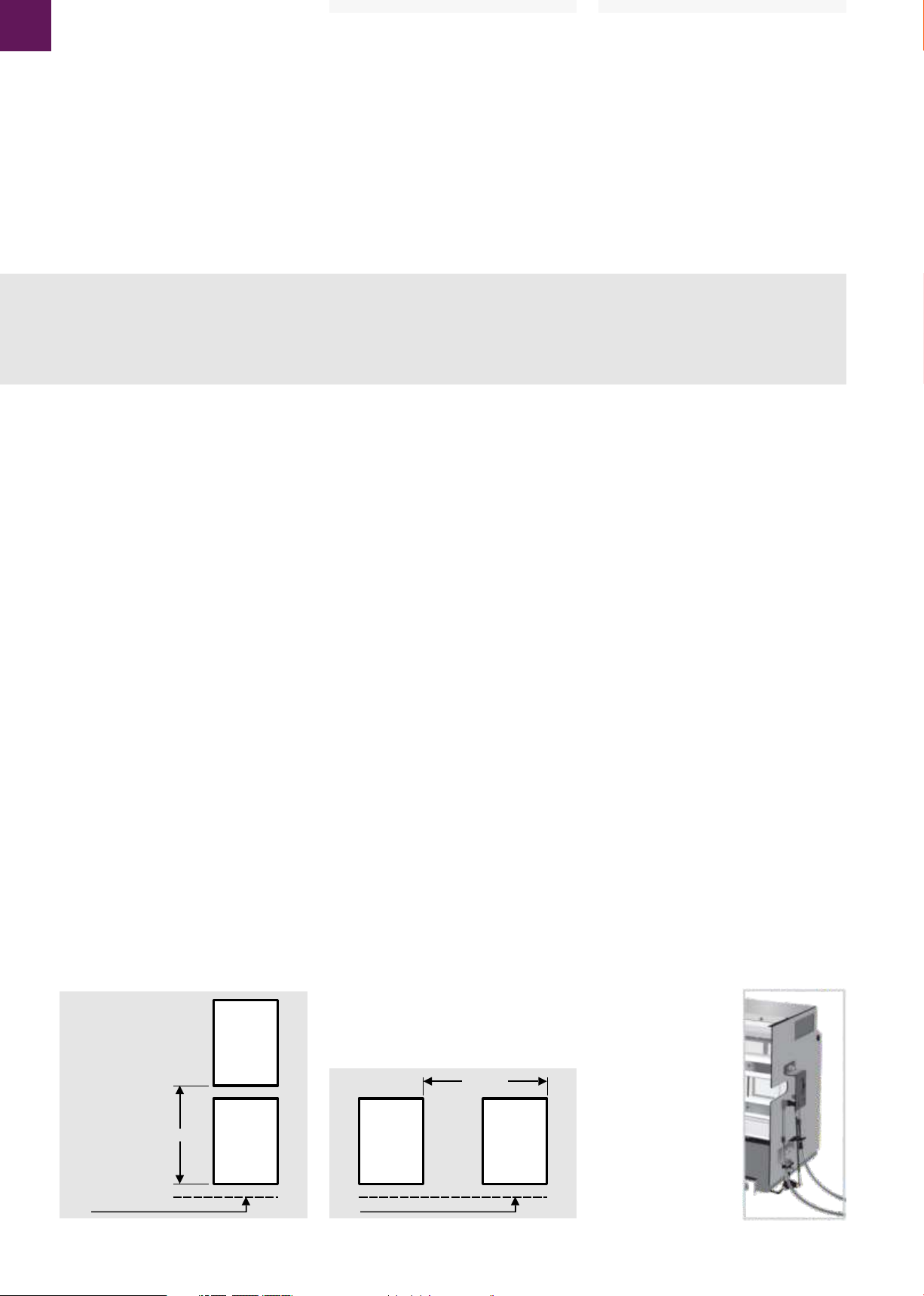
IMPORTANT CHECK
With all 3 breakers installed in Cassettes and all
parts/cables connected:
1. Close one of the breaker (for type A and B) 2 of
the breakers (for type C).
2. Then ensure there is at least 1.5 to 2.0 mm
further movement available on Drive Rod
horizontally in the direction show in right Picture
before it becomes solid in other Breakers, which are
kept trip free.
3. Adjust the link rod as described in the next page
if needed.
4. This ensures that there is no strain on linkages.
5. Repeat procedure for the other 2 Breakers.
_new image needed
For type A
A: Drive rod
A: Antriebsstange
A: Drążek napędowy
A
Wichtige Prüfung
Bei allen 3 Leistungsschalter in Einschüben und
wenn alle Teile/Bowdenzüge verbunden sind:
1. Einen der Schalter einschalten (bei Typ A und B).
Zwei Schalter bei Typ C einschalten.
2. Anschließend sicherstellen, dass mindestens 1,5
bis 2,0 mm weitere Bewegungsfreiheit am
Übertragungshebel horizontal vorhanden sind, wie
im zugehörigen Bild gezeigt, bevor sie, zum
Gewährleisten der Freiauslösung am anderen
Schalter anstoßen.
3. Justieren Sie die Verbindungsstange, wenn
nötig, wie beschrieben.
4. Dadurch wird sichergestellt, dass keine
Belastung auf der Verbindungen besteht.
5. Wiederholen Sie den Vorgang für die anderen 2
Leistungsschalter.
DEH-41 451
EntelliGuard G
WAŻNE SPRAWDZENIE
Dla wszystkich 3 wyłączników znajdujących się w
podstawach (kasetach) ze wszystkimi podłączonymi
elementami / cięgnami:
1. Zamknąć jeden z wyłączników (dla blokad typu A i
B) lub 2 wyłączniki (dla blokady typu C).
2. Dopilnować aby możliwy był dalszy ruch poziomy
drążka napędowego na długości 1.5 do 2 mm w
kierunku pokazanym na rysunku z prawej strony
zanim drążek usztywni się w pozostałych
wyłącznikach będących w stanie gotowości do
wyzwolenia.
3. W razie potrzeby wyregulować korbowód w
sposób opisany na następnej stronie.
4. Dzięki temu nie będzie naprężeń w połączeniach
cięgnowych.
5. Powtórzyć procedurę dla pozostałych 2
wyłączników.
A
For type B, C & D
Cable Interlock
13
Page 14

EntelliGuard G
Deutsch Polski
LINK ROD ADJUSTMENT NOTES
Adjustment should be required during Operational
Test Procedure to obtain correct Interlocking setting
On the ON Button:
1. Slacken locking M5 nut at the top of Ball Joint.
2. Remove M5 nut securing Ball Joint to Crank –
retain with washer for reuse.
3. For Type A unscrew Ball Joint one turn at a time
on its Link Rod to increase interlocking clearance
(Screw in to decrease clearance).
4. For Type B,C & D Screw in Ball Joint one turn at a
time on its Link Rod to increase interlocking
clearance (Unscrew to decrease clearance).
5. Re secure Ball Joint to Crank and re lock vertical
Link Rod onto Ball Joint via nut.
Justagehinweise für die
Verbindungsstangen
Die Anpassung ist während des EinsatzPrüfverfahrens erforderlich, um eine korrekte
Verriegelungs-Einstellung zur EIN-Taste zu erhalten:
1. Lösen der M5 Kontermutter an der Spitze der
Kugelverbindung.
2. Entfernen der M5 Kontermutter etc. am
Kugelgelenk und behalten Sie die Teile für die
Wiederverwendung.
3. Für Typ A Kugelgelenk eine Umdrehung
abschrauben um die Verbindungsstange zu
verlängern. (Zurückschrauben um die Strecke zu
verringern).
4. Für Typ B, C und D Kugelgelenk eine Umdrehung
einschrauben um die Verbindungsstange zu
verlängern. (Zurückschrauben um die Strecke zu
verringern).
5. Erneutes Sichern des Kugelgelenks zum Hebel
und kontern der vertikalen Verbindungsstange auf
dem Kugelgelenk über die Kontermutter.
REGULACJA KORBOWODU
Regulację należy wykonać podczas testów
działania, aby uzyskać prawidłowe ustawienie
blokujące dla przycisku ZAŁ. (ON).
1. Zluzować nakrętkę blokującą M5 na złączu
kulowym.
2. Usunąć nakrętkę M5 mocującą złącze kulowe do
wahacza – zachować z podkładką do ponownego
użycia.
3. Dla blokady typu A odkręcić złącze kulowe
każdorazowo o jeden obrót na jego korbowodzie
aby zwiększyć luz blokowania (wkręcić aby
zmniejszyć luz).
4. Dla blokad typu B, C i D wkręcić złącze kulowe
każdorazowo o jeden obrót na jego korbowodzie
aby zwiększyć luz blokowania (odkręcić aby
zmniejszyć luz).
5. Ponownie przymocować złącze kulowe do
wahacza i zablokować pionowy korbowód na
złączu kulowym używając nakrętki.
A: Link rod
B: M5 Nut
C: Ball Joint
D: M5 Nut
E: Crank
A: Verbindungsstange
B: M5 Mutter
C: Kugelgelenk
D: M5 Mutter
E: Gelenkplatte
A: Korbowód
B: Nakrętka M5
C: Złącze kulowe
D: Nakrętka M5
E: Wahacz
A
A
B
A: Link rod
B: M5 Nut
C: Ball Joint
D: M5 Nut
E: Crank
A: Verbindungsstange
B: M5 Mutter
C: Kugelgelenk
D: M5 Mutter
E: Gelenkplatte
A: Korbowód
B: Nakrętka M5
C: Złącze kulowe
D: Nakrętka M5
E: Wahacz
B
C
E
C
D
E
D
14
Page 15

English Deutsch
Cable Dimensions for all types
Dim'n 'D': max. distance for given cable size in table below from LHS of Cass. 1 to RHS of Cass. 3
Dim'n 'D': max. distance for given cable size in table below from
LHS of Cass. 1 to RHS of Cass. 2 (Ditto for 2 to 3)
Cable
Anchor
Point
12
Breaker 1 Breaker 2 Breaker 3
122
_xx min.
Note: 125 & R125 are Centr Line distances
R125
125
135
added beyond Anchor Point added beyond Anchor Point
Note: Dimension 'C' assumes a supported 'Flat run'. If not supported cable will droop, thus increasing required length.
Dim'n 'C' (max. flat run)
Dim'n 'A'
Dim'n 'B'
between Anchor Points
Calculated distance between points X & Y = 211 mm
Bowdenzugabmessungen für alle Ausführungen
Maß 'D': max. Entfernung für Bowdenzuggröße in Tabelle von LHS Schalter 1 to RHS Schalter 3
max. Entfernung für Bowdenzuggröße in Tabelle
Maß 'D':
von LHS Schalter 1 zu RHS Schalter 2 (Dito für 2 zu 3)
Bow.zug
Basispunkt
12
DEH-41 451
135
EntelliGuard G
28
Cable
Anchor
Point
114
R125
125
X
Y
28
Bow.zug
Basispunkt
Cable Interlock
122
_xx min.
Hinweis: 125 & R125 sind Mittellinien Abmessungen
R125
125
135
über dem Basispunkt hinaus über dem Basispunkt hinaus
Hinweis: Abmessung 'C' bezieht sich auf eine unterstützte Länge. Durchhänge verlängern das benötigte Maß.
Dim'n 'C' (max. Freilänge)
Dim'n 'A'
Dim'n 'B'
zwischen den Basispunkten
Wymiary cięgien dla wszystkich typów blokad
Schalter 1 Schalter 2 Schalter 3
'D'
Dim'n 'A'
Punkt
zamocowania
cięgna
122
_xx min.
12
LHS of Cass. 1 to RHS of Cass. 2 (Ditto for 2 to 3)
Podstawa 1 Podstawa 2 Podstawa 3
Note: 125 & R125 are Centr Line distances
R125
125
'D'
Dim'n 'C' (max. flat run)
Berechnete Entfernung von X & Y = 211 mm
135
Calculated distance between points X & Y = 211 mm
Y
Y
R125
125
28
R125
125
114
X
Punkt
zamocowania
cięgna
114
X
135
added beyond Anchor Point added beyond Anchor Point
Uwaga: Wymiar 'C' przy założeniu że cięgno jest prowadzone płasko, na podporach. Bez podpór cięgno będzie opadać, zwiększając długość.
między punktami zamocowania
Cable Length Table (mm) | Tabelle der Bowdenzuglängen (mm) | Tabela długości cięgien
A B C D
1000 730 72 for inboard use only | nur für Innenräume | _xxx
1600 1330 672 882 use with pairs only | nur paarweise verwenden | _xxx
2000 1730 1072 1282
2500 2230 1572 1782
3000 2730 2072 2282
4000 3730 3072 3282
Dim'n 'B'
135
15
Page 16

EntelliGuard G
These instructions do not purport to cover all details or variations
in equipment nor, to provide contingency to be met in connection
with installation, operation, or maintenance. Should further
information be desired, or should particular problems arise which
are not covered sufficiently for the purchaser's purposes, the
matter should be referred to GE.
Germany
GE Consumer & Industrial
Berliner Platz 2-6
D-24534 Neumünster
T +49 180 4 437378
F +49 4321 201 490
E service.g@ge.com
Netherlands
GE PowerControls NL
Parallelweg 10
7482 CA Haaksbergen
T +31 53 573 03 03
F +31 53 572 63 15
E service.nl@ge.com
Spain
GE Power Controls Spain
Marques de Comillas
08225 Terrassa
T +34 93 736 5742
F +34 93 789 0943
E service.e@ge.com
Diese Anweisung erhebt weder den Anspruch alle Details und
Ausstattungsmöglichkeiten zu beschreiben, noch alle
Eventualitäten, die im Zusammenhang mit der Installation, dem
Betrieb oder der Wartung erfüllt werden müssen. Sollten Sie
weitere Informationen wünschen, oder sollten besondere
Probleme auftreten, die nicht ausreichend für die Zwecke des
Betreibers beschrieben sind, so sollten Sie sich direkt an GE
wenden.
UK
GE Power Controls UK
Foundry Lane
Widnes
T +44 151 420 9 636
F +44 151 420 9 634
E service.uk@ge.com
Poland
GE Power Controls
ul. Leszczyńska 6
43-300 Bielsko-Biala
T +48 33 828 6343
F +48 33 811 8702
E service.pl@ge.com
France
GE Power Controls France
1572, route de Guise
02100 Harly (Saint-Quentin)
T +33 3 23 50 70 66/67
F +33 3 23 50 70 65
E service.f@ge.com
Niniejsza instrukcja nie obejmuje wszystkich możliwych wersji
urządzeń i szczegółów technicznych, nie uwzględnia też
wszystkich możliwych sytuacji jakie mogą mieć miejsce podczas
montażu, eksploatacji, konserwacji lub napraw. Jeśli konieczne
będą dodatkowe informacje lub wystąpią problemy nie
uwzględnione w tej instrukcji w sposób wystarczający - prosimy
o kontakt z GE.
Italy
GE Power Controls Italy
Via Monte Avaro 7
24060 Chiuduno Bergamo
T +39 35 83 63 321
F +39 35 83 63 301
E service.it@ge.com
Belgium
GE Power Controls Belgium
Nieuwe Vaart 51
9000 Gent
T +32 9 265 21 11
F +32 9 265 28 12
E service.b@ge.com
GE imagination at work
GE Consumer & Industrial GmbH
Berliner Platz 2-6
D-24534 Neumünster
Germany
Telefon ++49 4321-201-0
Fax ++49 4321-201-444
Weitere Infos über GE Consumer & Industrial:
www.ge.com/de
 Loading...