

Page 1
Introduction
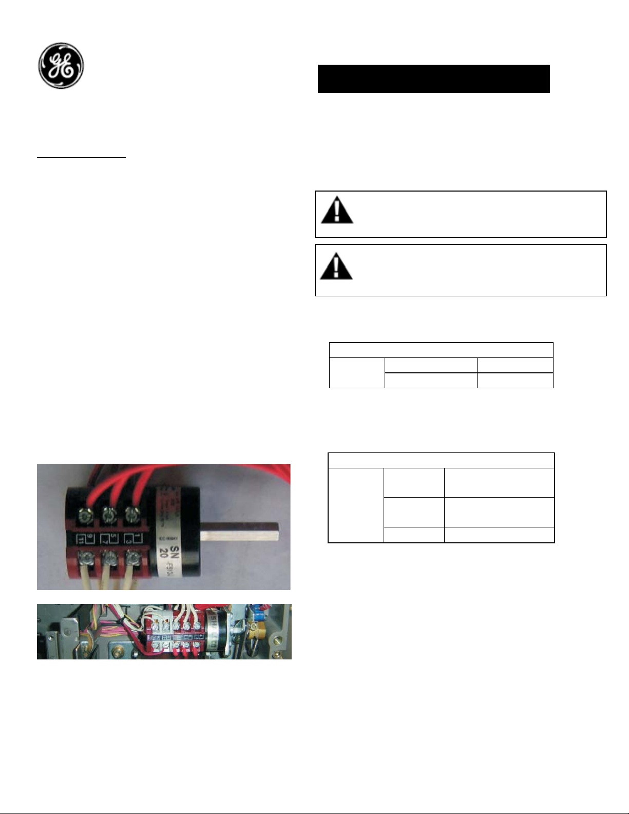
Auxiliary Switch:
Auxiliary contacts indicate the position of the
Circuit Breaker main contacts. These contacts
operate simultaneously with the breakers main
contacts. Default breaker configuration consists
of 3 normally open (NO) and 3 normally closed
(NC) contacts. The STD Auxiliary switch (GAUX3R)
can be replaced with any of the following
configurations to increase the number of
available contacts.
• Power rated contacts 8 NO & 8 NC
(GAUX6R)
• Power rated contacts 3 NO & 3 NC plus
Low Signal rated contacts 2 NO & 2 NC
(GAUX5R)
• Power rated contacts 4 NO & 4 NC plus
Low Signal rated contacts 4 NO & 4 NC
(GAUX8R)
See Wiring Diagram on last page for Power Rated
and Low Signal Connections
DEH-41415 Installation Instructions
EntelliGuard ® G Circuit Breaker
Accessories
Auxiliary Switch
WARNING: Before installing any accessories, turn the
breaker OFF, disconnect it from all voltage sources,
and discharge the closing spings.
AVERTISSEMENT: Avant d’installer tout accessoire,
mettre le disjoncteur en position OFF, le déconnecter
de toute tension d’alimentation , et décharger les
resorts d’armement
Table 1. Auxiliary switch ratings
AC Ratings
AC
220/240V 10A
110/120V 15A
DC Ratings*
5A (6 contacts in
series)
10A (3 contacts in
series)
DC
240V
125V
24V 15A
* DC ratings are not UL listed
Note:
The following Aux options are not available when
a Side Mounted Disconnect or Coil Signaling
Contacts are installed in the breaker
• Power rated contacts 4 NO & 4 NC plus
Low Signal rated contacts 4 NO & 4 NC
(GAUX8R)
Power rated contacts 8 NO & 8 NC (GAUX6R)
1
Page 2
Use the following procedure to install the
Auxiliary Switch accessory into the circuit
breaker.
1. Verify that the rating on the Auxiliary Switch
identification plate matches the voltage rating
required for the application, as listed in Table 1.
2. Side mounted Breakers are limited to maximum 5 NO & 5 NC contacts.
3. Verify Secondary Disconnect Block B is present.
4. Turn the breaker off and discharge the closing
springs by depressing the OFF and ON buttons in
the sequence OFF-ON-OFF. Verify that the
breaker OFF-ON indicator shows OFF on a green
background and that the charge indicator shows
DISCHARGE on a white background. If installing
in a draw-out type breaker remove breaker from
adaptor (cassette) before continuing.
5. Loosen the 6 screws on front cover (fascia)
using a posidrive screw driver as shown in Fig 1.B
Rotate the charging handle down and slide the
front cover over the handle to remove the front
cover as shown in Fig. 1.C.
Figure 2. Unplug the existing connectors.
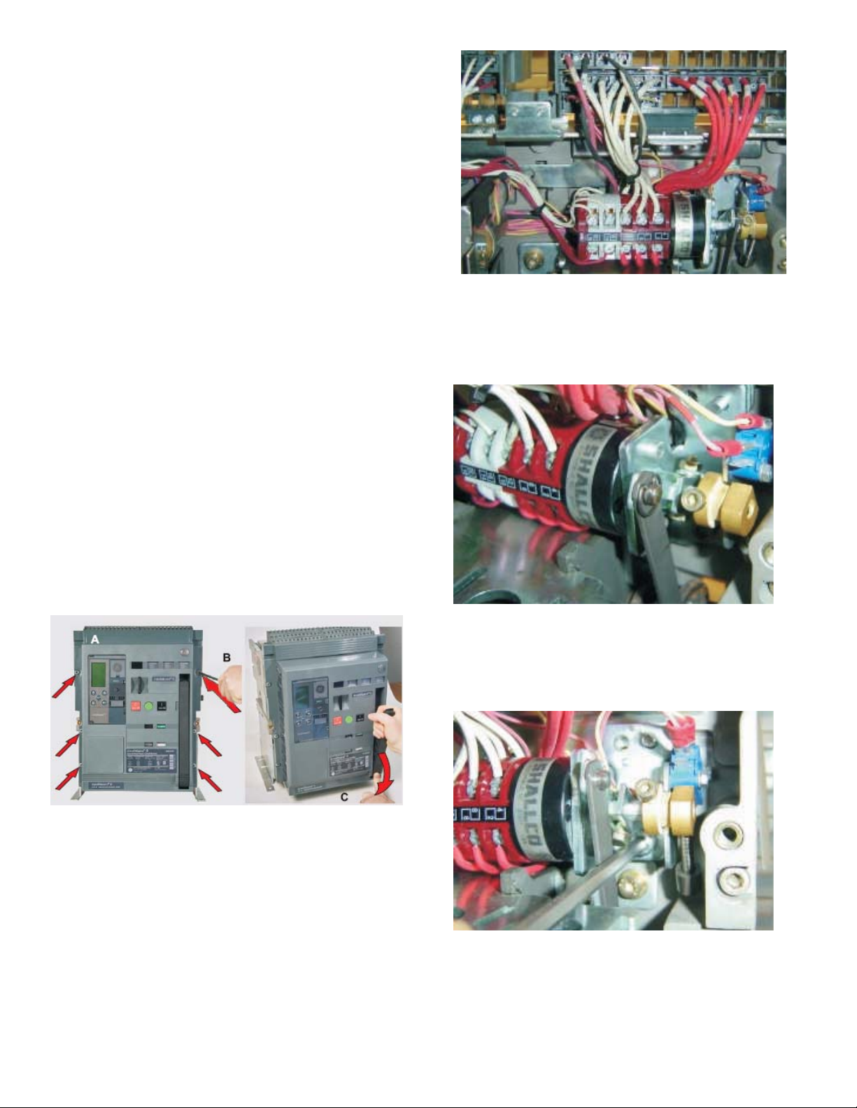
7.
Remove the e-ring from the Auxiliary switch
link to the mechanism as shown in Fig. 3.
Figure 3. E-ring removal
8. Remove the existing M5 nut & M6 screw from
the assembly as shown in Fig. 4.
Figure 1. (A) Front Cover (B) Screw Removal (C) Handle
Rotation
6. Unplug the existing Auxiliary switch connector
plugs from the secondary disconnect as shown
in Fig. 2.
Figure 4. Remove the Screw & nut
9. Remove the existing Auxiliary switch assembly
from the housing as shown in Fig. 5.
2
Page 3

13. Plug the connectors from the Auxiliary switch
into the secondary disconnect terminals marked
as A14, A15 etc (refer wiring diagram for all wiring
points) in the respective terminals as shown in
Fig. 8.
Figure 5. Remove the existing Auxiliary switch
assembly
10. Insert the new Auxiliary switch assembly
e housinth
g as shown in Fig. 6.
on
Figure 6. Assemble the Auxiliary switch
11. Assemble back the screw and nu
xplained in step 6.
e
ts as
12. Assemble the e-r
witch link and the mechanism link as shown in
s
ing between the Auxiliary
Fig. 7.
Figure 8. Connector’s assembly
9. To reinstall the cover, rotate the charging
handle down and slide the front cover over the
handle to assemble the front cover to housing as
shown in Fig. 9.
Figure 9.
10. Ensure the fascia is aligned properly with the
trip unit and the pad lock features of the breaker.
11. Fasten the 6 mounting screws of fascia with
Figure 7. E-ring assembly
the housing using a pozidrive screwdriver. Apply
torque of 6 Nm (4.42 ft-lbs).
3
Page 4

Reference:
Auxiliary Switch Connection Scheme:
GE
41 Woodford Ave, Plainville, CT 06062
www.geelectrical.com
© 2009 General Electric Company
These instructions do not purport to cover all details or variations in equipment nor, to provide contingency to be met in connection
with installation, operation, or maintenance. Should further information be desired, or should particular problems arise which are not
covered sufficiently for the purchaser’s purposes, the matter should be referred to GE.
-
4
 Loading...