

Page 1
current
Sealed
DEH41118 Installation Instructions R01
Trip Paddle
Mounting
Manual Reset Assembly
Network Interlock
15
20 16
21 19
NI Reset
NI Status
3 2
5
DEH41118 Installation Instructions R02
g
Introduction
The Network Interlock provides a means of locking out a
circuit breaker to coordinate its operation with other
circuit breakers in the distribution network. When
activated by the EntelliGuard Messenger™, the Network
Interlock prevents the circuit breaker from closing. When
the EntelliGuard Messenger issues a reset signal, the
circuit breaker can be closed either remotely or locally.
The Network Interlock accessory includes a manual reset
lever to reset the device in the absence of a signal from the
EntelliGuard Messenger.
The Network Interlock contains a microswitch to remotely
indicate the state of the lockout and thus whether or not
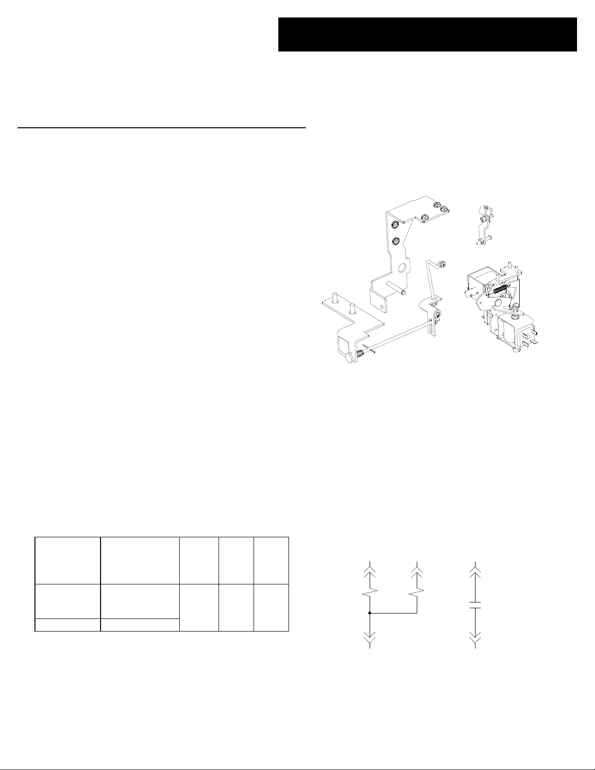
the circuit breaker can be closed. The Network Interlock
kit (EGNTWKLFKIT) consists of the Network Interlock
module (EGNTWKLFRPLC), mounting bracket, trip
paddle, manual reset assembly, and hardware, as
illustrated in Figure 1. The catalog information for large
frame Network Interlock kit and replacement module is
listed in Table 1.
Note: The Network Interlock kit is for use with
EntelliGuard circuit breakers installed in Entellisys™ Low
Voltage Switchgear only.
Note: A Bell Alarm with Lockout and Network Interlock
cannot be installed concurrently in a circuit breaker.
Description Catalog Number
Complete Kit
(NI Module+
Mounting)
NI Module EGNTWKLFRPLC
EGNTWKLFKIT
Table 1. Catalog numbers and electrical ratings
Voltage
Rating
60 Hz
VAC
120
Inrush
A
6
EntelliGuard ™ Power Circuit Breaker
Accessories
Network Interlock for 3200-5000 Ampere
Circuit Breakers
Bracket
Module
(EGNTWKLFRPLC)
4
Contact
current
A
1.43
Figure 1. Network Interlock kit assembly (EGNTWKLFKIT)
Operation
The Network Interlock consists of a set solenoid, a reset
solenoid, and a status switch. The device connections to
the secondary disconnect are shown in Figure 2. When
voltage is applied across the set solenoid, the device locks
out the circuit breaker. Conversely, when voltage is applied
to the reset solenoid or when the manual reset knob is
pulled, the Network Interlock allows the circuit breaker to
re - close.
NI Set
Figure 2. Network Interlock connections to secondary disconnect.
(Contact shown in RESET state.)
1
Coil
Coil
Page 2
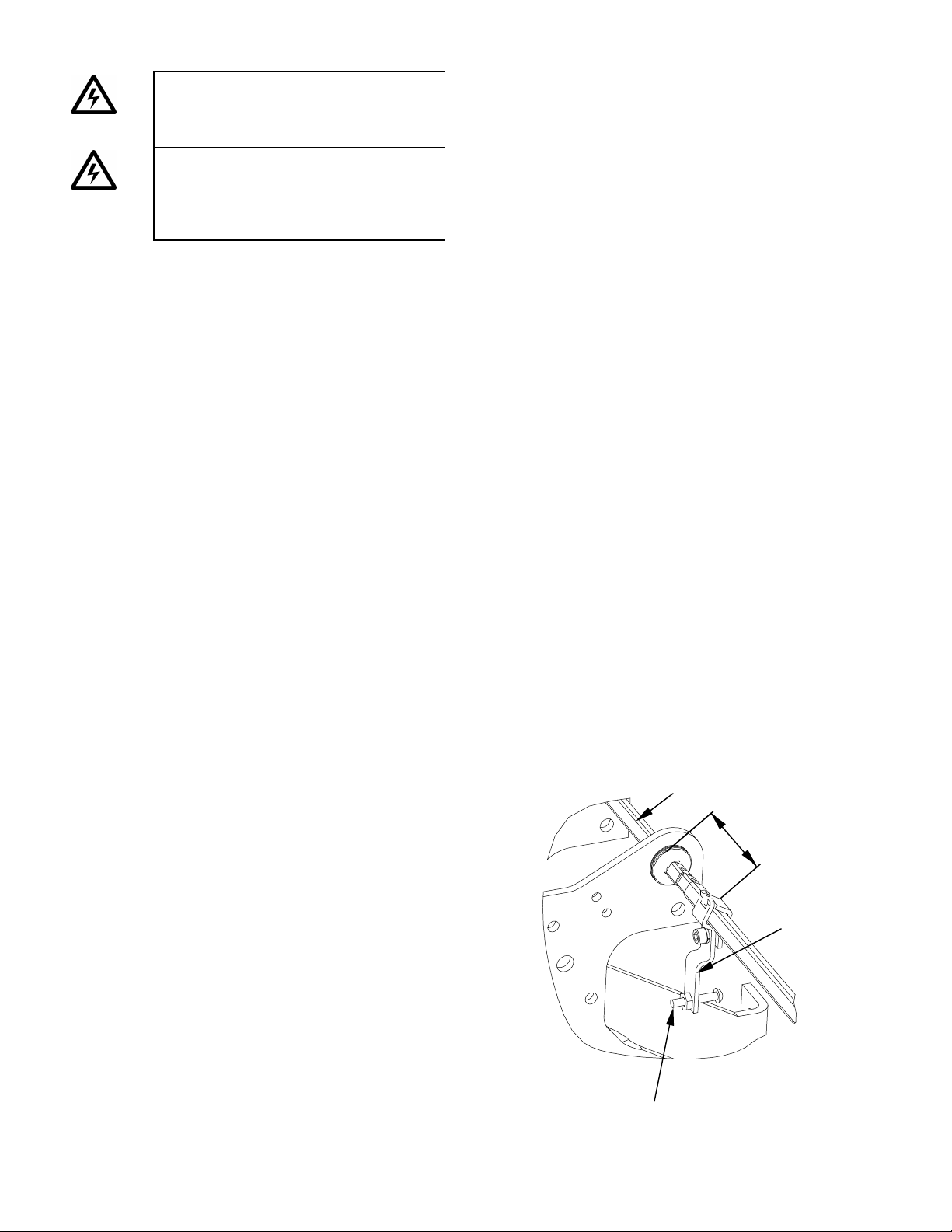
Trip Paddle
Trip Shaft
Adjusting Screw
1.62”
WARNING: Before installing any
accessories, turn the breaker OFF,
disconnect it from all voltage sources,
and discharge the closing springs.
AVERTISSEMENT: Tourner le
disjoncteur à la position OFF, le
débrancher de toute source de tension et
décharger les ressorts de fermeture avant
l’installation de tout accessoire.
Kit Installation Instructions
Use the following installation procedure for breakers
that were not equipped with a Network Interlock
accessory at the factory.
1. Open the circuit breaker and remove it from the
cubicle or substructure. Check to ensure the breaker
closing springs are DISCHARGED. (See User’s Guide
DEH202 or Maintenance Manual DEH204 for detailed
instructions.)
2. Carefully place the circuit breaker on a suitable
working surface, resting on the primary disconnects,
so that the bottom of the circuit breaker is accessible.
3. Assemble the trip paddle over the circuit breaker trip
shaft as shown in Figure 3. Secure the trip paddle to
the trip shaft using the # 10-32 screw and spring
washer provided. Install the # 8-32 adjusting screw and
nut as shown in Figure 3.
4. Assemble the Network Interlock mounting bracket to
the circuit breaker frame using two sets of 3/8-inch
countersunk bolts and washers as shown in Figure 4.
5. Fasten the Network Interlock module to the mounting
bracket using three sets of # 8-32 nuts, spring washers,
and flat washers as shown in Figure 5.
6. Ensure the Network Interlock is in the RESET state
(shown in Figure 7) by manually rotating the reset
lever counterclockwise. If the Network Interlock was
SET, this operation will cause the set lever to retract
(counterclockwise) away from the trip paddle.
7. With the breaker open, charge the breaker closing
springs. Do not close the breaker. Adjust the gap
between the set lever and the trip paddle by rotating
the adjusting screw as shown in Figure 7. The distance
between the set lever and the trip paddle must be
between 0.06 and 0.09 inch.
8. Manually push the set lever toward paddle, locking the
Network Interlock into the SET position (shown in
Figure 6). Check to ensure that this operation causes
the trip paddle to move.
9. Close the breaker by either depressing the close button
or activating the close coil circuit. The breaker should
not have closed since the Network Interlock was SET.
10. Fasten the manual reset assembly bracket to the
breaker frame using two sets of 1/4-inch hex-head
bolts and lock washers as shown in Figure 5.
11. Assemble the two reset rods as shown in Figure 5 and
Figure 6. Fasten the top end of the vertical rod to the
reset lever with two flat washers and one push nut as
shown Figure 6.
12. Pull the manual reset knob shown in Figure 5. Check
that the Network Interlock has returned to the RESET
state, as shown in Figure 7.
13. Charge and close the breaker. The breaker should
close properly since the Network Interlock is RESET.
14. Open the breaker. Connect six wires to the available
terminals on the Network Interlock device using the
crimp-on terminals provided. Connect two of the wires
to the NC and COM terminals of the microswitch as
shown in Figure 9.
15. Route the wires from the Network Interlock to the
secondary disconnect as shown in Figure 8 and secure
them with cable ties.
16. Using the spade terminals provided, connect a wire
from the trip and reset solenoids to terminals 15 and
20 of the secondary disconnect, respectively. Connect
the other two solenoid wires to terminal 21. Connect
the two microswitch wires to terminals 16 and 19.
Figure 10 shows the secondary disconnect numbering
scheme.
17. Reset the Network Interlock by pulling the manual
reset knob. The Network Interlock status circuit should
be open. Close the breaker manually or electrically.
The breaker should close properly.
18. Set the Network Interlock by applying 120 VAC across
terminals 15 and 21 on the secondary disconnect. The
breaker should trip open and the status circuit should
change from open to close.
19. Charge the breaker manually or electrically. Close the
breaker. The breaker should trip open, discharging
the closing springs.
20. Reset the Network Interlock by applying 120 VAC
across terminals 20 and 21 on the secondary
disconnect. The status circuit should change from
closed to open.
21. Charge and close the breaker. The breaker should
close properly.
22. Set the Network Interlock, and repeat Steps 17 through
21 five times.
Figure 3. Mounting the trip paddle assembly on the trip shaft
Page 3
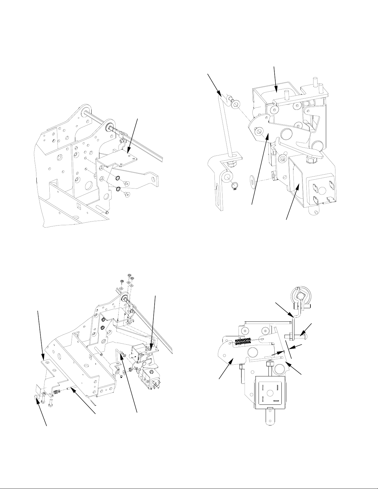
Mounting Bracket
Horizontal and Vertical Reset
Manual Reset Knob
Manual Reset
NI Module
module
Vertical Reset R
od Reset Lever
Reset Solenoid
Set Solenoid
Trip Paddle
0.06”
–
0.09”
Adjusting
Set Lever
Reset Lever
Assembly Bracket
Figure 4. Mounting bracket assembly
Figure 6. Manual reset assembly interface with Network Interlock
Screw
Figure 5. Network Interlock module and manual reset mounting
Rods
Figure 7. Trip paddle and set lever gap calibration. (Breaker
charged. NI module shown in RESET position.)
Page 4

27 26 25 24 23 22
NC
COM
NO
Figure 8. Wire routing from the Network Interlock to the secondary disconnect
Figure 9. Microswitch terminals.
9 8 7 6 5 4 3 2 1
18 17 16 15 14 13 12 11 10
21 20 19
36 35 34 33 32 31 30 29 28
Figure 10. Terminal numbering scheme of the secondary
disconnect as seen from the front of the circuit breaker.
Page 5

WARNING: Before installing any
accessories, turn the breaker OFF,
disconnect it from all voltage sources,
and discharge the closing springs.
AVERTISSEMENT: Tourner le
disjoncteur à la position OFF, le
débrancher de toute source de tension et
décharger les ressorts de fermeture avant
l’installation de tout accessoire.
Module Replacement Instructions
Removing the Network Interlock Module
Use the following procedure, illustrated in Figure 5 and
Figure 6 to remove the Network Interlock module.
1. Disconnect the six wires from the Network Interlock
module. Label each wire as it is removed. Cut wire ties
as necessary.
2. Remove the push nut and washer from the top of the
manual reset rod and slide the rod out of the reset lever
as shown in Figure 6.
3. Remove the Network Interlock module from the
mounting plate by removing the three nuts and
washers, as shown in Figure 5.
Installing the Network Interlock Module
Use the following procedure to install the Network
Interlock module as a replacement, as illustrated in
Figure 5 and Figure 6.
1. Open the circuit breaker and remove it from the
cubicle or substructure. Check to ensure the breaker
closing springs are DISCHARGED. (See DEH202 or
DEH204 for detailed instructions.)
2. Carefully place the circuit breaker on a suitable
working surface, resting on the primary disconnects, so
that the bottom of the circuit breaker is accessible.
3. Fasten the Network Interlock module to the mounting
bracket using three sets of # 8-32 nuts, spring washers,
and flat washers as shown in Figure 5.
4. Ensure the Network Interlock is in the RESET state
(shown in Figure 7) by manually rotating the reset lever
counterclockwise. If the Network Interlock was SET,
this operation will cause the set lever to retract away
from the trip paddle.
5. With the breaker open, charge the breaker closing
springs. Do not close the breaker. Adjust the gap
between the Network Interlock set lever and paddle by
rotating the adjusting screw as shown in Figure 7. The
distance between the set lever and the trip paddle must
be between 0.06 and 0.09 inch.
6. Manually push the set lever toward paddle, locking the
Network Interlock into the SET position. Check to
ensure that this operation causes the trip paddle to
move.
7. Close the breaker by either depressing the close button
or activating the close coil circuit. The breaker should
not have closed since the Network Interlock was SET.
8. Fasten the top end of the vertical manual reset rod to
the reset lever with the push nut shown in Figure 6.
9. Pull the manual reset knob. Check that the Network
Interlock has returned to the RESET state, as shown in
Figure 7.
10. Charge and close the breaker. The breaker should
close properly since the Network Interlock is RESET.
11. Open the breaker. Connect six wires to the available
terminals on the Network Interlock device. Connect
two of the wires to the NC and COM terminals of the
microswitch as shown in Figure 9.
12. Reset the Network Interlock by pulling the manual
reset knob. The Network Interlock status circuit should
be open. Close the breaker manually or electrically.
The breaker should close properly.
13. Set the Network Interlock by applying 120 VAC across
terminals 15 and 21 on the secondary disconnect. The
breaker should trip open and the status circuit should
change from open to close.
14. Charge the breaker manually or electrically. Close the
breaker. The breaker should trip open, discharging
the closing springs.
15. Reset the Network Interlock by applying 120 VAC
across terminals 20 and 21 on the secondary
disconnect. The status circuit should change from
closed to open.
16. Charge and close the breaker. The breaker should
close properly.
17. Set the Network Interlock, and repeat Steps 12
through 16.
Page 6

Page 7

Page 8

These instructions do not cover all details or variations in equipment nor do they provide for every possible contingency that
may be met in connection with installation, operation, or maintenance. Should further information be desired or should
particular problems arise that are not covered sufficiently for the purchaser’s purposes, the matter should be referred to the
GE Company.
g
GE Consumer and Industrial
General Electric Company
41 Woodford Avenue, Plainville, CT 06062
DEH41118 R02 1005 © 2005 General Electric Company
 Loading...