

Page 1

Page 2

This book replaces the Instruction Books GEI-100332A Rev. 7.5 , GEI-100332B Rev.7.6 and GEI100332G REV. 9.2.0.
The up-to-dating is referred to SW version 9.2XX
These instructions do not purport to cover all details or variations in equipment, nor to provide every
possible contingency to be met during installation, operation, and maintenance. If further information
is desired or if particular problems arise that are not covered sufciently for the purchaser’s purpose,
the matter should be referred to GE Consumer & Industrial.
This document contains proprietary information of General Electric Company, USA and is furnished to
its customer solely to assist that customer in the installation, testing, operation, and/or maintenance
of the equipment described. This document shall not be reproduced in whole or in part nor shall its
contents be disclosed to any third party without the written approval of GE Consumer & Industrial.
© 2009 by General Electric Company, USA. All rights reserved.
Page 3

DV-300 Adjustable Speed Drives
TABLE OF CONTENTS
SAFETY SYMBOL LEGEND ................................................................................................... XIV
BLOCK DIAGRAM LEGEND .................................................................................................. XIV
1 - SAFETY PRECAUTIONS - PRECAUTIONS DE SECURITÉ ............................................1
2 - DESCRIPTION, COMPONENT IDENTIFICATION AND SPECIFICATIONS ...................1
2.1 GENERAL ......................................................................................................................................... 1
Functions and features (Overview) ......................................................................................... 3
2.2 UPON DELIVERY INSPECTION PROCEDURES ................................................................................... 4
Storage, Transport .................................................................................................................. 4
2.2.1 Device setting ................................................................................................................... 4
2.3 DRIVE KEYPAD DESCRIPTION ........................................................................................................... 6
Keypad ....................................................................................................................................... 6
LEDs ........................................................................................................................................... 7
2.4 SPECIFICATIONS .............................................................................................................................. 8
2.4.1 Standards .......................................................................................................................... 8
2.4.2 AC Input ............................................................................................................................ 8
2.4.3 Output ........................................................................................................................................................................ 10
Output current ...................................................................................................................... 10
Armature circuit ................................................................................................................... 10
Field circuit ........................................................................................................................... 11
Output voltage ...................................................................................................................... 12
Armature circuit ................................................................................................................... 12
Field circuit ........................................................................................................................... 12
2.4.4 Control section ................................................................................................................ 13
2.4.5 Accuracy ......................................................................................................................... 14
2.5 DIMENSION AND WEIGHTS ........................................................................................................... 15
2.6 WATT LOSS.................................................................................................................................... 18
2.7 MOTORS, ENCODER, TACHOMETER .............................................................................................. 19
2.7.1 Motors............................................................................................................................. 19
2.7.2 Encoder / Tachometer ...................................................................................................... 20
3 - INSTALLATION GUIDELINES .......................................................................................1
3.1 PERMISSIBLE AMBIENT CONDITION ............................................................................................... 1
3.2 DISPOSAL OF THE DEVICE ............................................................................................................... 2
3.3 INSTALLATION, MOUNTING CLEARANCE ........................................................................................ 2
Mounting the device ............................................................................................................... 2
4 - WIRING PROCEDURES ...............................................................................................1
4.1 REMOVING THE FRONT COVER ....................................................................................................... 1
—————— TABLE OF CONTENTS ——————
I
Page 4

GEI-100332Ga
Terminal Assignments/Cable Sections .................................................................................... 1
4.2 WIRING THE DRIVE .......................................................................................................................... 1
4.3 POWER SECTION ............................................................................................................................. 2
4.4 REGULATION SECTION .................................................................................................................... 6
4.4.1 R-TPD32-GE Regulation Card ............................................................................................. 6
4.5 SERIAL INTERFACE ........................................................................................................................ 12
4.5.1 Description ...................................................................................................................... 12
4.5.2 RS485 serial interface connector description ................................................................. 13
4.6 INPUT/OUTPUT EXPANSION CARD 6KCV300TBO .......................................................................... 13
4.6.1 Assignment of the plug-in terminal strip (terminals 1...15) for Option Card 6KCV300TBO ......14
4.6.2 Fitting the option card ..................................................................................................... 15
4.7 DIGITAL ENCODER INTERFACE 6KDV300DES ................................................................................. 16
4.7.1 Description ...................................................................................................................... 16
4.7.2 Terminal Assignment ....................................................................................................... 17
4.8 STANDARD CONNECTION DIAGRAMS .......................................................................................... 18
4.9 CIRCUIT PROTECTION .................................................................................................................... 23
4.9.1 Fuses ............................................................................................................................... 23
4.9.2 Fuses selection when the Overload function is activated ................................................ 26
4.9.3 Internal Fuses .................................................................................................................. 27
4.9.4 AC input contactors ......................................................................................................... 28
4.9.5 Control power protection ................................................................................................. 28
4.10 REACTORS / FILTERS ................................................................................................................... 29
4.10.1 AC input choke .............................................................................................................. 29
4.10.2 Interference suppression filters ..................................................................................... 30
4.11 ENGINEERING NOTES .................................................................................................................. 31
Potentials of the regulator section ........................................................................................ 31
External devices ................................................................................................................... 32
Connection cables ................................................................................................................ 32
5 - CONVERTER OPERATION ............................................................................................ 1
5.1 KEYPAD ............................................................................................................................................ 1
5.1.1 LEDs ................................................................................................................................. 1
5.1.2 Moving inside a menu ....................................................................................................... 2
5.1.3 Displaying parameters ....................................................................................................... 2
5.1.4. Changing / Saving parameters / Password ....................................................................... 3
Changing numerical values and text ....................................................................................... 3
Selection from predefined values............................................................................................ 4
Autotuning of Analog input ..................................................................................................... 4
Parameters Saving ................................................................................................................. 5
Entering a password ............................................................................................................... 5
II
—————— TABLE OF CONTENTS ——————
Page 5

DV-300 Adjustable Speed Drives
General unlocking of the password ......................................................................................... 6
5.1.5 Operating the drive via the Keypad .................................................................................... 6
5.1.5.1 Starting and stopping the drive ................................................................................... 7
Enabling the converter ............................................................................................................ 7
Disabling the converter ........................................................................................................... 7
Start / Stop ............................................................................................................................. 7
5.1.5.2 Failure register / Acknowledging alarms ..................................................................... 8
Clearing the failure register ..................................................................................................... 8
Acknowledging a failure alarm ............................................................................................... 9
Acknowledging when several failure alarms occur at the same time ..................................... 9
5.1.5.3 Motor potentiometer function ..................................................................................... 9
Acceleration, Deceleration ...................................................................................................... 9
Changing rotation direction................................................................................................... 10
Resetting the speed reference value ..................................................................................... 10
5.1.5.4. Jog function ............................................................................................................ 10
5.2. MENU STRUCTURE ....................................................................................................................... 11
5.3 COMMISSIONING .......................................................................................................................... 35
5.3.1 Setting jumpers and switch ............................................................................................. 35
5.3.2 Checking the wiring and the auxiliary voltages ............................................................... 36
5.3.3 Basic settings of the converter ........................................................................................ 36
5.3.4 START UP procedures ..................................................................................................... 37
Motor data ........................................................................................................................... 37
Limits .................................................................................................................................. 38
Speed feedback setting ........................................................................................................ 38
Alarms .................................................................................................................................. 38
Overload control .................................................................................................................. 38
Analog inputs 1, 2 and 3 ...................................................................................................... 38
5.3.5 Drive tuning ..................................................................................................................... 39
5.3.5.1 Self tuning of the current regulator .......................................................................... 39
5.3.5.1.1 Checking current regulator performance using parameter Eint .............................. 40
5.3.5.2 Self tuning of the speed regulator ............................................................................ 40
5.3.5.3 Field converter .......................................................................................................... 42
Selection of the functioning system ..................................................................................... 42
Setting the rated field current ............................................................................................... 42
Flux current min/max............................................................................................................ 43
5.3.6 Manual tuning of the regulators ....................................................................................... 43
Using the Test generator ....................................................................................................... 43
Manual tuning of speed regulator ......................................................................................... 44
Manual tuning of field current regulator ................................................................................ 45
Voltage regulator in the field converter ................................................................................. 47
5.3.7 Others tuning .................................................................................................................. 49
—————— TABLE OF CONTENTS ——————
III
Page 6

GEI-100332Ga
Flux / if curve tuning (Flux / if curve) .................................................................................... 49
Speed-up function ................................................................................................................ 51
Setting of the speed zero logic ............................................................................................. 51
Adaptive of the speed regulator ............................................................................................ 52
6 - FUNCTION DESCRIPTION ........................................................................................... 1
Functions and parameters ...................................................................................................... 1
Explanation of parameter tables ............................................................................................. 2
6.1 ENABLES.......................................................................................................................................... 3
6.1.1 Enable drive ....................................................................................................................... 4
6.1.2 Start / Stop ........................................................................................................................ 5
6.1.3 Fast stop ........................................................................................................................... 6
6.1.4 Quick Stop ......................................................................................................................... 7
6.1.5 External fault ..................................................................................................................... 7
6.2 BASIC START UP MENUS ................................................................................................................ 8
DRIVE STATUS ........................................................................................................................ 8
START UP ............................................................................................................................... 8
First basic setting ................................................................................................................... 8
Motor data .............................................................................................................................. 8
Limits ..................................................................................................................................... 9
Speed feedback ...................................................................................................................... 9
Alarms .................................................................................................................................... 9
Overload control ..................................................................................................................... 9
Analog inputs ....................................................................................................................... 10
Self tuning of current regulator ............................................................................................. 10
Self tuning of speed regulator ............................................................................................... 10
Final operation ...................................................................................................................... 11
TUNING ................................................................................................................................ 11
Current self tuning ................................................................................................................ 11
Speed self tune ..................................................................................................................... 11
Manual tuning of speed regulator, field regulator and voltage regulator ................................ 11
IV
6.3 MONITOR ....................................................................................................................................... 12
6.4 INPUT VARIABLES ......................................................................................................................... 16
6.4.1 Ramp ref .......................................................................................................................... 17
6.4.2 Speed ref ......................................................................................................................... 18
6.4.3 Torque current reference (T current ref) ........................................................................... 20
6.5 LIMITS ............................................................................................................................................ 21
6.5.1 Speed Limits.................................................................................................................... 21
6.5.2. Armature current limits (Current limits) .......................................................................... 23
6.5.3 Flux limits ........................................................................................................................ 25
6.6 RAMP ............................................................................................................................................. 26
6.6.1 Acceleration, Deceleration, Quick Stop ........................................................................... 27
—————— TABLE OF CONTENTS ——————
Page 7

DV-300 Adjustable Speed Drives
6.6.2 Ramp shape and control commands ...............................................................................28
6.7 SPEED REGULATION (SPEED REGULAT) ......................................................................................... 31
6.7.1 Speed regulator ............................................................................................................... 32
6.7.1.1 Self tuning of Speed regulator ................................................................................. 33
6.7.2 Spd zero logic .................................................................................................................. 34
6.7.3 Speed up ......................................................................................................................... 35
6.7.4. Droop function ................................................................................................................ 36
6.7.5 Inertia/Loss compensation .............................................................................................. 38
6.8 CURRENT REGULATION (CURRENT REGULAT) .............................................................................. 39
6.9 FLUX REGULATION ......................................................................................................................... 41
6.10 REG PARAMETERS ....................................................................................................................... 44
6.11 CONFIGURATION .......................................................................................................................... 46
6.11.1 Operating mode selection .............................................................................................. 46
6.11.2 Speed base value, Full load current ............................................................................... 48
6.11.3 Configuration of the OK relay (Terminals 35,36) ............................................................. 48
6.11.4. Configuration of the speed feedback circuit ................................................................. 49
Ind store ctrl parameter [92] ................................................................................................. 52
Index storing parameter [13] ................................................................................................ 53
6.11.5 “Standard / American” selection, Software Version ...................................................... 53
6.11.6. Dimension factor, Face value fator ............................................................................... 54
6.11.7. Programmable alarms................................................................................................... 56
6.11.8 Address for bus operation ............................................................................................. 62
6.11.9 Password ...................................................................................................................... 63
6.12 I/O CONFIG ................................................................................................................................... 64
6.12.1 Analog Ouputs ............................................................................................................... 65
6.12.2 Analog Inputs ................................................................................................................ 67
6.12.3 Digital Outputs ............................................................................................................... 73
6.12.4 Digital Inputs ................................................................................................................. 76
6.12.5 Speed reference from encoder input (Tach follower function) ....................................... 79
6.13 ADDITIONAL SPEED FUNCTIONS (ADD SPEED FUNCT) ............................................................... 81
6.13.1 Auto capture ................................................................................................................. 81
6.13.2 Adptive spd reg ............................................................................................................. 81
6.13.3 Speed control ................................................................................................................ 84
6.13.4 Speed zero ..................................................................................................................... 86
6.14 FUNCTIONS .................................................................................................................................. 87
6.14.1 Motorpotentiometer ...................................................................................................... 87
6.14.2 Jog function .................................................................................................................. 89
6.14.3 Multi speed function ...................................................................................................... 91
—————— TABLE OF CONTENTS ——————
V
Page 8

GEI-100332Ga
6.14.4 Multi ramp function ....................................................................................................... 94
6.14.5 Speed Draw function ..................................................................................................... 98
6.14.6 Overload control .......................................................................................................... 100
6.14.7 Stop control ................................................................................................................. 121
6.14.8 Brake control ............................................................................................................... 123
6.14.9 Current limitation according to the speed (I/n curve) ................................................... 126
6.15 SPEC FUNCTIONS ...................................................................................................................... 127
6.15.1 Test generator ............................................................................................................. 127
6.15.2 Saving parameters, loading default factory settings, life time ..................................... 128
6.15.3 Failure Register ............................................................................................................ 129
6.15.4. Signal adaptation ........................................................................................................ 130
6.15.5 Pads ............................................................................................................................ 132
6.16 OPTIONS .................................................................................................................................... 135
6.16.1 Option 1 ....................................................................................................................... 135
6.16.2 Option 2 ....................................................................................................................... 135
6.16.3 PID Functon ................................................................................................................. 137
6.16.3.1 General ................................................................................................................. 138
6.16.3.2 Inputs / Outputs .................................................................................................... 138
6.16.3.3 Feed - Forward ..................................................................................................... 139
6.16.3.4 PID function ......................................................................................................... 141
6.16.3.5 Proportional - integral block .................................................................................. 143
6.16.3.6 Proportional - Derivative control block .................................................................. 147
6.16.3.7 Output reference ................................................................................................... 149
6.16.3.8 Function of calculation for Initial diameter ........................................................... 151
6.16.3.9 Procedure of calculation for initial diameter .......................................................... 153
6.16.3.10 Examples of application ...................................................................................... 154
6.16.3.11 Generic PID ......................................................................................................... 171
6.16.3.12 Application note ................................................................................................ 173
6.17 TORQUE WINDER FUNCTION ..................................................................................................... 176
6.17.1 Diameter calculation .................................................................................................... 177
6.17.2 Torque calculation ....................................................................................................... 181
6.17.2.1 Compensations and closing of the tension loop .................................................... 182
6.17.2.2 Taper function ....................................................................................................... 185
VI
6.17.3 Calculation of the speed reference .............................................................................. 186
6.17.4 Typical connection diagrams ....................................................................................... 191
6.17.5 Control logic ................................................................................................................ 195
Diameter initialization ......................................................................................................... 195
Initial phase ........................................................................................................................ 195
Automatic switching .......................................................................................................... 196
Reel stop ............................................................................................................................ 196
—————— TABLE OF CONTENTS ——————
Page 9

DV-300 Adjustable Speed Drives
Jog function ....................................................................................................................... 197
6.17.6 Application example .................................................................................................... 198
Provisions ........................................................................................................................... 208
1. Drive used as a winder – winding side = up .................................................................. 208
2. Drive used as a winder – winding side = down ............................................................. 209
3. Drive used as an unwinder – unwinding side = up ........................................................ 209
4. Drive used as an unwinder – unwinding side = down ................................................... 210
6.17.7 Block diagram ............................................................................................................. 211
6.18 DRIVECOM ................................................................................................................................. 215
6.18.1 Control word, status word, malfunction code .............................................................. 215
6.18.2 Speed .......................................................................................................................... 216
6.18.3 Speed limitation .......................................................................................................... 217
6.18.4 Acceleration / Deceleration .........................................................................................218
6.18.5 Factor function ............................................................................................................ 219
6.19 SERVICE ..................................................................................................................................... 220
7- MAINTENANCE ............................................................................................................ 1
7.1 CARE ................................................................................................................................................ 1
7.2 SERVICE ........................................................................................................................................... 1
7.3 REPAIRS ........................................................................................................................................... 1
7.4 CUSTOMER SERVICE ....................................................................................................................... 1
8 - TROUBLESHOOTING ................................................................................................... 1
Failure alarms in the keypad display ...................................................................................... 1
Other faults ............................................................................................................................. 5
9 - BLOCK DIAGRAM ........................................................................................................1
9.1 CONTROL BLOCK DIAGRAMS .......................................................................................................... 1
DV-300 Converter Overview ................................................................................................... 1
Digital Inputs /Outputs & Mapping Standard and TBO cards .................................................. 2
Analog Inputs/Outputs & Mapping.......................................................................................... 3
Speed Reference Generation .................................................................................................. 4
Ramp reference Block ............................................................................................................ 5
Speed / Current Regulator Overview ....................................................................................... 6
Speed Feedback setting ......................................................................................................... 7
Speed regulator ...................................................................................................................... 8
Speed regulator PI part ........................................................................................................... 9
Speed adaptive and Speed zero logic ................................................................................... 10
Current regulator .................................................................................................................. 11
Field current regulator .......................................................................................................... 12
Motor parameters ................................................................................................................. 13
Start and Stop management ................................................................................................. 14
Droop compensation ............................................................................................................ 15
—————— TABLE OF CONTENTS ——————
VII
Page 10

GEI-100332Ga
Inertia / Loss compensation.................................................................................................. 16
Speed Threshold / Speed control .......................................................................................... 17
PID function .......................................................................................................................... 18
Functions .............................................................................................................................. 19
LINKS Function ..................................................................................................................... 20
PAD parameters .................................................................................................................... 21
Taper Current Limits ............................................................................................................. 22
Dimension factor - Face value factor .................................................................................... 23
Test Generator ...................................................................................................................... 24
JOG function ......................................................................................................................... 25
Multispeed ........................................................................................................................... 26
Motor potentiometer ............................................................................................................ 27
Alarm mapping ..................................................................................................................... 28
9.2 POWER CIRCUIT BLOCK DIAGRAMS .............................................................................................29
9.3 REGULATION CARD ........................................................................................................................ 35
10 - PARAMETER LISTS ...................................................................................................1
10.1 COMPLETE MAIN MENU LIST ........................................................................................................ 1
10.2 NUMERICAL LIST ......................................................................................................................... 37
10.3 PARAMETERS IN ALPHABETICAL ORDER .................................................................................... 63
10.4 LIST OF HIGH PRIORITY PARAMETERS ........................................................................................ 81
11 - REPLACEMENT PARTS ............................................................................................. 1
11.1 HARDWARE CONFIGURATION (CARDS / DIP SWITCHES / JUMPERS) .......................................... 1
11.2. R-TPD32-GE REGULATION CARD .................................................................................................. 2
11.3 FIR1-... POWER/DRIVER CARDS.................................................................................................... 3
11.4 FIR2-... POWER/DRIVER CARD ...................................................................................................... 4
11.6 PBB POWER CONNECTION CARD ................................................................................................. 6
11.7 PFC1-32 FIELD CONVERTER .......................................................................................................... 6
11.8 PFC2-31 FIELD CONVERTER .......................................................................................................... 7
11.9 SN-FC FIELD SNUBBER ................................................................................................................. 7
11.10 SN4-31, SN5-31 SNUBBER .......................................................................................................... 8
11.11 SW1-31 POWER SUPPLY CARD ................................................................................................... 8
11.12 SW2-32 POWER SUPPLY CARD .................................................................................................. 9
11.13 FL-31 FILTER................................................................................................................................. 9
VIII
11.14 CN3 CONNECTION CARD ........................................................................................................... 10
11.15 I/O OPTION CARD 6KCV300TBO ................................................................................................. 10
—————— TABLE OF CONTENTS ——————
Page 11

DV-300 Adjustable Speed Drives
LIST OF FIGURES
1 - SAFETY PRECAUTIONS - PRECAUTIONS DE SECURITÉ ............................................ 1
2 - DESCRIPTION, COMPONENT IDENTIFICATION AND SPECIFICATIONS ...................1
Fig 2.1: Base diagram of a converter ......................................................................................................................................... 1
Fig. 2.5.1: Drive dimensions for 20 A ... 185 A sizes (form 1) .................................................................................................15
Fig. 2.5.2: Drive dimensions for 280 A ... 650 A sizes (form 2) ...............................................................................................16
Fig. 2.5.3: Drive dimensions for 770 A ... 1050 A sizes (form 3) .............................................................................................17
3 - INSTALLATION GUIDELINES .......................................................................................1
Figure 3.3.1: max Angle of Inclination .......................................................................................................................................2
Figure 3.3.2: Mounting Clearance ............................................................................................................................................3
4 - WIRING PROCEDURES ...............................................................................................1
Figure 4.1.1: Removing the Front Panel ....................................................................................................................................1
Figure 4.4.1: R-TPD32-GE regulation card ................................................................................................................................6
Figure 4.4.2: Disposition of terminals from 1 to 42 ....................................................................................................................9
Figure 4.5.1.1: RS485 serial interface ..................................................................................................................................... 12
Figure 4.6.2.1: Installing the option card ................................................................................................................................. 15
Figure 4.7.1.1: 6KDV300DES card .......................................................................................................................................... 16
Figure 4.8.1:Control sequencing .............................................................................................................................................. 18
Figure 4.8.2: Example for relay interface ................................................................................................................................19
Figure 4.8.3: Typical connections ...........................................................................................................................................20
Figure 4.8.4: Encoder and Tachometer Connections ...............................................................................................................21
Figure 4.8.5: Programmable Inputs/outputs (option 6KCV300TBO) with relay and contacts ................................................... 21
Figure 4.8.6: Programmable Inputs/outputs with PLC ..............................................................................................................22
Figure 4.8.7: 6KCV300DES connection .................................................................................................................................... 22
Figure 4.9.1.1: Position of the super fast fuses .......................................................................................................................23
Figure 4.11.1: Potentials of the regulator section ...................................................................................................................31
5 - CONVERTER OPERATION ............................................................................................ 1
Figure 5.1.2.1: Moving inside a menu ...................................................................................................................................... 2
Figure 5.3.6.1: Above: Actual spd; Below: Motor current. Speed P too low. ..........................................................................45
Figure 5.3.6.3: Above: Actual spd; Below: Motor current. Speed I too high. ..........................................................................45
Figure 5.3.6.2: Above: Actual spd; Below: Motor current. Speed P too high. .......................................................................... 45
Figure 5.3.6.4: Above: Actual spd; Below: Motor current. Speed P and Speed I set correctly. ............................................... 45
Figure 5.3.6.5: Above: Flux reference; Below: Flux current. The regulator behavior is not good. Jumps are due to field chan-
ging. ..................................................................................................................................................................................46
Figure 5.3.6.7: Above: Flux reference; Below: Flux current. The increment in the field current has no jump. Variation compa-
red to Fig. 4.5.7: Increase of Flux P from 2 to 10%. Flux I = 5%. ......................................................................................46
Figure 5.3.6.6: Above: Flux reference; Below: Flux current. The reduction of the field current depends on the field time con-
stant. The reg has no influence. ........................................................................................................................................46
Figure 5.3.6.8: Above: Flux; Below: Output voltage. After a speed change the field current (Flux) has some jumps. Voltage P
= 10%, Voltage I = 80%. ................................................................................................................................................. 48
Figure 5.3.6.10: Above: Flux; Below: Output voltage. After a short transient, the field current and armature voltage are con-
stant. Voltage P = 40%, Voltage I = 50%. ........................................................................................................................ 48
Figure 5.3.6.9: Above: Flux; Below: Output voltage. The gain is too low. The armature voltage increases. Voltage P = 3%,
Voltage I = 5%. ................................................................................................................................................................. 48
Figure 5.3.7.1: Curve convertion flux/current .........................................................................................................................49
Figure 5.3.7.2: Blocks diagrams of field current regulator ......................................................................................................50
Figure 5.3.7.3: Above: Actual spd; Below: Motor current jumps with the speed changes due to a high moment of inertia. The
function Speed-up is not active. ........................................................................................................................................51
Figure 5.3.7.4: Above: Actual spd; Below: Motor current. The same drive with Speed -up function active. ............................ 51
6 - FUNCTION DESCRIPTION ........................................................................................... 1
—————— TABLE OF CONTENTS ——————
IX
Page 12

GEI-100332Ga
Figure 6.1.1 Enables via potential free contacts and PLC .........................................................................................................3
Figure 6.4.1.1: Ramp references ............................................................................................................................................. 17
Figure 6.4.2.1: Speed reference ..............................................................................................................................................19
Figure 6.4.3.1: Torque current reference .................................................................................................................................20
Figure 6.6.1 : Ramp circuit ......................................................................................................................................................26
Figure 6.6.1.1: Accel, decel and Quick stop ............................................................................................................................27
Figure 6.6.2.1: Ramp shape ....................................................................................................................................................29
Figure 6.6.2.2: Ramp delay .....................................................................................................................................................29
Figure 6.6.2.3: Ramp control ................................................................................................................................................... 30
Figure 6.7.1: Speed regulation ................................................................................................................................................31
Figure 6.7.2.1: Speed zero logic ..............................................................................................................................................34
Figure 6.7.4.1: Droop compensation ........................................................................................................................................ 36
Figure 6.7.4.2: Droop function example ................................................................................................................................... 37
Figure 6.7.5.1: Inertia/Loss compensation .............................................................................................................................. 38
Figure 6.8.1: Torque current regulaton ....................................................................................................................................39
Figure 6.9.1: Motor control .....................................................................................................................................................41
Figure 6.11.4.1: Speed feedback .............................................................................................................................................50
Figure 6.11.4.2: Allowed area for Encoder 2 pulses and Motor max speed ............................................................................. 51
Figure 6.11.6.1: Calculation using dimension and face value factors.......................................................................................55
Figure 6.11.7.1: Drive enabling sequence: Main command = Terminals .............................................................................61
Figure 6.11.7.2 Drive enabling sequence: Main command = Digital ..................................................................................61
Figure 6.12.1: Arrangement of the programmable I/O ............................................................................................................64
Figure 6.12.1.1: Option card, analog output blocks .................................................................................................................66
Figure 6.12.2.1: Analog input .................................................................................................................................................. 71
Figure 6.12.2.2: Analog Input 1 window comparator ..............................................................................................................72
Figure 6.12.3.1: Digital outputs ...............................................................................................................................................74
Figure 6.12.4.1: Digital inputs .................................................................................................................................................76
Figure 6.12.5.1: Tach follower .................................................................................................................................................79
Figure 6.12.5.2: Example of application of the encoder reference ..........................................................................................80
Figure 6.13.2.1: Adaptive of the speed regulator.....................................................................................................................83
Figure 6.13.3.1: “Speed threshold” (up) and “Set speed” (down) messages .........................................................................85
Figure 6.13.4.1: Speed zero ....................................................................................................................................................86
Figure 6.14.1.1: Motor potentiometer .....................................................................................................................................88
Figure 6.14.2.1: Example of external activation in Jog mode ................................................................................................... 90
Figure 6.14.3.1: Selection of different references via terminals ...............................................................................................91
Figure 6.14.3.2: Multi speed function ......................................................................................................................................93
Figure 6.14.4.1: Multi ramp selection via terminals .................................................................................................................97
Figure 6.14.4.2: Multi ramp selection via signals .................................................................................................................... 97
Figure 6.14.5.1: Speed draw block diagram ...........................................................................................................................98
Figure 6.14.5.2: Rubber calender example ..............................................................................................................................99
Figure 6.14.6.1: Overload control (Overload mode = curr limited) ........................................................................................ 103
Figure 6.14.6.2: Overload control (Overload mode= curr not limited) ..................................................................................103
Figure 6.14.6.3: Example- Operating point of drive ................................................................................................................ 120
Figure 6.14.7.1: Start and stop management.........................................................................................................................121
Figure 6.14.8.1: Diagram of control .......................................................................................................................................124
Figure 6.14.8.2: Brake control diagram .................................................................................................................................125
Figure 6.14.8.1 Current limitation according to the speed ..................................................................................................... 126
Figure 6.15.1.1: Test generator output ..................................................................................................................................127
Figure 6.15.4.1: Structure of the signal adaptation ................................................................................................................131
Figure 6.15.5.1: Bus pads .....................................................................................................................................................134
Figure 6.16.3.1: Feed-forward block description ................................................................................................................... 139
Figure 6.16.3.2: PID blocks description .................................................................................................................................141
Figure 6.16.3.3: PI block description .....................................................................................................................................143
Figure 6.16.3.4: PD block description ................................................................................................................................... 147
Figure 6.16.3.5: Output reference block description ..............................................................................................................149
Figure 6.16.3.6: Diameter calculation block description .......................................................................................................151
Figure 6.16.3.7: Diameter calculation .................................................................................................................................... 152
X
—————— TABLE OF CONTENTS ——————
Page 13

DV-300 Adjustable Speed Drives
Figure 6.16.3.8: Nip-roll control with dancer .........................................................................................................................154
Figure 6.16.3.9: Nip-rolls control with load cell .....................................................................................................................157
Figure 6.16.3.10: Winder/Unwinder control with dancer ....................................................................................................... 161
Figure 6.16.3.11: Diameter calculation .................................................................................................................................. 165
Figure 6.16.3.12: Winder/unwinder control with sensor diameter ......................................................................................... 166
Figure 6.16.3.13: Relation between transducer signal and coil signal ...................................................................................166
Figure 6.16.3.14: Pressure control for pumps and extruder .................................................................................................. 168
Figure 6.16.3.15: Example with small and large diameter .....................................................................................................173
Figure 6.16.3.16: Relation between PI I gain PID and PI I output PID....................................................................................174
Figure 6.16.3.17: General description of the PID blocks ........................................................................................................ 175
Figure 6.17.1: Acceleration and deceleration indication ....................................................................................................... 183
Figure 6.17.2: Relation among the Taper function parameters .............................................................................................. 185
Figure 6.17.3: Operative sequence of the functioning status .................................................................................................188
Figure 6.17.4: Functioning with Jog TW enable .................................................................................................................... 190
Figure 6.17.5: Winder with an automatic switch and a closed loop tension regulation .........................................................191
Figure 6.17.6: Winder with an automatic switch and a closed loop tension regulation .........................................................192
Figure 6.17.7: Winder with an automatic switch and a closed loop tension regulation .........................................................193
Figure 6.17.8: Winder with an automatic switch and a closed loop tension regulation .........................................................194
Figure 6.17.9: Initial phase with a stopped line .....................................................................................................................195
Figure 6.17.10: Automatic switching between two coils during a winding/unwinding period ................................................ 196
Figure 6.17.11: Coil stop after the automatic switching ......................................................................................................... 197
Figure 6.17.12: Jog function to prepare the machine ............................................................................................................197
Figure 6.17.13: Drive used as a winder – winding side = up ...............................................................................................208
Figure 6.17.14: Drive used as a winder – winding side = down ........................................................................................... 209
Figure 6.17.15: Drive used as an unwinder – unwinding side = up ...................................................................................... 209
Figure 6.17.16: Drive used as an unwinder – unwinding side = down .................................................................................210
Figure 6.17.4.1: Acceleration and deceleration .....................................................................................................................219
7- MAINTENANCE ............................................................................................................ 1
8 - TROUBLESHOOTING ................................................................................................... 1
9 - BLOCK DIAGRAM ........................................................................................................1
Figure 9.2.1: Circuit block diagram: 6KDV3017Q4F ... to 6KDV3148Q4F - 6KDV3020Q4E ... to 6KDV3185Q4E .................... 29
Figure 9.2.2: Circuit block diagram: 6KDV3224Q4F ... to 6KDV3450Q4F - 6KDV3280Q4E ... to 6KDV3650Q4E .................... 30
Figure 9.2.3: Circuit block diagram: 6KDV3560Q4F ... to 6KDV3850Q4F - 6KDV3770Q4E ... to 6KDV310HQ4E ....................31
Figure 9.2.4: Circuit block diagram: 6KDV3017Q2B ... to 6KDV3148Q2B - 6KDV3020Q2A ... to 6KDV3185Q2A ...................32
Figure 9.2.5: Circuit block diagram: 6KDV3224Q2B ... to 6KDV3450Q2B - 6KDV3280Q2A ... to 6KDV3650Q2A ...................33
Figure 9.2.6: Circuit block diagram: 6KDV3560Q2B ... to 6KDV3850Q2B - 6KDV3770Q2A ... to 6KDV310HQ2A ..................34
10 - PARAMETER LISTS ...................................................................................................1
11 - REPLACEMENT PARTS ............................................................................................. 1
—————— TABLE OF CONTENTS ——————
XI
Page 14

GEI-100332Ga
LIST OF TABLES
1 - SAFETY PRECAUTIONS - PRECAUTIONS DE SECURITÉ ............................................ 1
2 - DESCRIPTION, COMPONENT IDENTIFICATION AND SPECIFICATIONS ...................1
Table 2.1.1: Converter size .......................................................................................................................................................2
Table 2.3.1: Keypad LEDs .........................................................................................................................................................7
Table 2.4.2.1: AC input votages ................................................................................................................................................. 8
Table 2.4.2.2: AC input curents .................................................................................................................................................9
Table 2.4.3.1: Output currents ................................................................................................................................................. 10
Table 2.4.3.2: Field current resistors .......................................................................................................................................11
Table 2.4.3.3: Armature circuit output votages ........................................................................................................................12
Table 2.4.3.4: Field circuit output votages ...............................................................................................................................12
Table 2.6.1: Power Dissipation ................................................................................................................................................18
3 - INSTALLATION GUIDELINES .......................................................................................1
4 - WIRING PROCEDURES ...............................................................................................1
Table 4.3.1: Terminals description .............................................................................................................................................2
Table 4.3.2: Cable size for power terminals U, V, W, C, D, PE ....................................................................................................2
Table 4.3.3: Cable section for UL approval ...............................................................................................................................3
Table 4.3.4: Wire adapter Kit and lugs suggested for UL approval ..........................................................................................4
Table 4.3.5: Cable size for power field terminals U1, V1, C1, D1 ..............................................................................................5
Table 4.3.6: Cable size for fans, signals, thermistors and regulation supply .............................................................................5
Table 4.4.1: LEDs on the R-TPD32-GE card ...............................................................................................................................6
Table 4.4.2: Dip-switch S15 adaptation of the regulation card to the device type ....................................................................7
Table 4.4.3 : Dip-switch S4 adaptation of the tachometer feedback to the input voltage ........................................................7
Table 4.4.4: Jumpers on the R-TPD32-GE card ......................................................................................................................... 8
Table 4.4.5: Test points on Regulator card ................................................................................................................................. 8
Table 4.4.6 - A: Terminal Assignment (terminals from 1 to 20) .................................................................................................. 9
Table 4.4.6 - B: Terminal Assignment (terminals from 21 to 42) ..............................................................................................10
Table 4.4.7: Cable size for fans, signals, and thermistors .......................................................................................................11
Table 4.4.8: Terminal strip for the connection of an analog tachometer ..................................................................................11
Table 4.4.9: Assignment of an XE1 connector for a sinusoidal encoder ...............................................................................11
Table 4.4.10: Assignment of the XE2 connector for a digital encoder ..................................................................................... 11
Table 4.5.2.1: Description of the XS connector for the RS485 serial interface ........................................................................13
Table 4.6.1.1: Terminal strip connections ................................................................................................................................ 14
Table 4.6.1.2: Cable size for terminals of the option card 6KCV300TBO .................................................................................15
Table 4.7.2.1: Terminal assignment (Terminals 0Venc and +Venc) .........................................................................................17
Table 4.7.2.2: Permissible cable cross section on the terminals of option card 6KDV300DES .................................................17
Table 4.7.2.3: XS1 9-pole connector ........................................................................................................................................ 17
Table 4.9.1.1: Recommended fuses (externally mounted) .......................................................................................................24
Table 4.9.2.1: Overload fuses ..................................................................................................................................................26
Table 4.9.3.1: Internal fuses ................................................................................................................................................... 27
Table 4.9.5: Control power protection .....................................................................................................................................28
Table 4.10.1.1: AC input choke ............................................................................................................................................... 30
5 - CONVERTER OPERATION ............................................................................................ 1
Table 5.3.5.3.1: Tuning resistances of the field current ............................................................................................................43
6 - FUNCTION DESCRIPTION ........................................................................................... 1
Table 6.14.2.1: Multi speed function ....................................................................................................................................... 93
Table 6.14.4.1: Ramp selection ...............................................................................................................................................96
Table 6.14.6.1: I2t derating ...........................................................................................................................102
7- MAINTENANCE ............................................................................................................ 1
XII
—————— TABLE OF CONTENTS ——————
Page 15

DV-300 Adjustable Speed Drives
8 - TROUBLESHOOTING ................................................................................................... 1
9 - BLOCK DIAGRAM ........................................................................................................1
10 - PARAMETER LISTS ...................................................................................................1
11 - REPLACEMENT PARTS ............................................................................................. 1
—————— TABLE OF CONTENTS ——————
XIII
Page 16

GEI-100332Ga
SAFETY SYMBOL LEGEND
Warning: Commands attention to an operating procedure, practice, condition, or statement which, if
not strictly observed, could result in personai injury or death.
Caution: Commands attention to an operating procedure, practice, condition, or statement which, if
not strictly observed, could result in damage or destruction of equipment.
note: Commands attention to an operating procedure, practice, condition, or statement that must
be highlighted.
BLOCK DIAGRAM LEGEND
XIV
—————— TABLE OF CONTENTS ——————
Page 17

DV-300 Adjustable Speed Drives
1 - SAFETY PRECAUTIONS - PRECAUTIONS DE SECURITÉ
ATTENTION!
According to the EEC standards the DV-300 and accessories must be used only after checking that the machine has been produced
using those safety devices required by the 89/392/EEC set of rules, as far as the machine industry is concerned.
Drive systems cause mechanical motion. It is the responsibility of the user to insure that any such motion does not result in an
unsafe condition. Factory provided interlocks and operating limits should not be bypassed or modied.
Selon les normes EEC, les drives DV-300 et leurs accessoires doivent être employés seulement après avoir verié que la machine ait
été produit avec les même dispositifs de sécurité demandés par la réglementation 89/392/EEC concernant le secteur de l’industrie.
Les systèmes provoquent des mouvements mécaniques. L’utilisateur est responsable de la sécurité concernant les mouvements mécaniques. Les dispositifs de sécurité prévues par l’usine et les limitations operationelles ne doivent être dépassés ou modiés.
WARNING - ELECTRICAL SHOCK AND BURN HAZARD / ATTENTION – DÉCHARGE ÉLECTRIQUE ET RISQUE DE BRÚLURE :
When using instruments such as oscilloscopes to work on live equipment, the oscilloscope’s chassis should be grounded and a
differential amplier input should be used. Care should be used in the selection of probes and leads and in the adjustment of the
oscilloscope so that accurate readings may be made. See instrument manufacturer’s instruction book for proper operation and
adjustments to the instrument.
Lors de l’utilisation d’instruments (par example oscilloscope) sur des systémes en marche, le chassis de l’oscilloscope doit être
relié à la terre et un amplicateur différentiel devrait être utilisé en entrée.
Les sondes et conducteurs doivent être choissis avec soin pour effectuer les meilleures mesures à l’aide d’un oscilloscope.
Voir le manuel d’instruction pour une utilisation correcte des instruments.
WARNING - FIRE AND EXPLOSION HAZARD / ATTENTION – RISQUE D’INCENDIES ET D’EXPLOSIONS:
Fires or explosions might result from mounting Drives in hazardous areas such as locations where ammable or combustible
vapors or dusts are present. Drives should be installed away from hazardous areas, even if used with motors suitable for use in
these locations.
L’utilisation des drives dans des zônes à risques (présence de vapeurs ou de poussières inammables), peut provoquer des incendies
ou des explosions. Les drives doivent être installés loin des zônes dangeureuses, et équipés de moteurs appropriés.
WARNING - STRAIN HAZARD / ATTENTION À L’ÉLÉVATION:
Improper lifting practices can cause serious or fatal injury. Lift only with adequate equipment and trained personnel.
Une élévation inappropriée peut causer des dommages sérieux ou fatals. Il doit être élevé seulement avec des moyens appropriés
et par du personnel qualié.
ATTENTION – CAS DE DECHARGE ELECTRIQUE:
Drives and motors must be ground connected according to the NEC.
Tous les moteurs et les drives doivent être mis à la terre selon le Code Electrique National ou équivalent.
WARNING / ATTENTION:
Replace all covers before applying power to the Drive. Failure to do so may result in death or serious injury.
Remettre tous les capots avant de mettre sous tension le drive. Des erreurs peuvent provoquer de sérieux accidents ou même la mort.
WARNING / ATTENTION:
Converters are electrical appliances for use in heavy current installations. Parts of the converter are energized during operation.
The electrical installation and the opening of the device should therefore only be carried out by qualied personnel. Improper
installation of motors or converters may therefore cause the failure of the device as well as serious injury to people or material
damage. Follow the instructions given in this manual and observe the local and national safety regulations applicable.
Les convertisseur sont des dispositifs électriques utilisés dans des installations industriels. Une partie des drive sont sous tension
pendant l’operation. L’installation électrique et l’ouverture des drive devrait être executé uniquement par du personel qualié.
De mauvaises installations de moteurs ou de drive peuvent provoquer des dommages materiels ou blesser des personnes On doit
suivir les instructions donneés dans ce manuel et observer les régles nationales de sécurité.
—————— SAFETY PRECAUTIONS ——————
1
1
Page 18

GEI-100332Ga
Safety
ground
L1
L2
L3
Earth
U
V
W
C
D
PE /
All wires (including motor ground) must
be connected inside the motor terminal box
AC Main Supply
AC INPUT
CHOKE
PE1/
Warning! - POWER SUPPLY AND GROUNDING / ATTENTION ! ALIMENTATION PUISSANCE ET MISE À LA TERRE
In case of a three phase supply not symmetrical to ground, an insulation loss of one of the devices connected to the same network
can cause functional problem to the drive, if the use of a wye/delta transformer is avoided.
1 The drives are designed to be powered from standard three phase lines that are electrically symmetrical with respect to ground
(TN or TT network).
2 In case of supply with IT network, the use of delta/star transformer is mandatory, with a secondary three phase wiring referred
to ground.
Please refer to the following connection sample.
Si le réseau n’est pas équilibré par rapport à la terre et qu’il n’y a pas de transformateur raingle/étoile, une mauvaise isolation
d’un appareil électrique connecté au même réseau que le variateur peut lui causer des troubles de fonctionnement.
1 Les variateurs sont prévus pour être alimentés par un réseau triphasé équilibré avec un régime de neutre standard (TN ou
TT).
2 Si le régime de neutre est IT, nous vous recommendons d’utiliser un tranformateur triangle/étoile avec point milieu ramené
à la terre
Vous pouvez trouver ci-après des exemples de câblage.
1
CAUTION / PRECAUTION:
Do not connect power supply voltage that exceeds the standard specication voltage uctuation permissible. If excessive voltage
is applied to the Drive, damage to the internal components will result.
Ne pas raccorder de tension d’alimentation dépassant la uctuation de tension permise par les normes. Dans le cas d’ une alimentation en tension excessive, des composants internes peuvent être endommagés.
CAUTION / PRECAUTION:
Do not operate the Drive without the ground wire connected. The motor chassis should be grounded to earth through a ground
lead separate from all other equipment ground leads to prevent noise coupling.
The grounding connector shall be sized in accordance with the NEC or Canadian Electrical Code. The connection shall be made
by a UL listed or CSA certied closed-loop terminal connector sized for the wire gauge involved. The connector is to be xed
using the crimp tool specied by the connector manufacturer.
Ne pas faire fonctionner le drive sans prise de terre. Le chassis du moteur doit être mis à la terre à l’aide d’un connecteur de terre
separé des autres pour éviter le couplage des perturbations. Le connecteur de terre devrait être dimensionné selon la norme NEC
ou le Canadian Electrical code. Le raccordement devrait être fait par un connecteur certié et mentionné à boucle fermé par les
normes CSA et UL et dimensionné pour l’épaisseur du cable correspondant. Le connecteur doit être xé a l’aide d’un instrument
de serrage specié par le producteur du connecteur.
CAUTION / PRECAUTION:
Do not perform a megger test between the Drive terminals or on the control circuit terminals.
Ne pas exécuter un test megger entre les bornes du drive ou entre les bornes du circuit de contrôle.
2
—————— SAFETY PRECAUTIONS ——————
Page 19

DV-300 Adjustable Speed Drives
CAUTION / PRECAUTION:
Because the ambient temperature greatly affects Drive life and reliability, do not install the Drive in any location that exceeds the
allowable temperature. Leave the ventilation cover attached for temperatures of 104° F (40° C) or below.
Étant donné que la température ambiante inue sur la vie et la abilité du drive, on ne devrait pas installer le drive dans des
places ou la temperature permise est dépassée. Laisser le capot de ventilation en place pour températures de 104°F (40°C) ou
inférieures.
CAUTION / PreCaution:
If the Drive’s Fault Alarm is activated, consult the TROUBLESHOOTING section of this instruction book, and after correcting
the problem, resume operation. Do not reset the alarm automatically by external sequence, etc.
Si la Fault Alarm du drive est activée, consulter la section du manuel concernant les défauts et après avoir corrigé l’erreur,
reprendre l’opération. Ne pas réiniliatiser l’alarme automatiquement par une séquence externe, etc….
CAUTION / PRECAUTION:
Be sure to remove the desicant dryer packet(s) when unpacking the Drive. (If not removed these packets may become lodged in
the fan or air passages and cause the Drive to overheat).
Lors du déballage du drive, retirer le sachet déshydraté. (Si celui-ci n’est pas retiré, il empêche la ventilation et provoque une
surchauffe du drive).
CAUTION / PRECAUTION:
The Drive must be mounted on a wall that is constructed of heat resistant material. While the Drive is operating, the temperature
of the Drive’s cooling ns can rise to a temperature of 194° F (90°C).
Le drive doit être monté sur un mur construit avec des matériaux résistants à la chaleur. Pendant le fonctionnement du drive, la
température des ailettes du dissipateur thermique peut arriver à 194°F (90°).
note: The terms “Converters”, “Controller” and “Drive” are sometimes used interchangably throughout the
industry. We will use the term “Drive” in this document
Les mots “Convertisseur”, “Controller” et “Drive” sont interchangeables dans le domaine industriel.
Nous utiliserons dans ce manuel seulement le mot “Drive”.
1. Never open the device or covers while the AC Input power supply is switched on. Wait for at least
one minute befor working on the terminals or inside the device.
Ne jamais ouvrir l’appareil lorsqu’il est suns tension. Le temps minimum d’attente avant de pouvoir
travailler sur les bornes ou bien à l’intérieur de l’drive est de 1 minute.
2. Do not touch or damage any components when handling the device. The changing of the isolation
gaps or the removing of the isolation and covers is not permissible. If the front plate has to be removed
because of a room temperature higher than 40 degrees, the user has to ensure that no occasional
contact with live parts may occur.
Manipuler l’appareil de façon à ne pas toucher ou endommager des parties. Il n’est pas permis
de changer les distances d’isolement ou bien d’enlever des matériaux isolants ou des capots. Si la
plaque frontale doit être enlevée pour un fonctionnement avec la température de l’environnement
plus haute que 40°C, l’utilisateur doit s’assurer, par des moyens opportuns, qu’aucun contact oc-
casionnel ne puisse arriver avec les parties sous tension.
3. Protect the device from impermissible environmental conditions (temperature, humidity, shock etc.)
Protéger l’appareil contre des effets extérieurs non permis (température, humidité, chocs etc.).
4. No voltage should be connected to the output of the converter (terminals C and D). The parallel
connection of several motors on a converter output is not permissible.
Aucune tension à la sortie du convertisseur ne peut être appliquée (bornes C et D). Il n’est pas
permis d’insérer plus de convertisseurs en parallèle à la sortie ni d’effectuer une connexion directe
de l’entrée avec une sortie du convertisseur.
—————— SAFETY PRECAUTIONS ——————
3
1
Page 20

GEI-100332Ga
5. When engaging a running motor, the Auto capture function (Auto capture in the ADD SPEED
FUNCT menu) must be activated.
Pour reprendre des moteurs en rotation, la fonction suivante doit être activée : “Auto capture” dans
le menu ADD SPEED FUNCT.
6. A capacitative load (e.g. phase compensation capacitors) should not be connected to the output of
the frequency inverter (terminals C and D).
Aucune charge capacitive ne doit être connectée à la sortie du convertisseur (bornes C et D) (par
exemple des condensateurs de mise en phase).
7. Always connect the converter to the protective ground (PE) via the marked connection terminals
and the housing. The discharge current to earth ground is greater then 3.5 mA. EN 50178 species
that with discharge currents greater than 3.5 mA the protective conductor ground connection must
be xed type and doubled for redundancy.
Effectuer toujours des connexions de terre (PE) par le biais des bornes et du chassis. Le courant
de dispersion vers la terre est supérieur à 3,5 mA. Selon EN 50178 il faut prévoir dans ces cas une
double connexion à terre.
8. The electrical commissioning should only be carried out by qualied personnel, who are also responsible for the provision of a suitable ground connection and a protected power supply feeder in accordance with the local and national regulations. The motor must be protected against overloads.
La mise en service électrique doit être effectuée par un personnel qualié. Ce dernier est responsable
de l’existence d’une connexion de terre adéquate et d’une protection des câbles d’alimentation selon
les prescriptions locales et nationales. Le moteur doit être protégé contre la surcharge
9. No dielectric tests should be carried out on parts of the frequency inverter. A suitable measuring
instrument (internal resistance of at least 10 kW/V) should be used for measuring the signal voltages.
Il ne faut pas éxécuter de tests de rigidité diélectrique sur des parties du convertisseurs. Pour mesurer
les tensions, des signaux, il faut utiliser des instruments de mesure appropriés (résistance interne
minimale 10 kW/V).
10. When the drive is stopped, but it has not been disconnected from the main via the main contactor,
it is not possible to exclude the accidental movement of the motor shaft when a failure occurs.
Quand l’actionnement est arrêté, mais non débranché du réseau par le contacteur de réseau, il n’est
pas possible d’exclure le mouvement accidentel de l’arbre moteur en cas de panne.
11. The user must provide overload protection for the motor, as indicated in chapter 2.7.1 and
Fig. 4.8.2.
L’utilisateur dout effectuer la protection de sour-charge du moteur, comme indiqué dans le
chapitre 2.7.1 et gure 4.8.2.
WARNING / ATTENTION:
The UL listed equipments is suitable for use on a circuit capable of delivering not more than the rms symmetrical amperes, 500
volts maximum, shown in the table below, when protected by special purpose fuses JFHR2, Gould or Bussman, Model n. as in
table 4.9.1.1 and 4.9.2.1. Fuses are internally mounted on sizes 770...1050A.
Cet appareil est adapté pour usage sur un circuit en mesure de fournir un courant de t/min symétrique de court-circuit, à un maximum de 500 V, non supérieur aux valeurs spéciéesplus avant, si protégé par des fusibles pour usage spécial JFHR2, Gould ou
Bussman, avec n° de modèle comme indiqué dans les tableaux 4.9.1.1 et 4.9.2.1. Les fusibles sont montés de façon interne sur
des tailles de 770 à 1050 A.
Converter size Short circuit current
17 …850 A (American sizes) 100 kA
20 ... 1050 A (European sizes) 100 kA
4
1
—————— SAFETY PRECAUTIONS ——————
Page 21

DV-300 Adjustable Speed Drives
1
2
3
4
5
2 - DESCRIPTION, COMPONENT IDENTIFICATION
AND SPECIFICATIONS
2.1 GENERAL
A converter transforms the constant voltage of an existing three-phase power supply into a direct voltage, in
order to regulate the speed and/or the torque of a direct current motor with a separate excitation.
The available DV-300 converters are of two types:
6KDV3...Q2 for a two quadrant functioning
6KDV3...Q4 for a four quadrant functioning
The default version of a converter includes the presence of a power supply circuit for the adjustable eld; in this
way the motors can operate with a mixed armature or eld regulation, without adding other devices.
Each type includes three series of devices, which differ the one from the other because of the max. power supply voltage:
6KDV3...Q2A...; 6KDV3...Q4E... AC input supply voltage up to 400 V, 3Ph
6KDV3...Q2B...; 6KDV3...Q4F... AC input supply voltage up to 500 V, 3Ph
6KDV3...Q2C...; 6KDV3...Q4G... AC input supply voltage up to 690 V, 3Ph
Fig 2.1: Base diagram of a converter
AC input supply voltage: 230 V, 3Ph, 50/60 Hz
400 V, 3Ph, 50/60 Hz
460 V, 3Ph, 50/60 Hz
500 V, 3Ph, 50/60 Hz
690 V, 3Ph, 50/60 Hz
Armature converter: Totally controlled three-phase bridge. It converts the alternating voltage
Field converter: Semi-controlled single-phase bridge
——— DESCRIPTION, COMPONENT IDENTIFICATION AND SPECIFICATIONS ———
into a direct voltage. (Double bridge for 6KDV3...Q4...)
1
2
Page 22

GEI-100332Ga
Programmable control section: Control and regulation cards of the power section. Commands, refer-
ences and feedbacks are connected to them.
Output voltage : Direct voltage changing from 0 to U
dN
Output rated current: 20.... 3300 A [for a max. ambient temperature of 104°F (40°C)]
The basic technical data of a converter are stated in the type code and on the identication nameplate.
The converters of DV-300 series are available in the following versions:
6KDV3...Q4E... Four quadrant converter for AC input voltage up to 400 V
6KDV3...Q2A... Two quadrant converter for AC input voltage up to 400 V
6KDV3...Q4F... Four quadrant converter for AC input voltage up to 500 V
6KDV3...Q2B... Two quadrant converter for AC input voltage up to 500 V
6KDV3...Q4G... Four quadrant converter for AC input voltage up to 690 V
6KDV3...Q2C... Two quadrant converter for AC input voltage up to 690 V
The available size are listed in the following table:
Table 2.1.1: Converter size
American Rated DC Current [A] European Rated DC Current [A]
Q4F Q2B Q4E Q2A
6KDV3017... 17 17 6KDV3020... 20 20
6KDV3035... 35 35 6KDV3040... 40 40
6KDV3056... 56 56 6KDV3070... 70 70
6KDV3088... 88 88 6KDV3110... 110 110
6KDV3112... 112 112 6KDV3140... 140 140
6KDV3148... 148 148 6KDV3185... 185 185
6KDV3224... 224 224 6KDV3280... 280 280
6KDV3280... 280 280 6KDV3350... 350 350
6KDV3336... 336 336 6KDV3420... 420 420
6KDV3400... 400 400 6KDV3500... 500 500
6KDV3450... 450 450 6KDV3650... 650 650
6KDV3560... 560 560 6KDV3770... 770 770
6KDV3800... 800 6KDV310H... 1050 1000
6KDV3850... 850
GD0010g
Sizes above 850A / 1050A (American / European) are listed in Appendix A (GEI-100332C).
The converter choice is made on the basis of the motor rated current and of the available AC input voltage. The
output rated current must be higher or equal to the one required by the used motor.
note! If the motor must operate at greater than rates speed, refer to the motor producer for the me-
chanical problems which may occur (bearing, unbalance,...). Because of termal problems,
this principle is valid also in case of continuous use with a voltage 40% lower than rated
or at less than 60% of rated speed (insufcent ventilation, if the motor is not provided with
additional ventilation).
2
2
——— DESCRIPTION, COMPONENT IDENTIFICATION AND SPECIFICATIONS ———
Page 23

DV-300 Adjustable Speed Drives
Functions and features (Overview)
The devices of the DV-300 series are developed as converters with excellent regulation features and a wide
function range.
Integrated eld converter.
- Galvanic separation and high impedance between the power and the regulation section.
- Galvanic separation between the regulation section and the digital I/O terminals.
- Differential analog inputs.
- Diagnostic LED module (KC) supplied as a standard and mounted an the drive front cover
- Removable optional Keypad (KB)
START UP menu which makes set-up easier.
Simple operation of the device
- via terminal strip
- via keypad with a back-lit keypad
- via a default set PC program and RS485 serial interface
- via a connection with a Field Bus (option), INTERBUS S with a DRIVECOM prole, PROFIBUS DP
and GENIUS.
Stored messages concerning the last 10 faults and indication of the operation time.
Separate conguration of the drive behaviour for each message in an alarm situation.
Automatic change into an armature feedback because of the interruption of the speed feedback signal (only in
constant torque mode).
Overload control
Three freely congurable analog inputs on the standard device.
Widening of digital inputs and of digital, analog outputs via a option card.
Reference assignation and display of the feedback values as a percentage or in a dimension which can be dened
by the user.
Possibility of a speed and torque regulation
Adaptive of the speed regulator
Current predictive regulator with an automatic adaptation.
Motor potentiometer function (increase / decrease speed command).
Jog function.
8 internal speed references.
5 internal linear or S-shaped ramps.
Internal signal conditioning (gains, min/max limits, offset....).
Function widening available for specic applications (option).
——— DESCRIPTION, COMPONENT IDENTIFICATION AND SPECIFICATIONS ———
3
2
Page 24

GEI-100332Ga
2.2 UPON DELIVERY INSPECTION PROCEDURES
Storage, Transport
A high degree of care is taken in packing the converters of the DV-300 series and preparing them for delivery.
They should only be transported with suitable transport equipment (see weight data). Observe the instructions
printed on the packaging. This also applies when the device is unpacked up to when it is installed in the control
cabinet.
On delivery check the following:
- the packaging for any external damage
- whether the delivery note matches your order.
Open the packaging with suitable tools. Check whether
- any parts were damaged during transport
- the device type corresponds to your order
In the event of any damage or of an incomplete or incorrect delivery please notify the sales ofces responsible
immediately.
The devices should only be stored in dry rooms within the temperature ranges specied.
note! A certain degree of moisture condensation is permissible if this arises from changes in tem-
perature (see section 3.1, “Permissible Ambient Conditions”) This does not, however, apply
when the devices are in operation. Ensure always that there is no moisture condensation in
devices that are connected to the power supply!
2.2.1 Device setting
The converters of the DV-300 series can operate connected to an AC input three-phase voltage from 230V to
690V. Inside this voltage range the device setting is carried out on the basis of the motor rated current. Therefore
the converter rated current must be higher or the same as the motor rated one.
If an overload is necessary, the setting is carried out according to the example mentioned in section 6.14.5,
“Overload control”, so that the overcurrent must not be supplied in a continuative way from the type of the
chosen converter.
note! A reduction factor should be considered if the converter is installed at altitudes of over 3,300
feet (1000 m) above sea level and at higher temperatures (see section 3.1, “Permissible ambient conditions”).
4
2
——— DESCRIPTION, COMPONENT IDENTIFICATION AND SPECIFICATIONS ———
Page 25

DV-300 Adjustable Speed Drives
Example for a 10HP motor
AC input voltage: 460 V, 3Ph
Two quadrant functioning
Nameplate data: HP 10
Armature Voltage 500 VDC
Armature Current 17,6 Amps
Field Voltage 300 VDC
Field Current 1.32 Amps
Choice criteria: 460 V, 3Ph
17 A < 17.6 A < 35 A per table 2.4.3.1: Output current (Armature current)
1.32 A < 10 A per table 2.4.3.1: Output current (Field current)
Chosen converter: 6KDV30 35Q2B10A1
The converter can supply 150% rated current for 60 seconds. If higher overload values are required, see section
6.14.5, “Overload control”.
note! See Overload Curves, section 6.14.5, “Overload control”.
——— DESCRIPTION, COMPONENT IDENTIFICATION AND SPECIFICATIONS ———
5
2
Page 26

2.3 DRIVE KEYPAD DESCRIPTION
Keypad
GEI-100332Ga
The keypad is made of a LCD display with two 16- digit lines and of 8 function buttons.
It is used:
- to command the drive when this system has been selected
- to display the speed, the voltage ..... during the operating time
- to set parameters
LED module KC
In the standard delivery the convert is supplied with the led module mounted on the front cover.
It contains six leds for an easy monitoring of the converter status.
The KC module can be manually removed and replaced with the Keypad , which is connected to the regulation board through the dedicated connector.
On the Keypad, which is supplied as optional, the same leds at the KC module are mounted.
6
2
——— DESCRIPTION, COMPONENT IDENTIFICATION AND SPECIFICATIONS ———
Page 27

DV-300 Adjustable Speed Drives
LEDs
Table 2.3.1: Keypad LEDs
Designation Color Function
- Torque yellow
+ Torque yellow
Alarm red the LED is lit, it signals the intervention and the alarm condition
Enable green the LED is lit, when the converter is enabled
Zero Speed yellow the LED is lit, when the motor speed is lower than the threshold set by Speed zero level
I Limit yellow the LED is lit, when the converter operates at a current limit
the LED is lit, when the drive operates with a negative torque
(anti-clockwise rotation or clockwise braking). Only for 6KDV3...Q4.
the LED is lit, when the drive operates with a positive torque
(clockwise rotation or anti-clockwise braking). Braking only for 6KDV3...Q4.
GD0020g
——— DESCRIPTION, COMPONENT IDENTIFICATION AND SPECIFICATIONS ———
7
2
Page 28

GEI-100332Ga
2.4 SPECIFICATIONS
2.4.1 Standards
General: EN 61800-1, EN 50178.
Climatic conditions: IEC 68-2 part 2 and 3 (EN 60068-2-2, test Bd).
Isolations distances: IEC 664, IEC 664 A; Environment pollution degree 2.
Interference immunity: EN 61000-4-4, Interference immunity level 4
EN 61000-4-2, Interference immunity level 6 kV CD / 8 kV AD.
Oscillation test: EN 60068-2-6, test Fc.
EMC compatibility: EN 68100-3, see information in “EMC Guidelines”.
Safety: EN 50178.
Protection degree: EN 60529.
UL approvation: According to le No. E 61641 for approved drives series.
2.4.2 AC Input
Table 2.4.2.1: AC input votages
DC Drive series Power section Field circuit Power supply regulation section
(U/V/W terminals) (U1/V1 terminals) (U2/V2 terminals)
230 V ±10 %*, 3Ph
6KDV3...Q2A 400 V ±10 %*, 3Ph
6KDV3...Q4E
50/60 Hz ±5 % 230 V ±10 %*, 1Ph 115 V ±15 % **, 1Ph
230 V ±10 %*, 3Ph 400 V ±10 %*, 1Ph or
400 V ±10 %*, 3Ph 460 V ±10 %, 1Ph 230 V ±15 % **, 1Ph
440 V ±10 %, 3Ph
6KDV3...Q2B 460 V ±10 %, 3Ph 50/60 Hz ±5 % 50 / 60 Hz ±5 %
6KDV3...Q4F 480 V ±10 %, 3Ph
500 V ±10 %, 3Ph
50/60 Hz ±5 %
* With the indicated tolerance values the output voltage complies the DIN 40030 standard.
With wider tolerances the max output voltage chenges accordingly.
** To work at 115 V with drives from 224 Amps and above a jumper between terminals SA - SB
(placed on the rear size of the drive) must be inserted.
8
2
——— DESCRIPTION, COMPONENT IDENTIFICATION AND SPECIFICATIONS ———
Gd030ge
Page 29

DV-300 Adjustable Speed Drives
As for 6KDV3...Q2C / Q4G converters see Appendix A (GEI-100332C).
During start-up the threshold for the undervoltage message has to be set via the Undervolt thr parameter
(standard: 230 V).
note! According the input voltage the switch S15.7/8 on the regulation board must be set as follows:
6KDV3...Q2A; 6KDV3...Q4E S15.7 = OFF S15.8 = OFF
6KDV3...Q2B; 6KDV3...Q4F S15.7 = ON S15.8 = OFF
6KDV3...Q2C; 6KDV3...Q4G S15.7 = OFF S15.8 = ON
note! As for the operation of the DV-300 converters AC input reactors and interference suppression
lters are required. See section 4.10, “Reactors/Filters”.
The converters above 560 / 770 A (American / European) and the AC input reactors have a
discharge currents to ground higher than 3.5 mA. EN 50178 states that beside the ground
conductor another ground connection should be laid.
Caution! Due to the increased discharge current involved, a xed ground connection (without connec-
tors) for the lters of the DV-300 converter is required.
Table 2.4.2.2: AC input curents
American Current on the European Current on the Current on the Power Supply Regulation
AC Input AC Input eld AC Input Power Card
6KDV3017... 17.2 A 6KDV3020... 17.2 A 10 A
6KDV3035... 34.4 A 6KDV3040... 34.4 A 10 A
6KDV3056... 60.2 A 6KDV3070... 60.2 A 10 A
6KDV3188... 75.6 A 6KDV3110... 94.6 A 14 A
6KDV3112... 96.2 A 6KDV3140... 120.4 A 14 A
6KDV3148... 127.2 A 6KDV3185... 159.1 A 20 A
6KDV3224... 192.5 A 6KDV3280... 240.8 A 20 A
6KDV3280... 240.6 A 6KDV3350... 301 A 20 A
6KDV3336... 288.7 A 6KDV3420... 361.2 A 20 A
6KDV3400... 343.7 A 6KDV3500... 430 A 20 A
6KDV3450... 386.7 A 6KDV3650... 559 A 20 A
6KDV3560... 481.2 A 6KDV3770... 662.2 A 25 A
6KDV3850... 730.4 A 25 A
* Current reduction for higher temperatures, see “Permissible ambient conditions”.
70W SW1-31
110W SW2-32
110W SW3-326KDV3800... 687.4 A 6KDV310H... 860 A 25 A
GD0040g
** The overload size and duration depend on the overload cycle, see section 6.14.5, “Overload control”.
As for sizes above 850 / 1050 A (American / European) see Appendix A (GEI-100332C).
——— DESCRIPTION, COMPONENT IDENTIFICATION AND SPECIFICATIONS ———
9
2
Page 30

GEI-100332Ga
2.4.3 Output
note! It is not possible to connect an external voltage to the converter output terminals! It is not
even possible to disconnect the motor from the device output while the drive is active.
In normal cases no leveling choke is necessary. It must be taken into account, anyway, that some motor producers prescribe such a choke according to the type of the motor used. In this case it must inserted on the motor
cable.
The stated currents refer to the continuative operation with an ambient temperatrue of 104°F (40° C).
Output current
Armature circuit
Table 2.4.3.1: Output currents
American European Field converter
Armature current Armature current (Term. C1 / D1)
(Terminals C / D) (Terminals C / D)
Continuous curr. *Max. current Continuous curr. *Max. current Continuous curr.
with Ambient (with overload) with Ambient (with overload) with Ambient
temp @ 104°F ** temp @ 104°F ** temp @ 104°F
6KDV3017... 17 A 34 A 6KDV3020... 20 A 40 A 10 A
6KDV3035... 35 A 70 A 6KDV3040... 40 A 80 A 10 A
6KDV3056... 56 A 112 A 6KDV3070... 70 A 140 A 10 A
6KDV3088... 88 A 172 A 6KDV3110... 110 A 220 A 14 A
6KDV3112... 112 A 224 A 6KDV3140... 140 A 280 A 14 A
6KDV3148... 148 A 296 A 6KDV3185... 185 A 370 A 14 A
6KDV3224... 224 A 448 A 6KDV3280... 280 A 560 A 20 A
6KDV3280... 280 A 560 A 6KDV3350... 350 A 700 A 20 A
6KDV3336... 336 A 672 A 6KDV3420... 420 A 840 A 20 A
6KDV3400... 400 A 800 A 6KDV3500... 500 A 1000 A 20 A
6KDV3450... 450 A 900 A 6KDV3650... 650 A 1300 A 20 A
6KDV3560... 560 A 1120 A 6KDV3770... 770 A 1540 A 25 A
6KDV3800... 800 A 1600 A 6KDV310HQ2... 1000 A 2000 A 25 A
6KDV3850... 850 A 1700A 6KDV310HQ4... 1050 A 2100 A 25 A
GD0050g
* Current reduction for higher temperatures, see section 3.1, “Permissible ambient conditions”.
** The overload size and duration depend on the overload cycle, see section 6.14.5, “Overload control”
As for sizes above 850 / 1050 A (American / European) see Appendix A (GEI-100332C).
note! The eld motor current can sometimes be very small compared with rated eld current of
the converter. In order to provide regulation during Voltage control of the motor, follow the
described instructions to change the Flux current max of the converter. In this case the Nom
eld scale parameter must be set with the new rated eld current value.
10
2
——— DESCRIPTION, COMPONENT IDENTIFICATION AND SPECIFICATIONS ———
Page 31

DV-300 Adjustable Speed Drives
Field circuit
The DV-300 regulation card is shipped with the eld current feedback resistor dipswitches S14 calibrated for
the maximum rating of the eld package capacity for each size DV-300.
This maximum eld package rating is incorporated in the DV-300 catalog number. For example 6KDV3017Q4F10D1 the “10” represents a 10A eld exicer.
Compare the actual motor eld data to the maximum rating of the eld package of the DV-300 model supplied
(see table 2.4.3.1), and to the eld calibration dipswitch S14, as noted below.
- For xed eld current operation, if the actual motor (base) eld current ≤ 10% of the maximum rating of
the eld package it is required to calibrate the eld current feedback scaling using dipswitch S14.
- For weak eld operation, also referred as “CEMF eld control” or “crossover eld control”, if the top base
speed Motor nom ux ≤ 10% of the maximum rating of the eld package it is required to calibrate the
eld current feedback scaling using dipswitch S14.
Calibration to the exact eld current setting is not required, as long as the above conditions are met.
Calibration is not required if the eld control is provided by a separate eld converter.
Setting all dip switches to OFF allows a custom calculated resistor to be used in terminals LA and LB using the
following formula for model numbers 3017 to 3850, 3020 to 310H :
Resistance = 1667 / eld current amps.
For model numbers 30900 to 33300 the formula is in Appendix A (GEI-100332C).
Table 2.4.3.2: Field current resistors
Switch ohms
Nom ux curr S14-1 S14-2 S14-3 S14-4 S14-5 S14-6 S14-7 S14-8
1.0 A OFF OFF OFF OFF OFF ON
2.0 A OFF OFF OFF OFF ON OFF 845 ohm
3.0 A OFF OFF OFF OFF ON ON 560.9 ohm
5.0 A OFF ON OFF OFF OFF OFF 333.3 ohm
9.9 A ON OFF OFF OFF OFF OFF 168.5 ohm
12.9 A ON OFF OFF OFF ON ON 129.6 ohm
14.2 A OFF ON ON OFF OFF OFF 117.7 ohm
17.1 A OFF ON ON OFF ON ON 97.3 ohm
20.0 A ON OFF ON OFF OFF ON 83.1 ohm
24.1 A ON ON ON OFF OFF OFF 69.3 ohm
25.1 A ON ON ON OFF OFF ON 66.5 ohm
168.5 ohm 333.3 ohm 182 ohm 36.4 ohm 845 ohm 1668 ohm
Not used
Equivalent
resistance
1688 ohm
DV0032g
——— DESCRIPTION, COMPONENT IDENTIFICATION AND SPECIFICATIONS ———
11
2
Page 32

GEI-100332Ga
Output voltage
The below mentioned output voltages take into account an AC input undervoltage within the stated tolerance
limits and a voltage drop of 4% due to the inserted AC input reactors. It is the same as the rated armature voltage
suggested for the connected motor.
Armature circuit
Table 2.4.3.3: Armature circuit output votages
AC input voltage Output Armature voltage (Terminals C / D)
(Terminals U / V / W) Two quadrant converter Four quadrant converter
230 V ±10 %, 3Ph 260 V 240 V
400 V ±10 %, 3Ph 470 V * 420 V *
440 V ±10%, 3Ph 530 V 460 V
460 V ±10%, 3Ph 560 V 480 V
480 V ±10%, 3Ph 580 V 500 V
GD0080g
* Voltage measured as per DIN 40 030 (09/93)
As for 6KDV3...Q2C / Q4G converters see Appendix A (GEI-100332C).
Field circuit
Table 2.4.3.4: Field circuit output votages
AC input voltage Output eld voltage** (Terminals C1/D1)
(Terminals U1 / V1) Fixed eld Adjustable eld
230 V ±15 %, 1Ph 200 V * 200 V *
400 V ±15 %, 1Ph 310 V * 310 V *
460 V ±10%, 1Ph 360 V 360 V
GD0080g
* Voltage measured as per DIN 40 030 (09/93)
** The max eld voltage is equal to 0.85 x AC input line voltage
note! The minimum AC input voltage supply value for the field circuit is 110VAC.
As for 6KDV3...Q2C / Q4G converters see Appendix A (GEI-100332C).
12
2
——— DESCRIPTION, COMPONENT IDENTIFICATION AND SPECIFICATIONS ———
Page 33

DV-300 Adjustable Speed Drives
2.4.4 Control section
Enables 0 / 15...30 V 3.2...6.4 mA (approx. 5 mA at 24 V)
Analog inputs option 0... ± 10 V 0.25mAmax
0...20 mA 10 V max
4...20 mA 10 V max
Analog outputs 0...± 10 V 5 mA max each output
Digital inputs 0 / 15...30 V 3.2...6.4 mA (approx. 5 mA at 24 V)
Digital outputs supply + 15...35 V
signal + 15...35 V 20 mA max each output
Encoder inputs
Sinusoidal voltage 1 V pp
current 8.3 mA pp each channel (input resistance = 124 ohm)
pulses per rev min 600 max 9999
max frequency 150 kHz
2
max cable lenght screened, 150m (0.75 mm
) / 125m (0.5 mm2) / 55m (0.22 mm2)
Digital voltage 5V TTL / 15...24V HTL (H logic)
current 4.5 mA / 6.8 ... 10.9 mA each channel with H logic
pulses per rev min 600 max 9999
max frequency 150 kHz
max cable lenght screened, 150m (0.75 mm
2
) / 125m (0.5 mm2) / 55m (0.22 mm2)
Analog tachogenerator input
voltage 22.7 / 45.4 / 90.7 / 181.6 / 302.9 V max,
depending on the switch S4 setting
current 8 mA full scale
max cable lenght screened, the max length depends on the installation, typical 150m
Internal supply voltage
max load + 5 V 160 mA encoder connector, PIN 7/9
(only for sinusoidal encoder)
+ 10 V 10 mA terminal 7
- 10 V 10 mA terminal 8
+ 24 V 200 mA terminal 19
encoder connector, PIN 2/9
(only for digital encoder)
tolerance + 10 V ± 3 %
- 10 V ± 3 %
1)
1)
+ 24 V + 20 ... 30 V, not stabilized
1)
The values of the voltages + 10V and -10V are the same. The stated tolerance refers to the voltage width.
——— DESCRIPTION, COMPONENT IDENTIFICATION AND SPECIFICATIONS ———
13
2
Page 34

GEI-100332Ga
2.4.5 Accuracy
Internal reference voltage (± 10V, terminals 7 and 8):
temperature dependent stability error 100 ppm/°C
References
via keypad/serial line/Bus
resolution: 16 Bit or 15 Bit + sign
via terminals (1/2, 3/4, 5/6)
resolution: 11 Bit + sign
linearity ±0.1% of the full range value
Analog outputs (6KCV300TBO only)
resolution: 11 Bit + sign
linearity: ±0.5% of the full range value
Speed regulation
for all the operation mode
max speed 8000 rpm
digital reference resolution: 0.25 rpm
analog reference resolution: ≥0.25 rpm
with sinusoidal encoder
speed feedback resolution: 0.25 rpm
accuracy typical 0.01%
control range better than 1:10000
with digital encoder
speed feedback resolution 0.5 rpm
accuracy typical 0.02%
control range better than 1:1000
with tachogenerator
speed feedback resolution better than 1:2000
accuracy typical 0.1%
control range better than 1:1000
Torque regulation
resolution better than 1:2000
accuracy typical 0.2%
control range better than 1:500
14
2
——— DESCRIPTION, COMPONENT IDENTIFICATION AND SPECIFICATIONS ———
Page 35

2.5 DIMENSION AND WEIGHTS
Fig. 2.5.1: Drive dimensions for 20 A ... 185 A sizes (form 1)
mm (inches)
238 (9.37)
263 (10.35)
267 (10.51)
DV-300 Adjustable Speed Drives
348 (13.7)
275 (10.83)
275 (10.83)
42.75 (1.68)
23.25 (.92)
250 (9.84)
(10.43)
341
Ø7 (M6)
4 (.16)
10 (.39)
American European Form Weight
Pounds/Kg
6KDV3017... 6KDV3020...
6KDV3035... 6KDV3040... 18.5/8.4
6KDV3056... 6KDV3070... 19.4/8.8
6KDV3088... 6KDV3110... 23.8/10.8
1
6KDV3112... 6KDV3140... 23.8/10.8
6KDV3148... 6KDV3185... 23.8/10.8
18.5/8.4
——— DESCRIPTION, COMPONENT IDENTIFICATION AND SPECIFICATIONS ———
15
2
Page 36

mm (inches)
325 (12.8)
GEI-100332Ga
Fig. 2.5.2: Drive dimensions for 280 A ... 650 A sizes (form 2)
311 (12.24) 15.5 (0.61)
357 (14.06)
388 (15.28)
6.5 (2.56) 375 (14.76)
275 (10.83)
308 (12.13)
American European Form Weight
Pounds/Kg
6KDV3224... 6KDV3280...
54.0/24.5
6KDV3280... 6KDV3350... 54.0/24.5
6KDV3336... 6KDV3420... 65.0/29.5
2
6KDV3400... 6KDV3500... 65.0/29.5
6KDV3450... 6KDV3650... 70.6/32
16
2
——— DESCRIPTION, COMPONENT IDENTIFICATION AND SPECIFICATIONS ———
Page 37

mm (inches)
391 (15.39)
DV-300 Adjustable Speed Drives
Fig. 2.5.3: Drive dimensions for 770 A ... 1050 A sizes (form 3)
510 (20.08)
499 (19.65)
56 (2.2)
200 (7.87)
200 (7.87)
55 (2.17)
521 (20.51)
10.5 (4.13)
American European Form Weight
6KDV3560... 6KDV3770...
6KDV3800... 6KDV310H... 143.3/65
3
6KDV3850... 143.3/65
Pounds/Kg
134.5/61
——— DESCRIPTION, COMPONENT IDENTIFICATION AND SPECIFICATIONS ———
17
2
Page 38

GEI-100332Ga
2.6 WATT LOSS
The power dissipation on the converter side depends on the AC input voltage. The values of the dissipated powers stated in the following table refer to the functioning with rated current.
note! The mounting should take into consideration a free space above and below the device of at
least 6 inches (150 mm). (Air circulation).
Starting from the type 560 / 770 A (American / European), the fans must be supplied from the outside with a
single-phase voltage of 230V 50/60 Hz (terminals U3 & V3).
American European Power loss
[W]
6KDV3017... 6KDV3020... 131 - - - 2 x 5100 2 x 7.91
6KDV3035... 6KDV3040... 186 - - - 2 x 5100 2 x 7.91
6KDV3056... 6KDV3070... 254
6KDV3088... 6KDV3110... 408 160 2 x 11300 2 x 17.53
6KDV3112... 6KDV3140... 476 160 2 x 11300 2 x 17.53
6KDV3148... 6KDV3185... 553 160 2 x 11300 2 x 17.53
6KDV3224... 6KDV3280... 781 320 2 x 22600 2 x 35.06
6KDV3280... 6KDV3350... 939 320 2 x 22600 2 x 35.06
6KDV3336... 6KDV3420... 1038 320 2 x 22600 2 x 35.06
6KDV3400... 6KDV3500... 1248 320 2 x 22600 2 x 35.06
6KDV3450... 6KDV3650... 1693 680 2 x 35400 2 x 54.91
6KDV3560... 6KDV3770... 2143 230 0.75 1050 2 x 53100 2 x 82.37
6KDV3800... 6KDV310H... 2590 230 0.75 1050 2 x 53100 2 x 82.37
6KDV3850... 2590 230 0.75 1050 2 x 53100 2 x 82.37
Voltage
Pv[V]
Internal power supply
Fans Enclosure
Rated current
[A]
Air capacity
3
[m
/h]
80 2 x 5100 2 x 7.91
ventilation area
2
[mm
] [in.2]
Table 2.6.1: Power Dissipation
* When the Drive is mounted in a cabinet, door lters are required to meet pollution degree II ratings for UL.
GD0100g
18
2
——— DESCRIPTION, COMPONENT IDENTIFICATION AND SPECIFICATIONS ———
Page 39

DV-300 Adjustable Speed Drives
2.7 MOTORS, ENCODER, TACHOMETER
The converters of the DV-300 series are provided for the regulation of DC motors with an independent excitation.
As for speed feedback there is the use of a sinusoidal incremental encoder, a digital encoder or an analog tachometer
generator. In case of limited precision needs it is possible to use as feedback the armature voltage without deuxing.
2.7.1 Motors
The electrical and mechanical data of the dc motors with an independent excitation refer to a particular function-
ing eld. The following points have to be taken into consideration in order to operate these motors:
Motor data necessary to connect it to a converter
The data on the motor nameplate:
- Armature rated voltage
- Armature rated current
- Field rated current
- Motor rated speed
Motor protection
Thermo relay of the motor
- The relay contact can stop the drive through a control circuit or it can signal to the converter as an external
failure (terminal 15).
Note! Remember that with a thermo relay it is possible only to control the heating of the motor due
to an overload, but not the one due to an insufcient ventilation. For this purpose some PTC
thermistors or thermal switches should be inserted in the motor windings.
Thermistors and thermal switches
On terminals 78 and 79 it is possible to connect a thermistor or thermal switch in order to detect motor overheat-
ing. When no temperature sensors are present an external resistor (R = 1 kohm) has to be connected to these
terminals. The connection of the sensor has to be done according the following instructions.
Thermistors (PTC)
PTC thermistors according to DIN 44081 or 44082 tted in the motor can be connected directly to the converter vie
terminals 78 and 79. In this case the resistor ( 1 kohm) mounted between the terminals 78, 79 has to be removed.
Thermal switches (klixons) in the motor windings
Temperature-dependent contacts “klixon” type can disconnect the drive via the external control or can be reported as an
external error on the converter (terminal 15). They can also be connected to the terminals 78 and 79 in order to have a
specic error signal. In this case remove the 1 kohm resistor from these terminals and connect it in series to the wiring.
Limitation of the converter current
The current limitation can protect the motor from unwanted overloads. To this purpose it is necessary to set
the current limitation and the control function of the converter overload (overload function), so that the current
remains within the values allowed for the motor.
note! Remember that with a current limitation it is possible to control only the motor heating due
to an overload, but not the one due to an insufcient ventilation. For this purpose some PTC
thermistors or thermal switches should be inserted in the motor windings.
——— DESCRIPTION, COMPONENT IDENTIFICATION AND SPECIFICATIONS ———
19
2
Page 40

GEI-100332Ga
2.7.2 Encoder / Tachometer
The encoders and the tachometers give the speed feedback to the regulation. They have to be mounted on the
motor shaft with joints without gaps. The best regulation results are possible by using incremental sinusoidal
encoders; it is also possible to use digital incremental encoders or tachogenerators, see section, “Accuracy”.
Features:
Sinusoidal encoder
max frequency 150 kHz
number of pulses per revolution min 600
max 9999
channel two-channel
supply + 5V (internal supply)
load capacity > 8.3 mA pp each channel
Digital encoder
max frequency 150 kHz
number of pulses per revolution min 600
max 9999
channels two-channel, with complementary outputs
supply + 5V / 15 ... 24V (external supply)
+ 24V (internal supply)
load capacity > 4.5 mA / 6.8 ... 10.9 mA each channel
Analog tachometer
for 6KDV3...Q2... DC tacho (recommended), rectied AC tacho
for 6KDV3...Q4... DC tacho only
max voltage at max speed 22.7 / 45.4 / 90.7 / 181.6 / 302.9 V, depending on the
dip switch S4 setting
current 8 mA, full scale
20
2
——— DESCRIPTION, COMPONENT IDENTIFICATION AND SPECIFICATIONS ———
Page 41

DV-300 Adjustable Speed Drives
3 - INSTALLATION GUIDELINES
3.1 PERMISSIBLE AMBIENT CONDITION
Protection degree: IP 20 at operating temperatures of 32-131° F (0 ... 55° C).
UL enclosure type 1.
(American size) The converter must be installed in a pollution degree
2 environment.
Altitude: Up to 3300 feet (1000 m) above sea level; higher altitudes a current
reduction of 1.2 % for every 330 feet (100 m) of additional altitude.
Temperature : Operation Ambient temperature = 32-131° F (0 ... 55° C).
104° F (1 °C over 40 °C) better than the 3K3 class per EN 50178)
Storage Ambient temperature = -13° F ... 131° F (-25 ... +55° C)
(1K4 class as per EN 50178)
Ambient temperature = -4° F ... 131° F (-20 ... +55° C) for devices
with keypad (type DV-300)
Transport Ambient temperature = -13° F ... 131° F (-25 ... +55° C)
(2K3 class as per EN 50178)
keypad (type DV-300)
Over 104° F (40 °C): current reduction of 1.25 % for every 1.8 ° F ove
r
Ambient temperature = -4° F ... 140° F (-20 ... +60° C) for devices with
Air humidity: Operation
5% up to 85%, 1 g/m3 up to 25 g/m3 without moisture condensation or icing
(3K3 class as per EN 50178)
Storage 5% up to 95%, 1 g/m
3
up to 29 g/m
3
(1K3 class as per EN 50178)
Transport 95% 1)
60 g/m 2)
A light condensation of moisture may occur for a short time
occasionally when the device is not in operation.
(2K3 class as per EN 50178)
Air pressure: Operation From 86 kPa up to 106 kPa ( 3K3 class per EN 50178 )
Storage From 86 kPa up to 106 kPa ( 1K4 class per EN 50178 )
Transport From 70 kPa up to 106 kPa ( 2K3 class per EN 50178 )
1) Greatest relative air humidity occurs with the temperature 104° F (40° C) or if the temperature of the device is brought immedi-
ately from -13° F ... 86° F (-25° C to +30° C).
2) Greatest absolute air humidity if the device is brought immediately from 158° F ... 59° F (70° C to +15° C).
——— INSTALLATION GUIDELINES ———
1
3
Page 42

GEI-100332Ga
3.2 DISPOSAL OF THE DEVICE
The converters of the DV-300 series can be disposed as electronic scraps in accordance with the currently valid
national regulations for the disposal of electronic parts.
The plastic covering of the converters up to type 185 A are recyclable: the material used is >ABS+PC< “-FR”
3.3 INSTALLATION, MOUNTING CLEARANCE
Mounting the device
note! The dimensions and weights specifed in this manual should be taken into consideration when
the device is mounted. The technical equipment required (carriage or crane for large weights)
should be used. Improper handling and the use of unsuitable tools may cause damage.
max. 30
Figure 3.3.1: max Angle of Inclination
The maximum angle of inclination is 30°.
The converters must be mounted in such a way that the free ow of air is ensured.
The clearance to the device must be at least 6 inches (150 mm).
A space of at least 2 inches (50 mm) must be ensured at the front.
Devices that generate a large amount of heat must not be mounted in the direct vicinity of the frequency inverter.
note! Mounting screws should be re-tightened after a few days of operation.
2
3
——— INSTALLATION GUIDELINES ———
Page 43

DV-300 Adjustable Speed Drives
6" (150 mm)
0.4" (10 mm)
0.4" (10 mm)
6" (150 mm)
6" (150 mm)
0.4" (10 mm)
2" (50 mm)
Figure 3.3.2: Mounting Clearance
——— INSTALLATION GUIDELINES ———
3
3
Page 44

GEI-100332Ga
4
3
——— INSTALLATION GUIDELINES ———
Page 45

DV-300 Adjustable Speed Drives
4 - WIRING PROCEDURES
4.1 REMOVING THE FRONT COVER
The front cover of the device must be removed to make the electrical connections and to mount the option card.
Warning! Observe the safety instructions and warnings given in this manual. The devices can be opened
without the use of force. Only use the tools specied.
3
1,5 Nm
1
mounting form 1
3
1,5 Nm
1 2
mounting form 2, 3
Figure 4.1.1: Removing the Front Panel
To remove the lower cover of devices, use a phillips screwdriver. Remove the screws, lift cover, and open out
to the front.
Terminal Assignments/Cable Sections
The terminals of the devices are made accessible by removing the front cover.
4.2 WIRING THE DRIVE
Wire the drive in accordance with the standard connection diagrams, Figures 4.8.1 and 4.8.2.
——— WIRING PROCEDURES ———
1
4
Page 46

GEI-100332Ga
4.3 POWER SECTION
note! Use copper conductors only.
For UL listed equipments use 75°C stranded copper conductors only.
Table 4.3.1: Terminals description
Designation Function I/O max voltage max current
U, V, W Connection to the AC mains of the armature circuit I
C, D Armature connection O see 00 see 2.4.3
U1, V1 Connection to the AC mains of the eld circuit I
C1, D1 Field connection O 0.87 x AC line volts see 2.4.3
U2, V2 AC power supply regulation I
AC mains power supply for internal fan
U3, V3
35 / 36
75 / 76
78 / 79 Thermistor connection I — —
81 / 82 Internal fuses intervention signalling
(for types with armature current = 560A American)
(for types with armature current = 770A European)
Contact without potential of OK relay (closed = OK),
function as per the OK relay func parameter
in the CONFIGURATION / digital output menu
Contact without potential of relay 2,
function as per Relay 2 parameter in the
I/O CONFIGURATION / digital outputs menu
(sizes ≥ 6KDV3560.../6KDV3770...)
I
O 250 VAC 1 A AC11
O 250 VAC 1 A AC11
O 250 VAC 1 A AC11
500V
AC +10%, 3Ph
460V
AC + 15%, 1Ph
115V -10%, 1Ph
230V +10%, 1Ph
230V
AC, 1Ph
see 2.4.2
see 2.4.2
see 2.4.2
1A
GD0110g
Table 4.3.2: Cable size for power terminals U, V, W, C, D, PE
American European max cable section [mm2] AWG Tightening torque [Nm]
6KDV3017... 6KDV3020... ...4 ...12 2...3
6KDV3035... 6KDV3040... ...10 ...8
6KDV3056... 6KDV3070... ...16 ...6
6KDV3088... 6KDV3110... 6...50 10...1
6KDV3148... 6KDV3185...
6KDV3224... 6KDV3280...
6KDV3280... 6KDV3350...
6KDV3336... 6KDV3420...
6KDV3400... 6KDV3500...
6KDV3450... 6KDV3650...
6KDV3560... 6KDV3770...
6KDV3800... 6KDV310H Cu-Band 50 x 8 or
6KDV3850
2
4
2x Cu-Band 10 x 16 x 0.8
2x Cu-Band 11 x 21 x 1
——— WIRING PROCEDURES ———
16...95
Cu-Band 10 x 16 x 0.8
Cu-Band 11 x 21 x 1
Cu-Band 50 x 8 or
6...000
2.5...3
126KDV3112... 6KDV3140...
20...25
GD0120g
Page 47

DV-300 Adjustable Speed Drives
Table 4.3.3: Cable section for UL approval
Device type Terminals Wire
AWG / kcmils
U, V, W 10 5 6
6KDV3017...
6KDV3035...
6KDV3056...
6KDV3088...
6KDV3112...
6KDV3148...
6KDV3224...
6KDV3280...
6KDV3336...
6KDV3400...
6KDV3450...
6KDV3560...
6KDV3800...
6KDV3850...
C, D 10 5 6
PE 10 5 6
U, V, W 8 5 6
C, D 8 5 6
PE 8 5 6
U, V, W 4 5 6
C, D 4 5 6
PE 4 5 6
U, V, W 1/0 terminal block 12
C, D 1/0 terminal block 12
PE 2 terminal block 12
U, V, W 2/0 terminal block 12
C, D 2/0 terminal block 12
PE 2 terminal block 12
U, V, W 3/0 terminal block 12
C, D 4/0; kit required terminal block 12
PE 2 terminal block 12
U, V, W 2 x 2/0 10 50
C, D 2 x 2/0 10 50
PE 2/0 8 25
U, V, W 2 x 4/0 10 50
C, D 2 x 4/0 10 50
PE 2/0 8 25
U, V, W 2 x 4/0 10 50
C, D 2 x 300 10 50
PE 2/0 8 25
U, V, W 2 x 300; kit required 10 50
C, D 2 x 350; kit required 10 50
PE 2/0 8 25
U, V, W 2 x 500; kit required 10 50
C, D 2 x 600; kit required 10 50
PE 2/0 8 25
U, V, W 4 x 4/0 10 50
C, D 4 x 250 10 50
PE 2/0 8 25
U, V, W 4 x 300; kit required 10 50
C, D 4 x 350; kit required 10 50
PE 2/0 8 25
U, V, W 4 x 300; kit required 10 50
C, D 4 x 400; kit required 10 50
PE 2/0 8 25
Terminal bolt
metric size [mm]
Tightening
torque [Nm]
DV0121g
The following sizes are not provided with pressure connectors.
Any UL listed lug, sized for the indicated bolt and AWG cable, is suitable for use.
Compression lug from ILSCO manufacturer are suggested for sizes greater than 56A.
——— WIRING PROCEDURES ———
3
4
Page 48

GEI-100332Ga
Table 4.3.4: Wire adapter Kit and lugs suggested for UL approval
Device type Terminals Wire adapter kit Recommended lugs
6KDV3148...
6KDV3224...
6KDV3280...
6KDV3336...
6KDV3400...
6KDV3450...
6KDV3560...
6KDV3800...
6KDV3850...
type Kit bolt
size [mm]
U, V, W - - - - -
C, D EAM 1578 8 25 CCL-4/0-516 YA28-L3
PE - - - - -
U, V, W - - - CCL-2/0-12 YA26-L6BOX
C, D - - - CCL-2/0-12 YA26-L6BOX
PE - - - CRA-2/0, CCL-2/0-38 YA26-LBOX
U, V, W - - - CCL-4/0-12 YA28-LBOX
C, D - - - CCL-4/0-12 YA28-LBOX
PE - - - CRA-2/0, CCL-2/0-38 YA26-LBOX
U, V, W - - - CCL-4/0-12 YA28-LBOX
C, D - - - CRA-300, CRA-300L YA30-L
PE - - - CRA-2/0, CCL-2/0-38 YA26-LBOX
U, V, W EAM 1579 10 50 - YA30-L
C, D 10 50 - YA31-L
PE - - - CRA-2/0, CCL-2/0-38 YA26-LBOX
U, V, W EAM 1580 14 140 - YA34-L
C, D 14 140 - YA36-L
PE - - - CRA-2/0, CCL-2/0-38 YA26-LBOX
U, V, W - - - CCL-4/0-12 YA28-LBOX
C, D - - - CRA-250, CRA-250L YA29-LBOX
PE - - - CRA-2/0, CCL-2/0-38 YA26-LBOX
U, V, W EAM 1581 10 50 - YA30-L
C, D 10 50 - YA31-L
PE - - - CRA-2/0, CCL-2/0-38 YA26-LBOX
U, V, W EAM 1581 10 50 - YA30-L
C, D 10 50 - YA32-L1
PE - - - CRA-2/0, CCL-2/0-38 YA26-LBOX
Tightening
torque [Nm]
ILSCO type Burndy type
DV0122g
Caution! The current in the protective conductor of the motor cable can be up to twice the value of the
rated current if there is an earth fault at the output of the DV-300 converter.
In the table above 2X.... means that two compression lugs of the specied type have to be used on the opposite
side of the bus bar. 4X... means that four compression lugs of the specied type have to be used on the same bus
bar, two for each side and one for each bolt hole.
Bolt, nuts and washers are factory mounted on output bus bars.
For sizes above 112 A the front terminal covers have to be removed when using the above listed lugs.
4
4
——— WIRING PROCEDURES ———
Page 49

DV-300 Adjustable Speed Drives
Table 4.3.5: Cable size for power field terminals U1, V1, C1, D1
American European max cable section
[mm2]
6KDV3017... 6KDV3020...
6KDV3035... 6KDV3040...
6KDV3056... 6KDV3070...
6KDV3088... 6KDV3110...
6KDV3112... 6KDV3140...
6KDV3148... 6KDV3185...
6KDV3224... 6KDV3280...
6KDV3280... 6KDV3350...
6KDV3336... 6KDV3420...
6KDV3400... 6KDV3500...
6KDV3450... 6KDV3650...
6KDV3560... 6KDV3770...
6KDV3800... 6KDV310H
6KDV3850
0.2...4 24...10 0.5...0.8
The following sizes are provided with terminal blocks:
2
U/V/W/C/D: AWG 5 - 3/0 (16-95 mm
PE: AWG 5 - 1 (16-50 mm
), stranded Cu
2
), stranded Cu
The following AWG and torque are required for eld wiring:
AWG Tightening torque
[Nm]
GD0130g
Device AWG Tightening torque [Nm]
6KDV3088… 2 12
6KDV3112… 1/0 12
6KDV3148… 3/0 12
earth - 12
GD0136g-a
note! When connecting the converter, a 9.5 mm (3/8 in.) spacing between uninsulated live parts of
opposite polarity should be mantained.
note! The DV-300 converters are UL listed only when used with the above mentioned terminal kits.
Table 4.3.6: Cable size for fans, signals, thermistors and regulation supply
Terminals Max connection cable section Tightening torque
exible [mm
PE 2.5...10 2.5...10 12...8 2
U2, U3, V2, V3, 35, 36, 75, 76, 78, 79 0.14...1.5 0.14...2.5 26...14 0.5
2
] multi-core [mm2] AWG
[Nm]
T0140g
——— WIRING PROCEDURES ———
5
4
Page 50

GEI-100332Ga
4.4 REGULATION SECTION
The R-TPD32-GE Regulation card is factory set according to the device type. When tting a regulator card as
a spare, remember to set switch S15 (device type selection), S4 (tachometer feedback) and S14 (eld current
resistor selection) accordingly.
As for sizes above 850 / 1050 A (American / European) see Appendix A (GEI-100332C).
4.4.1 R-TPD32-GE Regulation Card
RS485
21 30
1 10
ENC 1 ENC 2
31 42
11 20
Figure 4.4.1: R-TPD32-GE regulation card
Table 4.4.1: LEDs on the R-TPD32-GE card
Designation Function
PWR ON when the +5 V voltage is present at the right value
RST ON when the signal RST is active
RS485 ON when the RS485 interface is supplied
ACT It is lit when the SCR driving system is active
RUN The LED blinks during the regulation phase
6
4
——— WIRING PROCEDURES ———
T0170g
Page 51

DV-300 Adjustable Speed Drives
Table 4.4.2: Dip-switch S15 adaptation of the regulation card to the device type
European S15-1 S15-2 S15-3 S15-4 S15-5 S15-6 S15-7 S15-8
6KDV3020... OFF OFF OFF OFF OFF OFF OFF OFF
6KDV3040... ON OFF OFF OFF OFF OFF OFF OFF
6KDV3070... OFF ON OFF OFF OFF OFF OFF OFF
6KDV3110... ON ON OFF OFF OFF OFF OFF OFF
6KDV3140... OFF OFF ON OFF OFF OFF OFF OFF
6KDV3185... ON OFF ON OFF OFF OFF OFF OFF
6KDV3280... OFF ON ON OFF OFF OFF OFF OFF
6KDV3350... ON ON ON OFF OFF OFF OFF OFF
6KDV3420... OFF OFF OFF ON OFF OFF OFF OFF
6KDV3500... ON OFF OFF ON OFF OFF OFF OFF
6KDV3650... OFF ON OFF ON OFF OFF OFF OFF
6KDV3770... ON ON OFF ON OFF OFF OFF OFF
6KDV310HQ2... OFF OFF ON ON OFF OFF OFF OFF
6KDV310HQ4... OFF OFF ON ON OFF OFF OFF OFF
GD0150ag
American S15-1 S15-2 S15-3 S15-4 S15-5 S15-6 S15-7 S15-8
6KDV3017... OFF OFF OFF OFF OFF OFF ON OFF
6KDV3035... ON OFF OFF OFF OFF OFF ON OFF
6KDV3056... OFF ON OFF OFF OFF OFF ON OFF
6KDV3088... ON ON OFF OFF OFF OFF ON OFF
6KDV3112... OFF OFF ON OFF OFF OFF ON OFF
6KDV3148... ON OFF ON OFF OFF OFF ON OFF
6KDV3224... OFF ON ON OFF OFF OFF ON OFF
6KDV3280... ON ON ON OFF OFF OFF ON OFF
6KDV3336... OFF OFF OFF ON OFF OFF ON OFF
6KDV3400... ON OFF OFF ON OFF OFF ON OFF
6KDV3450... OFF ON OFF ON OFF OFF ON OFF
6KDV3560... ON ON OFF ON OFF OFF ON OFF
6KDV3800... OFF OFF ON ON OFF OFF ON OFF
6KDV3850 OFF OFF ON ON OFF OFF ON OFF
Table 4.4.3 : Dip-switch S4 adaptation of the tachometer feedback to the input voltage
Tacho voltage S4-1 S4-2 S4-3 S4-4
full scale (V) S4-8 S4-7 S4-6 S4-5
22.7
45.4
90.7
181.6
302.9
ON ON ON ON
ON ON ON OFF
ON ON OFF OFF
ON OFF OFF OFF
OFF OFF OFF OFF
GD0150bg
DV0033g
——— WIRING PROCEDURES ———
7
4
Page 52

GEI-100332Ga
Table 4.4.4: Jumpers on the R-TPD32-GE card
Designation Function Factory
S4
S5,S6
S9
S10
S11
S12 / S13
S14 Field current resistors setting, see table 2.4.3.2
S15
S18 / S19
S20
S21 / S22 / S23
Matching of the input voltage of the tachogenerator reaction,
see table 4.4.3
Adaptation of the speed feedback type:
Pos. A Sinusoidal encoder
Pos. B Tachogenerator
Any position: digital encoder, armature feedback
Adaptation to the signal of the analog input Input 1 (terminals 1 and 2)
OFF 0 ... 10V / -10 ... +10V
Adaptation to the signal of the analog input Input 2 (terminal 3 and 4)
OFF 0 ... 10V / -10 ... +10V
Adaptation to the signal of the analog Input 3 (terminals 5 and 6)
OFF 0 ... 10V / -10 ... +10V
Terminating resistor for the serial interface RS485
OFF Interface not terminated
Adaptation of the regulation card to the device type, see table 4.4.2
Selection of the internal/external supply of the RS485 serial interface
OFF Serial interface supplied from the outside (PIN 5 and 9) and
galvanic divided form the regulation section.
ON Serial interface supplied from the inside and connected to the
potential reference point of the regulation. PIN 5 and 9 are used to
supply the adaptor of the serial interface (for use of 6KDV300PIU).
Monitoring of the C channel of the digitall encoder on connector XE2
OFF C-channel not monitored
Encoder supply voltage selection
OFF 15...30 V encoder supply voltage
OFFON 0 ... 20 mA / 4 ... 20 mA
OFFON 0 ... 20 mA / 4 ... 20 mA
OFFON 0 ... 20 mA / 4 ... 20 mA
OFFON Interface terminated with resistor
OFF
OFFON C-channel monitored
OFFON 5 V encoder supply voltage
GD0160g
B
ON Mounted Jumpers OFF Non mounted Jumpers
Table 4.4.5: Test points on Regulator card
Designation Function Designation Function
Monitoring (± 10VDC) of the Se-
XY20
1,2,3,4 to the variable that has to be measured).
XY10 Reference point XY18 Reference point
8
4
lect output parameters setting.
(Using this test point set all the Select output
——— WIRING PROCEDURES ———
XY17
(0.61 V =Nominal Drive output current)
Output current signal
GD0165g
Page 53

DV-300 Adjustable Speed Drives
23 24 25 26 27 28 29 30 31 32 33 34 37 38 39 40 41 4221 22
3 4 5 6 7 8 9 10 11 12 13 14 15 16 17 18 19 201 2
Figure 4.4.2: Disposition of terminals from 1 to 42
Table 4.4.6 - A: Terminal Assignment (terminals from 1 to 20)
Terminal
Designation
1 +2 Congurable analog differntial input
Analog input 1 Signal: Term. 1, Reference point Term. 2 (20mA at current
Factory set for Ramp ref 1* ref. value)
3 +4 Congurable analog differntial input
Analog input 2 Signal: Term. 3, Reference point Term. 4 (20mA at current
Not factory set ref. value)
5 +6 Congurable analog differntial input
Analog input 3 Signal: Term. 5, Reference point Term. 6 (20mA at current
Not factory set ref. value)
7 Reference voltage +10V
+10V Reference point: Term. 9
8 Reference voltage -10V
-10V Reference point: Term. 9
9 Reference point for the reference voltages on
0V 10 terminal 7 and 8
10 Screen connection (PE) (connected with housing) — — —
11 internal 0V — — —
12 Converter enable
Enable drive 0V Disabled converter 24V/5mA
+15...30V Enabled converter 30V/6.4mA
13 Start command
Start 0V No start command 24V/5mA
+15...30V Start 30V/6.4mA
14 Fast stop
Fast stop 0V Fast stop 24V/5mA
+15...30V No Fast stop 30V/6.4mA
15 External fault
External fault 0V External fault present 24V/5mA
+15...30V No external fault present 30V/6.4mA
16 Reference point of the digital inputs,
COM ID terminals 12 to 15
18 Reference point of the 24V voltage
0V 24 on terminal 19
19 Voltage +24V
+24 V Reference point Terminal 18
20 Screen connection (PE) (connected w/housing) — — —
Function I/O Max
voltage
I ±10V
I ±10V
I ±10V
O +10V 10mA
O -10V 10mA
— — —
I +30V
I +30V
I +30V
I +30V
— — —
— — —
O +20...30V 200 mA**
Max
current
0.25mA
0.25mA
0.25mA
15V/3.2mA
15V/3.2mA
15V/3.2mA
15V/3.2mA
GD0180g
* The user can adapt the conguration to the requirements of the application concerned via the keypad, the serial interface or a
bus connection.
** Total value including Terminal 19, Pin 2 of connector XE2 and the digital outputs on the option card 6KCV300TBO.
——— WIRING PROCEDURES ———
9
4
Page 54

GEI-100332Ga
From the R-TPD32-GE regulation card, a 6KCV300 TBO card has been integrated on the regulation section
(terminals from 21 to 42). The integrated card is considered by the device as TBO “A”.
Table 4.4.6 - B: Terminal Assignment (terminals from 21 to 42)
Designation Function I/O Max voltage Max current
21
Analog out 1
22
COM analog output 1
23
Analog out 2
24
COM analog output 2
25
COM digital outputs
26
Digital output 1
27
Digital output 2
28
Digital output 3
29
Digital output 4
30
Supply digital
output
31
Digital input 1
32
Digital input 2
33
Digital input 3
34
Digital input 4
37
COM digital inputs
38 … 42 Not used
Analog output 1
Reference point: Terminal 22
Factory set for Actual speed
Reference point of analog output 1 — — —
Analog output 2
Reference point: Terminal 24
Factory set for Motor current
Reference of analog output 2 — — —
COM digital outputs (Terminals 26…29) — — —
Digital output 1
COM: Terminal 25
Factory set for Ramp +
Digital output 2
COM: Terminal 25
Factory set for Ramp Digital output 3
COM: Terminal 25
Factory set for Spd threshold
Digital output 4
COM: Terminal 25
Factory set for Overload available
Supply voltage for digital outputs I +30V
Digital input 1
COM: Terminal 37
Not Factory set
Digital input 2
COM: Terminal 37
Not Factory set
Digital input 3
COM: Terminal 37
Not Factory set
Digital input 4
COM: Terminal 37
Not Factory set
COM of the digital inputs (Terminals 31…34) — —
O ±10V 5mA
O ±10V 5mA
O +30V 50mA
O +30V 50mA
O +30V 50mA
O +30V 50mA
depends on
the load
max 80mA
15V/3.2mA
I +30V
I +30V
I +30V
I +30V
24V/5mA
30V/6.4mA
15V/3.2mA
24V/5mA
30V/6.4mA
15V/3.2mA
24V/5mA
30V/6.4mA
15V/3.2mA
24V/5mA
30V/6.4mA
T0240g
10
4
——— WIRING PROCEDURES ———
Page 55

DV-300 Adjustable Speed Drives
Table 4.4.7: Cable size for fans, signals, and thermistors
Terminals Max connection cable section Tightening torque
exible [mm
1...20, +, - 0.14...1.5 0.14...1.5 26...16 0,4
2
] multi-core [mm2] AWG
[Nm]
GD0200g
The use of a 3 x 0.1 x 0.02 inches (75 x 2.5 x 0.4 mm) at screwdriver is recommended. Remove 0.26 inches (6.5mm) of
the insulation at the cable ends. Only one unprepared wire (without ferrule) should be connected to each terminal.
Table 4.4.8: Terminal strip for the connection of an analog tachometer
Designation Function I/O max volt. max curr.
— Negative tachometer input I — —
Positive tachometer input
+
* It depends on the section set via the Dip switch S4 (see table 4.4.3).
Clockwise rotation: positive /
counterclockwise: negative.
I
22.7 / 45.4 /
90.7 / 181.6 /
302.9 V *
8 mA
T0190g
Table 4.4.9: Assignment of an XE1 connector for a sinusoidal encoder
Designation* Function I/O max volt. max curr.
PIN 1 Channel B- I 1 V pp 8.3mA pp
PIN 2 Not connected
PIN 3 Channel C+ (zero pulse) I 1 V pp 8.3mA pp
PIN 4 Channel C- (zero pulse) I 1 V pp 8.3mA pp
PIN 5 Channel A+ I 1 V pp 8.3mA pp
PIN 6 Channel A- I 1 V pp 8.3mA pp
PIN 7 Reference point for 5V O
PIN 8 Channel B+ I 1 V pp 8.3mA pp
PIN 9 Supply voltage + 5V for the encoder O +5 V 160mA
GD0210g
* 9-pole socket connector, tted on device. A plug connector according DIN 41 652 is required for the connection.
Table 4.4.10: Assignment of the XE2 connector for a digital encoder
Designation* Function I/O max volt. max curr.
PIN 1 Channel B- I 30 V pp** 17mA pp
PIN 2 Supply voltage +24V for the encoder O 24 V 200mA***
PIN 3 Channel C+ (zero pulse) I 30 V pp** 17mA pp
PIN 4 Channel C- (zero pulse) I 30 V pp** 17mA pp
PIN 5 Channel A+ I 30 V pp** 17mA pp
PIN 6 Channel A- I 30 V pp** 17mA pp
PIN 7 Reference point for 24V O — —
PIN 8 Channel B+ I 30 V pp** 17mA pp
PIN 9 Not connected — — —
GD0220g
* 9-pole socket connector, tted on device. A plug connector acc. DIN 41 652 is required for the connection.
** The max voltage is 30V when the S21, S22, S23 jumpers are not mounted (Encoder 15...30 V). If these jumpers are mounted
the max voltage at these Pins is 5V!
*** Total value including Terminal 19, Pin 2 of connector XE2 and the digital outputs on the option card 6KCV300TBO.
——— WIRING PROCEDURES ———
11
4
Page 56

GEI-100332Ga
1 2 3 4 11 12 13 20 2122 23 24 25 26 27 28
1 2 3 4 11 12 13 20 2122 23 24 25 26 27 28
R-TPD32-GE
33 34
33 34
XS
12
3
45
9 8 7 6
150 R
TxA/RxA
TxB/RxB
0 V S
+5 V S
S12 S13
PE
RS485
100 R
470 R
470 R
+5 V
S19
S18
4.5 SERIAL INTERFACE
4.5.1 Description
The RS 485 serial interface enables data transfer via a loop made of two symmetrical, spiral conductors with a
common shield. The maximum transmission distance is 3936 feet (1200 m) with a transfer rate of 38,400 KBaud.
The transmission is carried out via a differential signal.
RS 485 interfaces are bus-compatible in half-duplex mode, i.e. sending and receiving take place in succession.
Up to 31 devices (up to 128 address selectable) can be networked together via the RS 485 interface.
Address setting is carried out via the Device address parameter. Further information concerning the parameters to be
transfered, their type and value range is given in the table contained in section 10, “Parameter List” (RS485 column).
The RS 485 on the DV-300 series devices is located on the Regulation card in the form of a 9-pole SUB-D socket
connector (XS).The communication may be with or without galvanic isolation: by using galvanic isolation an
external power supply is necessary for +5V. The differential signal is transferred via PIN 3 (TxA/RxA) and PIN
7 (TxB/RxB). Bus terminating resistors must be connected at the physical beginning and end of an RS 485 bus
in order to prevent signal reexion. The bus terminating resistors on DV-300 series devices are connected via
jumpers S12 and S13. This enables a direct point-to-point connection with a PLC or PC.
note! Ensure that only the rst and last drop of an RS 485 bus have a bus terminating resistor
12
4
(S12 and S13 mounted). In all other cases (within the line) jumpers S12 and S13 must not
be mounted. With S18 and S19 mounted the drive supply the serial line. This modality is
allowed on point-to-point connection without galvanic isolation only.
Figure 4.5.1.1: RS485 serial interface
——— WIRING PROCEDURES ———
Page 57

DV-300 Adjustable Speed Drives
note! A connection point to point can be done using “6KCV300CTI” option interface (S18 and
S19 mounted). For multidrop connection (two or more drive), an external power supply is
necessary (pin 5 / 0V and pin 9 / +5V). Pins 6 and 8 are reserved for use with the “6KCV300CTI” interface card.
When connecting the serial interface ensure that:
- only shielded cables are used
- power cables and control cables for contactors/relays are routed separately.
4.5.2 RS485 serial interface connector description
Table 4.5.2.1: Description of the XS connector for the RS485 serial interface
Designation* Function I/O Elec. Interface
PIN 1 Internal use
PIN 2 Internal use
PIN 3 RxA/TxA I/O RS485
PIN 4 Internal use
PIN 5 0 V (reference point 5V) Power supply
PIN 6 Internal use
PIN 7 RxB/TxB I/O RS485
PIN 8 Internal use
PIN 9 +5V Power supply
GD0230g
* 9-pole socket connector, tted on device. A plug connector acc. DIN 41 652 is required for the connection
The pin 5 and 9 function depends on the position of the jumpers S18 and S19
S18 and S19 in position OFF The serial interface is galvanic separated from the regulator section.
The serial interface power supply is provided from the outside via the PIN
5 (0V) and PIN 9 (+5V) of the XS connector (default factory setting).
S18 and S19 in position ON The serial interface has the same potential reference point as the regula-
tor. The PIN 5 and 9 can be used to supply the adaptor of the RS 232 to
RS 485 serial interface that can be purchased from the General Electric
Company. They can not be used for any other purpose!
4.6 INPUT/OUTPUT EXPANSION CARD 6KCV300TBO
The input/output expansion card 6KCV300TBO can be tted in a converter of the DV-300 Series. The card
provides analog outputs and digital inputs/outputs.
This option card, which is inserted on the XBB connector, is considered by the device as TBO “B”.
——— WIRING PROCEDURES ———
13
4
Page 58

GEI-100332Ga
4.6.1 Assignment of the plug-in terminal strip (terminals 1...15) for Option Card 6KCV300TBO
Table 4.6.1.1: Terminal strip connections
Designation Function I/O Max
voltage
1
Analog output 1
(3)
2
COM analog
output 1
3
Analog output 2
(4)
4
COM analog
output 2
5
COM digital
outputs
6
Digital output
1 (5)
7
Digital output
2 (6)
8
Digital output
3 (7)
9
Digital output
4 (8)
10
Supply digital
outputs
11
Digital input
1 (5)
12
Digital input
2 (6)
13
Digital input
3 (7)
14
Digital input
4 (8)
15
COM digital
inputs
Analog output 1 (3)
Reference point: Terminal 2
Factory set for T current (motor current)
Reference point of analog output 1 (Terminal 1) — — —
Analog output 2 (4)
Reference point: Terminal 4
Factory set for motor speed ( Current U)
Reference of analog output 2 (Terminal 3) — — —
COM digital outputs (Terminals 6...9) — — —
Digital output 1 (5)
COM: Terminal 5
Factory set for Ramp + (Curr limit state)
Digital output 2 (6)
COM: Terminal 5
Factory set for Ramp - (Overvoltage)
Digital output 3 (7)
COM: Terminal 5
Factory set for Spd threshold (Undervoltage)
Digital output 4 (8)
COM: Terminal 5
Factory set for Overload available (Overcurrent)
Supply voltage for digital outputs I +30V
Digital input 1 (5)
COM: Terminal 15
Not Factory set
Digital input 2 (6)
COM: Terminal 15
Not Factory set
Digital input 3 (7)
COM: Terminal 15
Not Factory set
Digital input 4 (8)
COM: Terminal 15
Not Factory set
COM of the digital inputs (Terminals 11...14) — —
O ±10V 5mA
O ±10V 5mA
O +30V 50mA
O +30V 50mA
O +30V 50mA
O +30V 50mA
I +30V
I +30V
I +30V
I +30V
Max
current
depends on
the load
max 80mA
15V/3.2mA
24V/5mA
30V/6.4mA
15V/3.2mA
24V/5mA
30V/6.4mA
15V/3.2mA
24V/5mA
30V/6.4mA
15V/3.2mA
24V/5mA
30V/6.4mA
GD0240g
14
4
——— WIRING PROCEDURES ———
Page 59

DV-300 Adjustable Speed Drives
Table 4.6.1.2: Cable size for terminals of the option card 6KCV300TBO
Terminals Max cable connection section Tightening torque
exible (mm) multi-core (mm) AWG
1...15 0.14...1.5 0.14...1.5 28...16 0,4
(Nm)
GD0250g
The use of a 3 x 0.1 x 0.02 inches (75 x 2.5 x 0.4 mm) at screwdriver is recommended. Strip the ends of the
cables to a length of 0.26 inch (6.5 mm). Only one unprepared wire (without ferrule) should be connected to
each terminal.
4.6.2 Fitting the option card
Figure 4.6.2.1: Installing the option card
1 Unscrew the existing xing screws and screw the spacers in the threaded holes
2 Fix the option card (connector XB of the option in the connector XBB of the device).
3 Fix the option cards on the spacers with the screws.
——— WIRING PROCEDURES ———
15
4
Page 60

GEI-100332Ga
13579
4 268SH
XS1
+Venc
0Venc
Cable Length = 1.5m
6KDV300DES
XS2
4.7 DIGITAL ENCODER INTERFACE 6KDV300DES
4.7.1 Description
The option card 6KDV300DES has been projected to adapt, to separate galvanically and to connect a digital
encoder to the input XE1 of the converters DV-300 regulations boards. As standard, this input is arranged for
the connection of an analog encoder.
The card 6KDV300DES will be xed externally to the drive by the mounting rail DIN EN 50 022-35. The
input female connector XS1 must be connected to the digital encoder using a 9-pole male connector, through a
shielded cable, Tasker c/186 (6 x 2 x 0.22) with a maximal length of 150 m.
The output male connector XS2, provided with shielded cable of 1.5 m, must be connected to the 9-pole con-
nector tted on the DV-300 regulation card.
Terminals +Venc and 0Venc are needed for the external supply of the digital encoder: the input voltage can
be 15V...24V with open Jumpers S1, S2, S3 (standard delivery conditions), or 5V with closed Jumpers S1, S2,
S3.
S4 jumper is used to cut out the canal C (no impulse) from the test of encoder loss. S4 closed = canal C included,
S4 open = canal C cut out.
The jumper SH is mounted on condition of standard delivery; it must be cut only in case of the shield side en-
coder is connected to the chassis of the motor, to avoid the moulding of ground ring.
For converter operation with the 6KDV300DES card it is necessary to set the jumper S5, S6 on the regulation
board in position A.
16
4
Figure 4.7.1.1: 6KDV300DES card
——— WIRING PROCEDURES ———
Page 61

DV-300 Adjustable Speed Drives
4.7.2 Terminal Assignment
Table 4.7.2.1: Terminal assignment (Terminals 0Venc and +Venc)
Designation Function I/O max volt. max curr.
0Venc 0 V supply to the encoder I - -
+Venc
I = Input O = Output
Terminals
0 Venc and +Venc 0.14 ... 1.5 0.14 ... 1.5 28 ... 14 0.5
+15 ... 24 V supply to the encoder (S1, S2, S3 open)
+5V supply to the encoder (S1, S2, S3 closed)
I +24V depending on encoder data
Table 4.7.2.2: Permissible cable cross section on the terminals of option card 6KDV300DES
Max cable connection section Tightening
2
[mm
]
exible multi-core
AWG
GD0260g
torque
[Nm]
GD0270
The use of a 3 x 0.1 x 0.02 inches (75 x 2.5 x 0.4 mm) at screwdriver is recommended. Strip the ends of the
cables to a length of 0.26 inch (6.5 mm). Only one unprepared wire (without ferrite) should be connected to
each terminal.
Table 4.7.2.3: XS1 9-pole connector
Designation Function I/O max volt. max curr.
PIN 1 Channel B- I +24V 10.9mA
PIN 2 Supply voltage for the encoder (the allowed level
depends on the jumper position, see chapter 4.7.1
PIN 3 Channel C+ (zero pulse) I/O +24V 10.9mA
PIN 4 Channel C- (zero pulse) +24V 10.9mA
PIN 5 Channel A+ I/O +24V 10.9mA
PIN 6 Channel A- +24V 10.9mA
PIN 7 Reference point for supply voltage I/O - -
PIN 8 Channel B+ +24V 10.9mA
PIN 9 not connected I/O - -
I = Input O = Output
+24V depending on ext. power
supply unit
GD0280g
——— WIRING PROCEDURES ———
17
4
Page 62
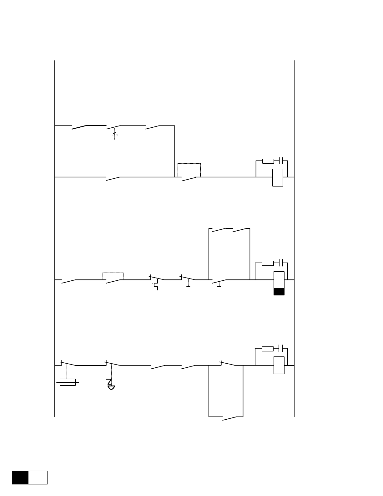
GEI-100332Ga
Emergency
Emergency
K0
K0
Q2
F2
Motor thermal
protection
S11
Off / Stop
S2
On / Start
On / Off
Start / Stop
K2
K2
K2
K1M
Mains line
Note !
Q2 for fans mounted
on drives from 560 / 770 A
(American / European)
L01
L00
35
36
K1M
K1MK0
G1
ok
[P412]
K2
K0
Jumper: emergency braking,
disconnection after the motor
stop
Any jumper: direct disconnection,
the motor ceases to stop
75
76
G1
Stop control
[P629]
t > t
br
G1
from 560 / 770 A
(American / European)
Q1 Control circuit
supply
81
82
K1M
4.8 STANDARD CONNECTION DIAGRAMS
Figure 4.8.1:Control sequencing
4
18
——— WIRING PROCEDURES ———
Page 63

DV-300 Adjustable Speed Drives
H
EXTERNAL
ESTOPS
SNF
STOP
PB
- Time delay after de energization Set greater than the maximum
decel ramp time.
EXTERNAL
RUN
PERMISSIVES
FAST STOP
P.B.
latched on push, pull to reset
after the process has stopped
K2
Blown
Fuse
81
FAN power
OK (Q1)
Contact closes
with power ON
FAN 560A and
above only
115 VAC from CPT
fed from AC incoming
SNF
82
560A and
above only
Reset
Drive Healthy
85
picks up if OK
START
Drive OK
START
K2
PB
K1M AUX
(MA AUX)
86
AC Input Contactor
K1M
System Not Fault
SNF
Drive OK
FAST STOP
K0
START
K2
ENABLE
K1MX
T.D.A.D. *
N
19
+24V
SNF
15
19
K0
14
+24V
19
K2
13
+24V
19
K1MX
ENABLE
12
EXT
FAULT
+24V
FAST
STOP
START
DV-300
Relay 2
75
Operation set by parameter [629]
76
RELAY 2 and parameter [626] stop mode
Coil Suppressor
Figure 4.8.2: Example for relay interface
note! 1 - ENABLE must remained energized during a normal STOP or FAST STOP for the DV-300
to decel on a ramp.
2 - ENABLE must be de energized to power up and to reset a fault or alarm.
3 - If the external fault input, or fast stop input, is unused, the unused input must
be tied to + 24V (terminal 19).
4 - EXTERNAL FAULT input, FAST STOP input, START input and ENABLE input
need picked up during LAN operation. Opening the input will cause labeled drive
reaction.
* - T.D.A.D. = Time Delay After De energization.
——— WIRING PROCEDURES ———
19
4
Page 64

GEI-100332Ga
Digital inputs
Digital outputs
Analog outputs
19
+ 24V
0 V24
* See Figure 4.8.1
18
16
15
14
* K0
13
* K2
12
Start
drive
COM ID
Fault
External
Enable
Analog input 3
Analog input 2
Fast stop
Analog input 1
1 2 3 4
35 31 32 33 34
Supply
1 2 3 4
25 26 27 28 29 30
0 V
+ 24 V
* K1M
1 2
21 22 23 24
M1-M2
5
3
230 VAC
FAN PWR
CNTL PWR
115-230 VAC
5
6
3
4
1
2
1
5
3
1
Q1
Q2
75 76
36
35 (4)
(1)
6
2 4
6
V2
U2
2 4
PE
Relay 2 [P629]
ok [P412]
RS 485
24V
0V
XE2
Keypad
V3
U3
81
W
V
U
B-
B+
A-
A+
(5)
+
-
-+ +
-
2
7
1
8
6
5
SMPS
82
5
6
3
4
W1
1
2
11
0 V
9
0 V 10
8
- 10 V
7
+ 10 V
Rigth
0
6KDV3...Q2
79
78
Left
6KDV3...Q4
Thermistor (3)
PE
PE
(2)
D
F3
C
1B1 2B2
R1 (2 ... 5 kOhm)
(4)
L1L2L3
F11
N
PE
K1M
F2
L1
V1
U1
F12
D1
2F2
C1
1F1
G1
M1
Figure 4.8.3: Typical connections
Typical wiring diagram for the standard conguration of the converter.
It is necessary to follow the instructions for mounting and wiring given in the chapters concerning engineering notes and EMC measures.
Option cards connection is not indicated here.
It is not considered the autorestart of the drive after an alarm condition.
(1) Fan with external supply only above 560/770 A included (American/European).
(2) Fuses only for 6KDV3...Q4 up to 450/650 A (American/European).
(3) 1Kohm resistor connected when the thermistor is not present.
(4) The indicated connections are relative for a digital Encoder.
(5) From 770 A (European) and 560 A (American) sizes.
Connections for sinusoidal encoder and tachogenerator are serately indicated.
20
4
——— WIRING PROCEDURES ———
Page 65

DV-300 Adjustable Speed Drives
XE1
A-
A+
B+ B-
Sinus encoder
R-TPD3-GE
Analog outputs
1 2
0V 5V
15 6 98 7
XE2
A-
A+
B+ B-
0V 24V
15 6 28 7
Digital encoder
Figure 4.8.4: Encoder and Tachometer Connections
Digital outputs
1 2 3 4
Supply
Digital inputs
1 2 3 4
Voltage setting by
S4-1...8
-
T
+
Analog tacho
19 18
0 V 24
+ 24 V
21 22 23 24
25 26 27 28 29 30
37 31 32 33 34
+ 24 V
0 V
Figure 4.8.5: Programmable Inputs/outputs (option 6KCV300TBO) with relay and contacts
note! To improve the noise immunity it is advisable to connect the common of the outputs (termi-
nals 22/24, 25/37 of 6KCV300TBO) with the ground (terminals 10 or 20 of the regulation
board). It is not possible, the above mentioned common have to be grouded by means of a
0,1 µF/250V capacitor.
——— WIRING PROCEDURES ———
21
4
Page 66

GEI-100332Ga
Analog outputs
1 2
21 22 23 24
Digital outputs
1 2 3 4
25 26 27 28 29 30
Supply
R-TPD32-GE
Digital inputs
37 31 32 33 34
1 2 3 4
SPS / PLC
Analog inputs
IA 1
IA2
0 V
ID 1
ID 2
ID 3
ID 4
+ 24 V
Digital Inputs
Digital Outputs
0 V
QD 1
QD 2
QD 3
QD 4
Figure 4.8.6: Programmable Inputs/outputs with PLC
XE1 XE2
1
5
96
XS2
9
7
5
+
S1
A+
8
6
S2
B+
A-
XS
1
1
5
96
1 2 3 4 5 6 7 8 9 10 11 12 13 14 15 16 17 18 19 20
5
96
1,5m
SH
DES
Versorgung Encoder
Supply encoder
Alimentation encoder
Alimentazione encoder
+ 5 V
oder / or / ou / o
+ 15 ... 24 V
1
2
4
3
S4
S3
+ Supp
B-
C-
C+
- Supp
22
4
5
6 8
1 3
Figure 4.8.7: 6KCV300DES connection
——— WIRING PROCEDURES ———
XS1
4
9
7
2
+Venc
0Venc
- +
Page 67

4.9 CIRCUIT PROTECTION
(D)
17 ... 450 A American
4.9.1 Fuses
Fuses of the power section
DV-300 Adjustable Speed Drives
A
U V W
C D
B
U1 V1
C1 D1
M
20 ... 650 A European
D
Note:
These fuses (D)
are internal for
american drives
U V W
C
C D
M
770 ... 1050 A European
560 ... 850 A American
Figure 4.9.1.1: Position of the super fast fuses
U1 V1
C1 D1
D
Note:
These fuses
are internal for
american drives
For protection of the bridge thristors use fast acting fuses. The following recommended fuses are externally
mounted. Models 6KDV3560..., 6KDV3770... and higher, HAVE internally mounted fuses provided (Code C
on table 4.8.1.1).
note! The 6KDV3 ... QB2... and 6KDV3 ...Q4F... Drives (500V AC input supply) have the eld
6KDV3 size up to 56 / 70 A * Bussman FWH-015A6F
6KDV3 size 88 / 110 ... 850 / 1050 A * Bussman FWC 25A10F
Gould Shawmut A60Q25-2
* American / European
converter fuses internally mounted. The fuses type for the different sizes of converter are
the following:
——— WIRING PROCEDURES ———
23
4
Page 68

GEI-100332Ga
Table 4.9.1.1: Recommended fuses (externally mounted)
Code Pieces European European American American
A 3 6KDV3020 Z14gR20 (GRD2/20) 6KDV3017 A70P25
3 Nr. 10 005 07.25 FWP25
B* 2 Z14gR20 (GRD2/20) A70P25
2 Nr. 10 005 07.30 FWP25
D 2 Z14gR20 (GRD2/20) A70P20
2 Nr. 10 005 07.20 FWP20
A 3 6KDV3040 Z22gR50 (GRD3/50) 6KDV3035 A70P40
3 Nr. 10 005 07.50 FWP40
B* 2 Z22gR63 (GRD3/63) A70P50
2 Nr. 10 005 07.63 FWP50
D 2 Z14gR20 (GRD2/20) A70P20
2 Nr. 10 005 07.20 FWP20
A 3 6KDV3070 Z22gR63 (GRD3/63) 6KDV3056 A70P80
3 Nr. 10 007 07.63 FWP80
B* 2 S00UF01/80/100A/660V A70P80
2 Nr. 20 189 20, 80 A FWP80
D 2 Z14gR20 (GRD2/20) A70P20
2 Nr. 10 005 07.20 FWP20
A 3 6KDV3110 SOOUF1/80/100A/660V 6KDV3088 A70P100
3 Nr. 20 189 20.100 FWP100
B* 2 SOOUF1/80/125A/660V A70P150
2 Nr. 20 189 20.125 FWP150
D 2 Z14gR20 (GRD2/20) A70P20
2 Nr. 10 005 07.20 FWP20
A 3 6KDV3140 SOOUF1/80/125A/660V 6KDV3112 A70P150
3 Nr. 20 189 20.125 FWP150
B* 2 SOOUF1/80/160A/660V A70P175
2 Nr. 20 189 20.160 FWP175
D 2 Z14gR20 (GRD2/20) A70P20
2 Nr. 10 005 07.20 FWP20
A 3 6KDV3185 SOOUF1/80/200A/660V 6KDV3148 A70P175
3 Nr. 20 189 20.200 FWP175
B* 2 SOOUF1/80/200A/660V A70P200
2 Nr. 20 189 20.200 FWP200
D 2 Z14gR20 (GRD2/20) A70P20
2 Nr. 10 005 07.20 FWP20
A 3 6KDV3280 S1UF1/110/250A/660V 6KDV3224 A70P300
3 Nr. 20 458 20.250 FWP300
B* 2 S1UF1/110/315A/660V A70P350
2 Nr. 20 458 20.315 FWP350
D 2 Z14gR32 (GRD2/30) A70P30
2 Nr. 10 005 07.30 FWP30
A 3 6KDV3350 S1UF1/110/315A/660V 6KDV3280 A70P350
3 Nr. 20 458 20.315 FWP350
B* 2 S2UF1/110/400A/660V A70P400
2 Nr. 20 459 20.400 FWP400
D 2 Z14gR32 (GRD2/30) A70P30
2 Nr. 10 005 07.30 FWP30
24
4
——— WIRING PROCEDURES ———
Page 69

DV-300 Adjustable Speed Drives
Code Pieces European Europe American American
A 3 6KDV3420 S2UF1/110/400A/660V 6KDV3336 A70P400
3 Nr. 20 459 20.400 FWP400
B* 2 S2UF1/110/500A/660V A70P500
2 Nr. 20 459 20.500 FWP500
D 2 Z14gR32 (GRD2/30) A70P30
2 Nr. 10 005 07.30 FWP30
A 3 6KDV3500 S2UF1/110/500A/660V 6KDV3400 A70P500
3 Nr. 20 459 20.500 FWP500
B* 2 S2UF1/110/630A/660V A70P600
2 Nr. 20 459 20.630 FWP600
D 2 Z14gR32 (GRD2/30) A70P30
2 Nr. 10 005 07.30 FWP30
A 3 6KDV3650 S2UF1/110/630A/660V 6KDV3450 A70P600
3 Nr. 20 4595 20.630 FWP600
B* 2 S3UF1/110/710A/660V A70P700
2 Nr. 20 460 20.710 FWP700
D 2 Z14gR32 (GRD2/30) A70P30
2 Nr. 10 005 07.30 FWP30
C** 3 6KDV3770Q2 170M5464/800A/660V 6KDV3560Q2 170M5464/800A/660V
A2-66C800TS A2-66C800TS
D 2 Z14gR32 (GRD2/30) A70P30
2 Nr. 10 005 07.30 FWP30
C** 6 6KDV3770Q4 170M5462/630A/660V 6KDV3560Q4 170M5462/630A/660V
A2-66C630TS A2-66C630TS
D 2 Z14gR32 (GRD2/30) A70P30
2 Nr. 10 005 07.30 FWP30
C** 3 6KDV310H 170M5464/1000A/660V 6KDV3800 70M5464/1000A/660V
A2-66C1000TS A2-66C1000TS
D 2 Z14gR32 (GRD2/30) A70P30
2 Nr. 10 005 07.30 FWP30
C** 6 6KDV310H 170M5464/800A/660V 6KDV3850 170M5464/800A/660V
A2-66C800TS A2-66C800TS
D 2 Z14gR32 (GRD2/30) A70P30
2 Nr. 10 005 07.30 FWP30
GD0290g
* Necessary only for the four quadrant functioning
** These fuses are internally mounted and are provided on the delivery
A External fuses for the armature converter on the AC input side
B External fuses for the armature circuit on the direct current side
C Internal armature fuses for the device starting from type 560A / 770A (American/European)
D External fuses for the eld circuit on the AC input side.
Note: These fuses are necessary only for 6KDV3...Q2A/Q4E Internal fuses are provided for 6KDV3...Q2B/Q4F.
note! When with the same letter different fuses are stated, it means that they can be used alternati-
vely. The different types differ for the building forms and for the production house. See the
following indications.
Fuses producer: Type Z14gR..., GRD2... (E27), Z22gR..., GRD3... (E33)
S... (screw fuses with a distance 80 or 110 mm) Jean Müller, Eltville
A70P, A2-66C Gould Shawmut
FWP..., 170 M Bussmann
note! The fuse technical data (dimensions, weights, dissipated powers, fuses carrier etc.), can be
derived from the relative data sheets.
——— WIRING PROCEDURES ———
25
4
Page 70

GEI-100332Ga
4.9.2 Fuses selection when the Overload function is activated
> 100% for 60 seconds - European > 150% for 60 seconds - American
The fuses suitable for the max Overload capacity of each converter are listed in the following table.
Table 4.9.2.1: Overload fuses
Converter Code Pieces 400 VAC Input supply 500 VAC Input Supply
6KDV3017
6KDV3020
6KDV3035
6KDV3040
6KDV3056
6KDV3070
6KDV3088
6KDV3110
6KDV3112
6KDV3140
6KDV3148
6KDV3185
6KDV3224
6KDV3280
6KDV3280
6KDV3350
6KDV3336
6KDV3420
6KDV3400
6KDV3500
A 3 Z14gR25 (GRD2/25) Z14gR25 (GRD2/25)
3 Nr. 10 005 07.25 Nr. 10 005 07.25
B* 2 Z14gR32 (GRD2/30) Z14gR32 (GRD2/30)
2 Nr. 10 005 07.30 Nr. 10 005 07.30
A 3 Z22gR50 (GRD3/50) Z14gR40 (GRD3/35)
3 Nr. 10 005 07.50 Nr. 10 005 07.35
B* 2 Z22gR63 (GRD3/63) Z22gR50 (GRD3/50)
2 Nr. 10 005 07.63 Nr. 10 005 07.50
A 3 Z22gR80 (GRD4/80) S00UF01/80/100A/660V
3 S00UF1/80/80A/660V S00UF01/80/100A/660V
3 S00UF01/80/100A/660V
3 Nr. 20 189 20, 80 A Nr. 20 189 20, 80 A
B* 2 Z22gR100 (GRD4/100) Z22gR100 (GRD4/100)
2 S00UF1/80/100A/660V S00UF1/80/100A/660V
2 S00UF1/80/125A/660V
2 Nr. 20 189 20,100 A Nr. 20 189 20,100 A
A 3 S00UF1/80/100A/660V S00UF1/80/100A/660V
3 Nr. 20 189 20.100 Nr. 20 189 20.100
B* 2 S00UF1/80/125A/660V S00UF1/80/125A/660V
2 Nr. 20 189 20.125 Nr. 20 189 20.125
A 3 S00UF1/80/160A/660V S00UF1/80/160A/660V
3 Nr. 20 189 20.160 Nr. 20 189 20.160
B* 2 S00UF1/80/200A/660V S00UF1/80/200A/660V
2 Nr. 20 189 20.200 Nr. 20 189 20.200
A 3 S00UF1/80/200A/660V S00UF1/80/200A/660V
3 Nr. 20 189 20.200 Nr. 20 189 20.200
B* 2 S00UF1/80/200A/660V S00UF1/80/200A/660V
2 Nr. 20 189 20.200 Nr. 20 189 20.200
A 3 S1UF1/110/315A/660V S1UF1/110/315A/660V
3 S1UF1/110/350A/660V S1UF1/110/350A/660V
3 Nr. 20 458 20.315 Nr. 20 458 20.315
B* 2 S2UF1/110/400A/660V S2UF1/110/400A/660V
2 S2UF1/110/400A/660V S2UF1/110/400A/660V
2 Nr. 20 459 20.400 Nr. 20 459 20.400
A 3 S1UF1/110/400A/660V S1UF1/110/400A/660V
3 S1UF1/110/450A/660V S1UF1/110/450A/660V
3 Nr. 20 459 20.400 Nr. 20 459 20.400
B* 2 S2UF1/110/500A/660V S2UF1/110/500A/660V
2 S2UF1/110/500A/660V S2UF1/110/500A/660V
2 Nr. 20 459 20.500 Nr. 20 459 20.500
A 3 S2UF1/110/500A/660V S2UF1/110/500A/660V
3 Nr. 20 459 20.500 Nr. 20 459 20.500
B* 2 S2UF1/110/630A/660V S2UF1/110/630A/660V
2 Nr. 20 459 20.630 Nr. 20 459 20.630
A 3 S2UF1/110/630A/660V S2UF1/110/630A/660V
3 S2UF01/110/710A/660V
3 Nr. 20 459 20.630 Nr. 20 459 20.630
B* 2 S3UF1/110/710A/660V S3UF1/110/710A/660V
2 S3UF1/110/710A/660V S3UF1/110/710A/660V
2 Nr. 20 460 20.710 Nr. 20 460 20.710
26
4
——— WIRING PROCEDURES ———
Page 71

DV-300 Adjustable Speed Drives
Converter Code Pieces 400 VAC Input supply 500 VAC Input Supply
A 3 S2UF1/110/630A/660V S2UF1/110/630A/660V
6KDV3450
6KDV3650
A External fuses for the armature circuit on the DC side
B External fuses for the armature converter on the AC input side
* Necessary only for the four quadrant functioning
Note for sizes 6KDV3770 ... 6KDV310H: the armature fuses are internally mounted (see table 4.9.1.1)
B* 2 S3UF1/110/710A/660V S3UF1/110/710A/660V
3 S2UF01/110/710A/660V
3 Nr. 20 459 20.630 Nr. 20 459 20.630
2 S3UF1/110/710A/660V
2 Nr. 20 460 20.710 Nr. 20 460 20.710
4.9.3 Internal Fuses
Table 4.9.3.1: Internal fuses
Converter Designation Fuses for Fuse Mounted on
6KDV3017 - 3148
6KDV3020 - 3185
6KDV3224 - 3450
6KDV3280 - 3650
6KDV3560 - 3850
6KDV3770 - 310H
F1
F1
F2
F1/F2/F3
+ 24V
power supply out
+ 24V
power supply out
+ 24V
power supply in
Varistor fuse
Varistor fuse
IEC 250 V 1 A slo-blo
0.2” x 0.8” (5 x 20 mm)
IEC 250 V 3.15 A fast acting
0.2” x 0.8” (5 x 20 mm)
IEC 250 V 2.50 A slo-blo
0.2” x 0.8” (5 x 20 mm)
IEC 500 V 16 A fast acting
0.24” x 1.26” (6 x 32 mm)
IEC 500 V 25 A fast acting
0.24” x 1.26” (6 x 32 mm)
GD0300-1g-2g
SW1-31
SW2-32
SW3-32
SW2-31
FL-31
GD0310g
Replacement vendor sources - equivalent to meet above rating
F1 1 A Omega (Europe) ST 520210 Littlefuse 218 001 (Littlefuse 239 1.25 may also be substituted).
F1 3.15 A Omega (Europe) SF 520231 Littlefuse 217 3.15
F2 2.5 A Omega (Europe) ST 520225 Littlefuse 218 2.5
F... 16 A Omega (Europe) FF 632316 Cooper/Bussman FWH-016A6F
F... 25 A Omega (Europe) FF 632325 Cooper/Bussman FWH-025A6F
Internal eld exciter fuse (American version only; for “standard” version the fuses are externally mounted).
Device Internal eld exciter fuse
Quantity Fuse Type Producer
6KDV3017 - 3148 2 pieces 500 V 15 A fast FWH-015a6F Cooper/Bussman P/N
6KDV3224 - 3850 2 pieces 500 V 25 A fast FWH-025a6F Cooper/Bussman P/N
GD0314g
——— WIRING PROCEDURES ———
27
4
Page 72

GEI-100332Ga
4.9.4 AC input contactors
note! The contactor sizes must be selected based on the converter rated current. The dimensions
basis is the thermo current AC1, which is absorbed by the input during the rated functioning.
note! The technical data of the contactors, as for example weights, dissipated powers, auxiliary
contacts etc. can be found in the appropriate data sheets.
4.9.5 Control power protection
The 115 VAC/230 VAC control power input, U2 & V2, for the DV-300 are required to be short circuit protected.
This protection can be provided by using standard time delay fuses, or circuit breaker.
The circuit breaker and/or time delay fuses must be selected to survive the short circuit available current of the
feeder source for this circuit, and the inrush current of the drive power supply.
The rating of the fuses or circuit breaker should be sized mainly to protect the wiring from the fuses/circuit
breaker connections to U2 & V2, and not nuisance trip or blow from the inrush current.
The table below, Table 4.9.5, lists the input current characteristics of the control power.
Table 4.9.5: Control power protection
Device Regulation Power Supply
American European Card Power
6KDV3017
to ...
6KDV3148
6KDV3224
to ...
6KDV3850
6KDV3020
to ...
6KDV3185
6KDV3280
to ...
6KDV310H
SW1-31 60 W 1 A 0.5 A 20 A 10 A
SW2-32 110 W 1.2 A 0.7 A 15 A 7.5 A
Rated input current Inrush input current
115 V 230 V 115 V 230 V
GD0315g
The control power input is best served by a power source that is stabilized and buffered from the power system transients.
The control power of many drives can be fed from a single source, as long as proper distribution protection is provided.
For example, a 6KDV3017, with 480VAC input, has control power fed from a 2 KVA 480:115 transformer that
is panel mounted in the drive panel. The transformer primary is wired from the 480VAC drive incoming power
from the load side of the main power disconnect and is fused with Fusetron 600 V 5A FRS fuses. The wires from
the transformer secondary to the drive connection points U2 & V2 are 12 AWG.
No additional circuit protection is required, and control power is disconnected when the main power disconnected is off.
If the 2KVA transformer was mounted in a remote panel, a 250V/120V 10A 5kA interrupting CB could be panel
mounted near the Drive to locally turn off the Drive control panel.
28
4
——— WIRING PROCEDURES ———
Page 73

DV-300 Adjustable Speed Drives
4.10 REACTORS / FILTERS
In order to provide AC line protection from transients and high frequencies, it is necessary to insert a threephase
reactor on the AC input of the DV-300. The values here stated take into consideration the recommendation per
EN 60146-1-1, IEC 146-1-2, EN 61136-1.
The reactors can be provided by means of line reactors or an isolation transformer.
4.10.1 AC input choke
The type of the required AC input choke depends on
- the current absorbed by the AC input
- the AC input voltage
- the relative short circuit voltage
- the AC input frequency
The values stated in the following tables refer to a functioning with the connected converter rated current and
with a relative short circuit voltage of uk = 4 %. The saturation current of the reactors is 200% of the full load
current rating of the reactor.
In case of functioning with a motor having a rated current lower than the converter one it is possible to choose
the main reactor on the basis of the motor current stated on the AC input side (armature current x 0.82 x 1.05).
The reactor saturation current can also be calculated according the required motor overload.
Example: calculating the AC input choke
Motor: Va = 400V Ia = 80 A P = 29.4 kW Overload 150% Ia
Converter 6KDV3110Q2A.../Q4A...
AC input current: I
AC input inductance:
= Ia · 0.82 · 1.05 = 80 · 0.82 · 1.05 = 68.9 A
mains
L = = = 0.427 mH
0.04 . V
3 . 2 . f . I
mains
mains mains
0.04 . 400
3 . 2 . 50 . 68.9
Choke saturation
current: I
= 1.5 I
sat
= 103.3 A
mains
29
——— WIRING PROCEDURES ———
4
Page 74

GEI-100332Ga
Table 4.10.1.1: AC input choke
Main three-phase inductance
Converter
Main 400 V, 3Ph, 50 Hz
6KDV3020Q2A.../Q4E... 1,71 17,2 34,4 50 KLR18CTB
6KDV3040Q2A.../Q4E... 0,855 34,4 68,8 50 KLR45CTB
6KDV3070Q2A.../Q4E... 0,488 60,2 120,4 50 KLR80CTB
6KDV3110Q2A.../Q4E... 0,311 94,6 189,2 50 KLR110CCB
6KDV3140.Q2A.../Q4E... 0,244 120,4 240,8 50 KLR160CCB
6KDV3185Q2A.../Q4E... 0,185 159 318 50 KLR300CCB
6KDV3280Q2A.../Q4E... 0,122 241 482 50 KLR300CCB
6KDV3350Q2A.../Q4E... 0,098 301 602 50 KLR360CCB
6KDV3420Q2A.../Q4E... 0,081 361 722 50 KLR420CCB
6KDV3500Q2A.../Q4E.... 0,068 430 860 50 KLR600CCB
6KDV3650Q2A.../Q4E.... 0,053 559 1118 50 KLR750CCB
6KDV3770Q2A.../Q4E.... 0,044 662 1324 50 KLR750CCB
6KDV310HQ2A.../Q4E.... 0,034 860 1720 50 KLR1250C
6KDV310HQ2A.../Q4E... 0,033 903 1806 50 KLR1250C
Main 460 V, 3Ph, 60 Hz
6KDV3017Q2B.../Q4F... 1,933 14,6 29,2 60 KLR18CTB
6KDV3035Q2B.../Q4F... 0,938 30,1 60,2 60 KLR45CTB
6KDV3056Q2B.../Q4F... 0,586 48,2 96,4 60 KLR80CTB
6KDV3088Q2B.../Q4F... 0,373 75,8 151,6 60 KLR110CCB
6KDV3112.Q2B.../Q4F... 0,293 96,4 193 60 KLR160CCB
6KDV3148Q2B.../Q4F... 0,227 127,4 255 60 KLR160CCB
6KDV3224Q2B.../Q4F... 0,146 193 386 60 KLR300CCB
6KDV3280Q2B.../Q4F... 0,117 241 482 60 KLR300CCB
6KDV3336Q2B.../Q4F... 0,098 289 578 60 KLR360CCB
6KDV3400Q2B.../Q4F.... 0,082 344 688 60 KLR420CCB
6KDV3450Q2B.../Q4F.... 0,073 387 774 60 KLR600CCB
6KDV3560Q2B.../Q4F.... 0,058 482 964 60 KLR600CCB
6KDV3800Q2B.../Q4F.... 0,041 689 1378 60 KLR1250C
6KDV3850Q2B.../Q4F... 0,038 732 1464 60 KLR1250C
Rated
choke [mH]
Rated ac
current [A]
Saturation
Freq. [Hz] Model No.
current [A]
GD0330g
4.10.2 Interference suppression filters
The converters of DV-300 series must be equipped with an external EMI lter in order to reduce the radiofrequency emissions on the mains line. The lter selection is depending on the drive size and the installation
environment. For this purpose see the “EMC Guidelines”.
In the Guide it is also indicated how to install the cabinet (connection of lter and mains reactors, cable shields,
grounding, etc.), in order to make it EMC compliant according the EMC Directive 89/336/EEC.
The document describes the present situation concerning the EMC standards and the compliance tests made on
the GE drives.
30
4
——— WIRING PROCEDURES ———
Page 75

4.11 ENGINEERING NOTES
TBO
Analog outputs
1 2
1 2 3 4
Digital outputs
1 2 3 4
5 6 7 8 9 10
Supply
Digital inputs
15 11 12 13 14
1 2 3 4
1 2 3 4 5 6
Analog inputs
12
13
14
15
16
Enables
11
XE 2
7
2
19
18
+ 24 V
0 V 24
9
0 V 10
+ 10 V
- 10 V
7
8
Reference Supply dig. I/O
R-TPD3
XE 1
7
9
+ 15 V
+ 5 V
± 15 V
Sinusencoder
Digitale encoder
0 V
0 V
Figure 4.11.1: Potentials of the regulator section
DV-300 Adjustable Speed Drives
Potentials of the regulator section
The potentials of the regulator section are galvanic divided from the power section. Figure 4.11.1 shows their
connection.
- The analog inputs are designed as differential.
- The enables are isolated from the regulation via optoisolators. The terminals 12 to 15 have terminal 16 as a
- The internal potential 0V is connected to terminal 11. In the majority of the cases the interference suppres-
- The regulation card puts at your disposal the following power supplies, which have a common reference
+ 10V and - 10V for the reference
+ 24V for the power supply of the digital inputs and outputs
+ 5V for the encoder power supply
- The analog outputs are divided from the internal potential through a differential amplier. The two outputs
- The digital outputs have the same potential (terminal 37) but they are divided from the regulator internal
- The digital inputs are divided from the regualtor through optoisolators. The terminals 31 to 34 have terminal
common reference potential.
sion is decreased!
point:
of the option card have the same potential (terminal 22 and 24 of 6KCV300TBO option card). When the
6KCV300TBO option card is used, the potential of the analog outputs are divided. For a better interference
suppression and for the “cleaning” of the output signals, the terminals 22 and 24 of the 6KCV300TBO option
31
card are directly ground connected (terminal 10 and /or 20 of the R-TPD3 card) or via a 0.1µF/250V capacitor.
potential via optoisolators. In order to use the outputs, it is necessary to connect a power supply voltage to
the terminal 30.
37 as a common potential.
——— WIRING PROCEDURES ———
4
Page 76

GEI-100332Ga
External devices
As for the installation of contactors, protection devices, chokes, lters and other external devices it is necessary to follow the indication given in the previous chapters. The same theory is valid for motors, encoders and
tachometers.
Connection cables
The encoder shielded cable must be made of twisted pairs. The connection cables of the encoders and of the
motors, if possible, should be connected directly to the device, without going through support terminal strips.
The shieldings of the signal conductors have to be ground connected on both sides. Anyway, for all analog and
digital signals with very long connections (outside the electric board), it is suggested to have a ground connection only on the converter side, in order to avoid possible noises caused by the closing of the ground loops. In
particular cases it could be necessary to connect the shielding on both sides, thus granting the point equipotentiality via suitable connection cables.
The encoder cable has to be made up of twisted loops with the global shielding connected to the ground on the
converter side. Avoid to connect the shielding on the motor side connector. In particular cases (cable longer than
100 meters, strong electromagnetic noise), it could be necessary to use a cable with a shielding on every loop to
be connected to the power supply ground. The global shielding has always to be ground connected.
32
4
——— WIRING PROCEDURES ———
Page 77

5.1 KEYPAD
DV-300 Adjustable Speed Drives
5 - CONVERTER OPERATION
The keypad is made of a LCD display with two 16-digit lines and 8 function buttons. It is used
- to command the drive when this system has been selected
- to display the speed, the voltage and diagnostics during the operating time
- to set parameters
5.1.1 LEDs
The leds present on the keypad are used to diagnose in a fast way the functioning situation of the converter.
Designation Color Function
- Torque yellow the LED is lit, when the drive operates with a negative torque
(anti-clockwise rotation or clockwise braking). Only for 6KDV3...Q4.
+ Torque yellow the LED is lit, when the drive operates with a positive torque
(clockwise rotation or anti-clockwise braking). Braking only for 6KDV3...Q4.
Alarm red the LED is lit, it signals the intervention and the alarm condition
Enable green the LED is lit, when the converter is enabled
Zero Speed yellow the LED is lit, when the motor speed is lower than the threshold set by Speed zero level
I Limit yellow the LED is lit, when the converter operates at a current limit
GD0020g
——— CONVERTER OPERATION ———
1
5
Page 78
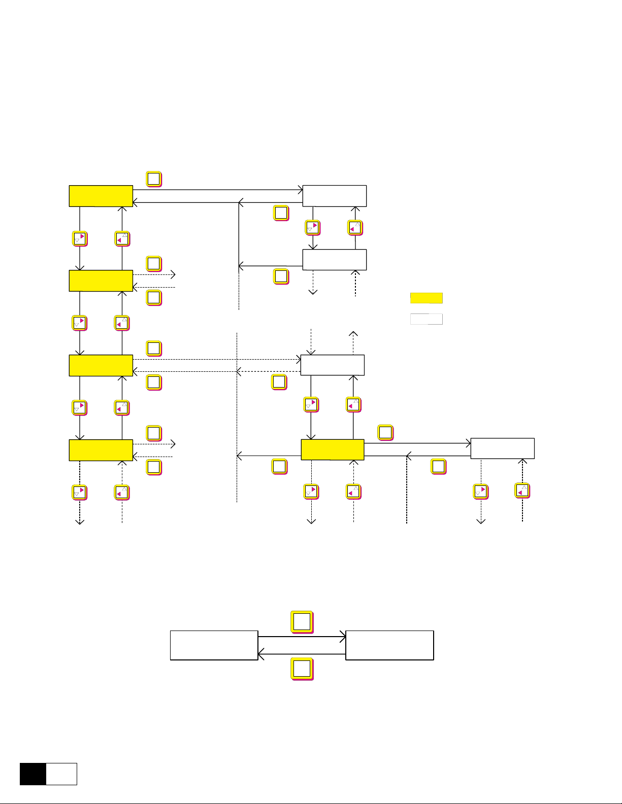
GEI-100332Ga
5.1.2 Moving inside a menu
- The DRIVE STATUS always appears when the converter is switched on.
- Use the ▲ and ▼ keys to select the individual points within the same menu level.
- Press the ENT key to enter the next menu level.
- Use the CANC key to return to the next higher menu level, irrespective of which menu point was selected.
The appropriate menu of the next higher level will appear once the return has been made.
Main menu
DV-300
DRIVE STATUS
DV-300
START UP
DV-300DV-300
TUNING
DV-300
MONITOR
ENT
3rd level2nd level
DRIVE STATUS
Ramp ref 1
CANC
DRIVE STATUS
ENT
CANC
CANC
ENT
CANC
ENT
CANC
CANC
CANC
Enable Drive
TUNING
Start/Stop
TUNING
Speed self tune
Menu
Parameter
ENT
Speed self tune
Fwd-Rev spd tune
CANC
Figure 5.1.2.1: Moving inside a menu
5.1.3 Displaying parameters
ENT
Measurements
Mains voltage
CANC
- Select the parameters within the menu
- Press ENT. The parameter with its relative value will appear.
- Return to the menu using CANC.
2
5
——— CONVERTER OPERATION ———
Mains voltage
403 [V]
Page 79

DV-300 Adjustable Speed Drives
5.1.4. Changing / Saving parameters / Password
The parameters with changeable values are divided into three groups:
- Pa ram eters whose cont ent is either selected as a numb er or as text within a defined ran ge
e.g. ramp times and reference values
- Parameters whose contents are xed values that can be selected.
e.g. Jog selection with the “speed input” and “Ramp input” alternatives.
- Parameters that are automatically scaled by the keypad
e.g. Auto tune inp XX
note! Only those parameters that are not assigned to a digital or analog input/output can be changed
with the keypad. The changed parameters must be saved otherwise the previous values will
be loaded the next time the device is switched on.
Changing numerical values and text
START UP
Speed feedback
ENT
CANC
Speed feedback
Encoder 2 pulses
0 ... 9
ENT
9 ... 0
Encoder 2 pulses
1 0 2 4
+
-
ok
Return without changes
ENT
CANC
- Select within the menu the parameters to be changed.
- Press ENT. The value of the parameter will appear and the last digit will ash. The value of the ashing digit
is always the one that can be changed.
- Increase the value with +
- Reduce the value with -
- Select the next digit left with
- Select the next digit right with
- Conrm the new value and return to the previous display by pressing ENT.
- Press CANC to return without changes.
note! When setting the Dim factor text parameter, the following characters are also available in
addition to the numbers: / % & + , - . : < = > ? A...Z [ ] a...z
——— CONVERTER OPERATION ———
3
5
Page 80

Selection from predefined values
GEI-100332Ga
FLUX REGULATION
Flux reg mode -/+
ENT
Flux reg mode -/+
Constant current
+
Flux reg mode -/+
Field weakening
+
Flux reg mode -/+
OFF
ok
Return without changes
-
ok
Return without changes
-
ok
Return without changes
ENT
CANC
ENT
CANC
ENT
CANC
- The parameters that can be selected among the several possiblities are marked with -/+ on the keypad display.
- To change a value press ENT. The current value is shown in the display. This can be changed with the +
and - keys.
- Conrm the new value and return to the previous display by pressing ENT.
- Return without changes via CANC
Autotuning of Analog input
ENT
Analog input 1
Auto tune inp 1
- Select the parameter Auto tune input XX.
- Press ENT
- The tuning procedure will run automatically. The messages “Tuning” and “Ready” will appear in succession
before the original parameter is shown.
note! The maximum signal possible must be present on the analog input concerned during the
tuning procedure.
4
5
——— CONVERTER OPERATION ———
Auto tune inp 1
Tuning
Auto tune inp 1
Ready
Page 81

DV-300 Adjustable Speed Drives
Parameters Saving
The parameters must be saved, otherwise the previous values will be loaded the next time the device is switched on.
ENT
START UP
Save parameters
Save parameters
Wait...
Write ok
- Select Save parameters in the START UP or in the SPEC FUNCTIONS menu.
- Press ENT
- The saving operation is automatic. The messages “Wait ...” and “Write ok” will appear in succession before
the original parameter is shown.
Entering a password
The operator can dene a password consisting of a freely selectable ve-digit number combination in order to
protect the keypad from unauthorized access. This is carried out via the Pword 1 parameter.
CONFIGURATION
Pword 1: Disabled
CONFIGURATION
Pword 1: Enabled
0 ... 9
9 ... 0
ENT
Pword 1: Disabled
Password 0 0 0 0 0
+
-
ENT
ok
Return without changes
CANC
Pword 1: Enabled
Password 0 0 0 0 0
- Select Pword1 (= Password 1) in the CONFIGURATION menu.
- Press ENT. The value 00000 will appear with the last digit ashing. The value of the ashing digit is
changed.
- Increase the numerical value with +
- Reduce the numerical value with -
- Select the next digit left with
- Select the next digit right with
- Conrm the password by pressing ENT. The message: Pword1: Enabled will then appear shortly with the
currently valid password displayed.
- The existing password is indicated in the CONFIGURATION menu via the “Pword 1: Enabled” message.
- Press the CANC key in order to abort the entry of the password.
note! The password must be saved with Save parameters so that it is also active the next time the
device is switched on.
——— CONVERTER OPERATION ———
5
5
Page 82

General unlocking of the password
GEI-100332Ga
0 ... 9
Password ok
Pword 1: Disabled
Password 0 0 0 0 0
+
CONFIGURATION
Pword 1: Enabled
CONFIGURATION
Pword 1: Disabled
9 ... 0
ENT
Pword 1: Enabled
Password 0 0 0 0 0
-
Return without changes
ENT
Password incorrect
Pword 1: Enabled
Password Wrong
CANC
- Select the parameter Pword1 (= Password 1) in the CONFIGURATION menu.
- When the password is enabled, the message “Pword 1: Enabled” appears
- Press ENT to call the value 00000 with the last digit ashing. The value changed is always the digit that is
ashing. The valid password must be re-entered in order to unlock it.
- Increase the numerical value with +
- Reduce the numerical value with -
- Select the next digit left with
- Select the next digit right with
- Conrm the password by pressing ENT. The message: Pword1: Enabled will then appear for a short time.
- The existing password is indicated in the CONFIGURATION menu via the “Pword 1: Enabled” message.
- Press the CANC key in order to abort the entry of the password if required.
- If the incorrect password is entered and then the ENT key pressed, the message “Password wrong” will appear and the keypad will return to the CONFIGURATION menu with the display “Pword1: Enabled”
note! The Save parameter function must be used to save the password if the password itself must
not only be disabled but completely unlocked.
5.1.5 Operating the drive via the Keypad
In order to operate the drive via the keypad, the following settings must be done :
START UP and CONFIGURATION menu Set Main commands = Digital
MENU CONFIGURATION Set Control Mode = Local
- The hardware enables on terminals 12...15 are also active when the drive is operated via the keypad. This
means, for example, that the signal at terminal 13 must also be present for starting the drive in adddition to
the command via the keypad.
- If the drive is stopped via the keypad, it can be restarted simply by pressing the Start Key.
6
5
——— CONVERTER OPERATION ———
Page 83

DV-300 Adjustable Speed Drives
ENT
START UP
Enable drive -/+
Enable drive -/+
Disabled
+
ENT
Enable drive -/+
Enabled
ENT
START UP
Enable drive -/+
Enable drive -/+
Enabled
ENT
Enable drive -/+
Disabled
-
STOP
START
- If the stop was caused by removing the voltage signal on terminal 13, both the signal at terminal 13 and
the command via the keypad are necessary to restart the drive. The signal at the terminals must be present
before giving the keypad command.
- The same applies accordingly to the enabling of the drive via the Enable drive parameter.
5.1.5.1 Starting and stopping the drive
note: The keypad must be enabled (see section 6.11.1) before performing these actions.
Enabling the converter
- Select the parameter Enable drive in the DRIVE STATUS or START UP or MONITOR menu.
- Press ENT
- Use the key + to choose “Disabled” or “Enabled”.
- Press ENT to conrm your entry.
Disabling the converter
- Select the parameter Enable drive in the DRIVE STATUS or START UP or MONITOR menu.
- Press ENT
- Use the key - to change the display from “Enabled” into “Disabled”.
- Press ENT to conrm your entry.
Start / Stop
Warning: The keypad STOP can be used only when MAIN COMMANDS parameter is set to
digital.
- Start: press the Start key.
- Stop: press the STOP key.
——— CONVERTER OPERATION ———
7
5
Page 84

GEI-100332Ga
ENT
SPEC FUNCTIONS
Failure register
Failure register
External fault
ENT
Failure register
237 hours 45 min
CANC
+
-
Failure register
Undervoltage
ENT
Failure register
76 hours 23 min
+
-
Failure register
Overtemp motor
ENT
Failure register
8 hours 06 min
+
-
max 10
CANC
CANC
ENT
SPEC FUNCTIONS
Failure reg del
Failure reg del
Ready
5.1.5.2 Failure register / Acknowledging alarms
Display of the failure register
- Select the parameter Failure register in the SPEC FUNCTIONS menu.
- Press ENT. The last error that has occurred will be displayed.
- Using the key + it is possible to display the previous alarm.
- The failure register can take up to 10 values. If a new failure is reported, the oldest entry in the failure register
is overwritten.
- The entries in the failure register are retained until the register is cleared.
- Pressing ENT the time when the alarm occurred will be displayed. The time refers to the converter functioning period (presence of the supply voltage).
- After displaying, the menu goes back automatically to the Failure register point.
- By pressing the key CANC during the alarm display, the intervention time is not shown but on the contrary
you go back to the Failure register menu.
Clearing the failure register
- Select the parameter Failure reg del in the SPEC FUNCTIONS menu.
- Press ENT. The failure register is cleared.
5
8
——— CONVERTER OPERATION ———
Page 85

DV-300 Adjustable Speed Drives
External fault
XXXXXXXXXX
( MENU )
XXXXXXXXXX
CANC
External fault
Multi failures
SPEC FUNCTIONS
Failure reset
ENT
Motor pot
Motor pot oper
-
+
Accelerate
Decelerate
CANC
ENT
Motor pot oper
985 [rpm]
Acknowledging a failure alarm
- If a failure occurs, the appropriate failure alarm will appear in the display and the message will ash.
- Acknowledge or reset the failure by pressing the CANC key. The converter must be disabled for this and a
Start command must not be present.
Acknowledging when several failure alarms occur at the same time
- When several failure alarms occur at the same time, the blinking message “Multi failures” will appear in the
display.
- Select the parameter Failure reset in the SPEC FUNCTIONS menu.
- Press the CANC key to acknowledge or reset the failure alarm. The converter must be disabled for this and
there should be no Start command present.
5.1.5.3 Motor potentiometer function
note! To use the motor potentiometer function, this must be enabled with the Enable motor pot
parameter!
Acceleration, Deceleration
- Select the Motor pot oper parameter in the “Motor pot” submenu.
- Pressing ENT the current reference value is displayed.
- Press the + key to increase the reference value and accelerate the drive.
- Press the - key to decrease the reference value and decelerate the drive. This applies to both rotation direc-
tions.
- Press CANC to return to the “Motor pot” submenu.
——— CONVERTER OPERATION ———
9
5
Page 86

GEI-100332Ga
Motor pot
Motor pot sign
-
+
Clockwise
(positive)
Anti-clockwise
(negative)
ENT
Motor pot sign
positive
ENT
Motor pot
Motor pot reset
ENT
Reference value = 0
Jog function
Jog operation
-
+
Jog forward
(clockwise)
Jog backward
(anti-clockwise)
CANC
ENT
Jog operation
137 [rpm]
Changing rotation direction
- Select the Motor pot sign parameter in the “Motor pot” submenu.
- Pressing ENT the current rotation direction is displayed.
- Press the + key to select clockwise rotation and the - key for counterclockwise rotation.
- Conrm by pressing ENT.
- Changing the Motor pot sign parameter during operation causes the drive to reverse rotation according to
the ramp times set.
Resetting the speed reference value
- Select the Motor pot reset parameter in the “Motor pot” submenu.
- Press ENT. The reference speed is set to zero.
note! The speed reference value can only be reset when the drive is switched off.
5.1.5.4. Jog function
note! The Jog function must be enabled via the Enable jog parameter!
5
- Select the Jog operation parameter in the “Jog function” submenu.
- Press ENT. The selection Jog function is displayed.
- Press the + key to select clockwise rotation and the - key for counterclockwise rotation.
- Press CANC to return to the “Jog function” submenu.
10
——— CONVERTER OPERATION ———
Page 87

DV-300 Adjustable Speed Drives
5.2. MENU STRUCTURE
The menu consists of a main menu with submenus and parameters. The structure can be compared to the orga-
nization of les and subdirections on a PC.
DV-300 main menu corresponds PC main menu (main menu = Root)
DV-300 submenu corresponds to PC submenu
DV-300 parameter corresponds to individual parameters
The menu structure is described in the function description given in section 6, “Function description”. The following conventions apply:
Main menu: Black eld, text in capitals
Submenu: Black eld
Parameter White eld
DRIVE STATUS
START UP
TUNING
MONITOR
INPUT VARIABLES
LIMITS
RAMP
SPEED REGULAT
CURRENT REGULAT
FLUX REGULATION
REG PARAMETERS
CONFIGURATION
I/O CONFIG
ADD SPEED FUNCT
FUNCTIONS
SPEC FUNCTIONS
OPTIONS
DRIVECOM
SERVICE
DV0360I
——— CONVERTER OPERATION ———
11
5
Page 88

DRIVE STATUS
START UP
GEI-100332Ga
[44] Ramp ref 1 [FF]
[314] Enable drive
[315] Start/Stop
[233] Output voltage [V]
[199] Motor current [%]
[122] Actual spd (rpm)
[118] Speed ref (rpm)
[1052] Output power [kW]
[351] Flux current (A)
[466] Mains voltage [V]
Digital I/Q
[45] Speed base value [FF]
[374] Nom ux curr [A]
[499] Speed-0 f weak
[21] Acc delta speed [FF]
[22] Acc delta time [s]
[29] Dec delta speed [FF]
[30] Dec delta time [s]
Motor data
Limits
Speed feedback
[280] Motor nom ux [A]
[469] Flux reg mode
[179] Full load curr [A]
[162] Motor max speed [rpm]
[175] Max out voltage [V]
[456] Flux weak speed [%]
[7] T current lim [%]
[468] Flux current min [%]
[467] Flux current max [%]
[1] Speed min amount [FF]
[2]
[414] Speed fbk sel
[562] Tacho scale
[563] Speed offset
[169] Encoder 2 pulses
[457] Enable fbk contr
[652] Refresh enc 2
Speed max amount [FF]
Alarms
[481] Undervolt thr [V]
[584] Overcurrent thr [%]
12
5
——— CONVERTER OPERATION ———
Page 89

Overload contr
Analog inputs
DV-300 Adjustable Speed Drives
[309] Enable overload
[318] Overload mode
[312] Overload current [%]
[313] Base current [%]
[310] Overload time [s]
[1289] Motor ovrld preal.
[655] Motor I2t accum
[1438] Drive ovrld preal.
[1439] Drive I2t accum
[311] Pause time [s]
Analog input 1
[70] Select input 1
[72] Scale input 1
[259] Auto tune inp 1
[74] Offset input 1
Analog input 2
[75] Select input 2
[77] Scale input 2
[260] Auto tune inp 2
[79] Offset input 2
Analog input 3
[452] R&L Search
[314] Enable drive
[315] Start/Stop
Speed self tune
[1029] Fwd-Rev spd tune
[1048] Test T curr lim [%]
[1027] Start
[1014] Inertia [kg*m*m*]
[1030]
[1015] Friction [N*m]
[1031] Friction Nw [N*m]
[87] Speed P [%]
[1032] Speed P Nw [%]
[88] Speed I [%]
[1033] Speed I Nw [%]
[1028] Take val
[80] Select input 3
[82] Scale input 3
[261] Auto tune inp 3
[84] Offset input 3
Inertia Nw [kg*m*m*]
[252] Main commands
[253] Control mode
[256] Save parameters
——— CONVERTER OPERATION ———
13
5
Page 90

TUNING
[452] R&L Search
[314] Enable drive
[315] Start/Stop
Speed self tune
[1029] Fwd-Rev spd tune
[1048] Test T curr lim [%]
[1027] Start
[1014] Inertia [kg*m*m*]
[1030]
[1015] Friction [N*m]
[1031] Friction Nw [N*m]
[87] Speed P [%]
[1032] Speed P Nw [%]
[88] Speed I [%]
[1033] Speed I Nw [%]
[1028] Take val
GEI-100332Ga
Inertia Nw [kg*m*m*]
[87] Speed P [%]
[88] Speed I [%]
[444] Prop lter [ms]
[91] Flux P [%]
[92] Flux I [%]
[493] Voltage P [%]
[494] Voltage I [%]
[256] Save parameters
14
5
——— CONVERTER OPERATION ———
Page 91

MONITOR
DV-300 Adjustable Speed Drives
[314] Enable drive
[315] Start/Stop
Measurements
Speed
Speed in DRC
Speed in rpm
[109] Ramp ref (d) [FF]
[112]
[115] Speed ref (d) [FF]
[119] Actual spd (d) [FF]
[925] F act spd (d) [FF]
[923] Act spd lter [s]
[110] Ramp ref (rpm)
[113] Ramp outp (rpm)
[118] Speed ref (rpm)
[122] Actual spd (rpm)
[427] Enc 1 speed (rpm)
[420] Enc 2 speed (rpm)
[924] F act spd (rpm)
[923] Act spd lter [s]
Ramp output (d) [FF]
I/O
Speed in %
[111] Ramp ref (%)
[114] Ramp output (%)
[117] Speed ref (%)
[121] Actual spd (%)
[466] Mains voltage [V]
[588] Mains frequency [Hz]
[1052] Output power [Kw]
[233] Output voltage [V]
[199] Motor current [%]
[928] F T curr (%)
[926] T curr lter [s]
[41] T current ref [%]
[500] Flux reference [%]
[234] Flux current %
[351] Flux current (A)
Digital I/Q
[582] Virtual dig inp
[583] Virtual dig out
——— CONVERTER OPERATION ———
15
5
Page 92

INPUT VARIABLES
GEI-100332Ga
Ramp ref
Ramp ref 1
[44] Ramp ref 1 [FF]
[47] Ramp ref 1 (%)
Ramp ref 2
[48] Ramp ref 2 [FF]
[49] Ramp ref 2 (%)
Speed ref
Speed ref 1
[42] Speed ref 1 [FF]
[378] Speed ref 1 (%)
Speed ref 2
[43] Speed ref 2 [FF]
[379] Speed Ref 2 (%)
T current ref
[39] T current ref 1 [%]
[40] T current ref 2 [%]
LIMITS
Speed limits
Current limits
Speed amount
[1]
[2]
Speed min/max
[5] Speed min pos [FF]
[3] Speed max pos [FF]
[6] Speed min neg [FF]
[4] Speed max neg [FF]
[715] T current lim type
[7] T current lim [%]
[8] T current lim + [%]
[9] T current lim - [%]
[10] In use Tcur lim+ [%]
[11] In use Tcur lim- [%]
[13] Current lim red [%]
[342] Torque reduct
Speed min amount [FF]
Speed max amount [FF]
Flux limits
[467] Flux current max [%]
[468] Flux current min [%]
16
5
——— CONVERTER OPERATION ———
Page 93
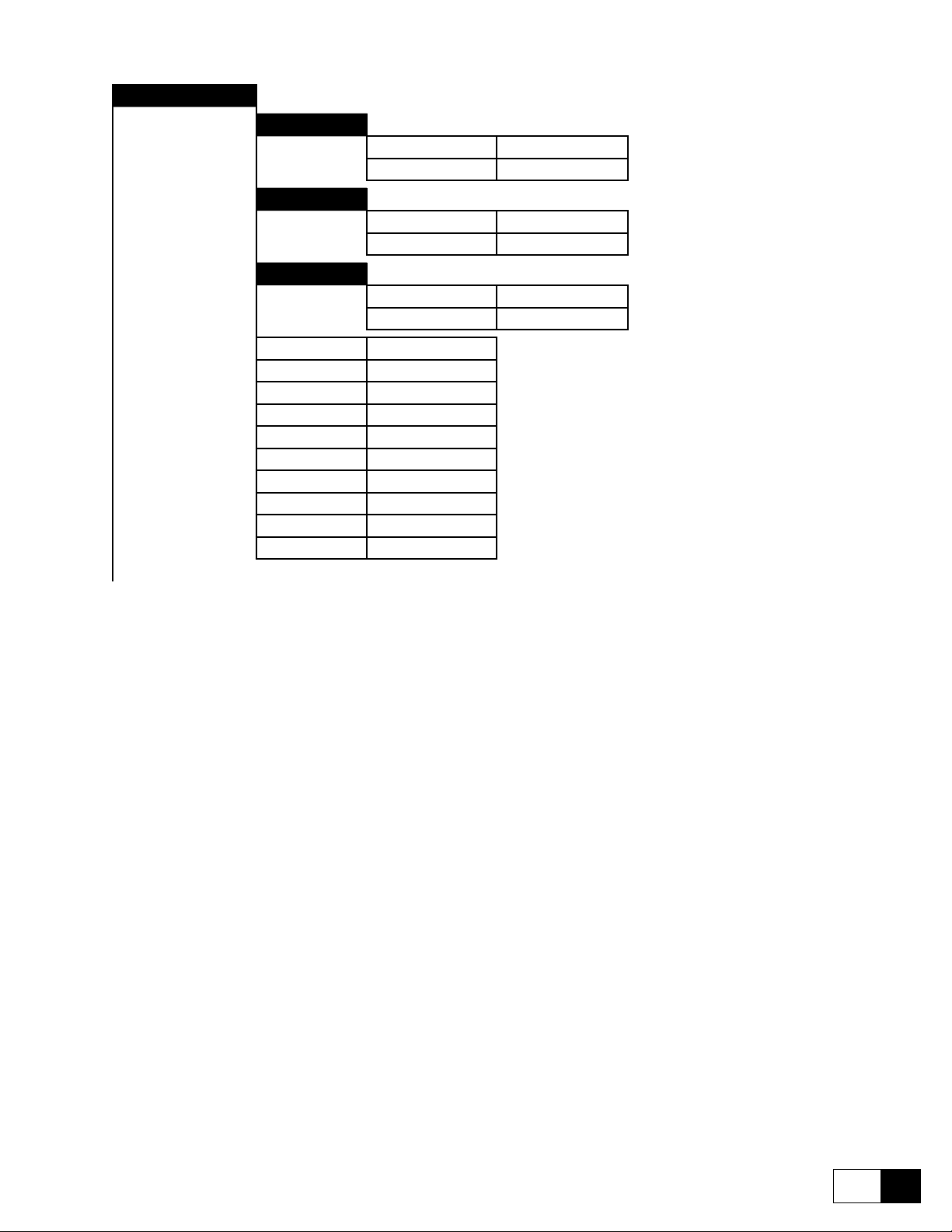
RAMP
DV-300 Adjustable Speed Drives
Acceleration
[21] Acc delta speed [FF]
[22] Acc delta time [s]
Deceleration
[29] Dec delta speed [FF]
[30] Dec delta time [s]
Quick stop
[37] QStp delta speed [FF]
[38] QStp delta time [s]
[18] Ramp shape
[19] S shape t const [ms]
[663] S acc t const [ms]
[664] S dec t const [ms]
[20] Ramp +/- delay [ms]
[673] Fwd-Rev
[245] Enable ramp
[344] Ramp out = 0
[345] Ramp in = 0
[373] Freeze ramp
——— CONVERTER OPERATION ———
17
5
Page 94

SPEED REGULAT
GEI-100332Ga
[118] Speed ref [rpm]
[236] Speed reg output [% ]
[322] Lock speed reg
[242] Enable spd reg
[348] Lock speed I
[1016] Aux spd fun sel
[444] Prop lter [ms]
Self tuning
[1029] Fwd-Rev spd tune
[1048] Test T curr lim [%]
[1027] Start
[1014] Inertia [kg*m*m*]
[1030] Inertia Nw [kg*m*m*]
[1015] Friction [N*m]
[1031] Friction Nw [N*m]
[87] Speed P [%]
[1032] Speed P Nw [%]
[88] Speed I [%]
[1033] Speed I Nw [%]
[1028] Take val
Spd zero logic
Speed up
Droop function
Inertia/loss cp
[123] Enable spd=0 I
[124] Enable spd=0 R
[125] Enable spd=0 P
[126] Spd=0 P gain [%]
[106] Ref 0 level [FF]
[445] Speed up gain [%]
[446] Speed up base [ms]
[447] Speed up lter [ms]
[696] Droop gain [%]
[697] Droop lter [ms]
[698] Load comp [%]
[700] Droop limit [FF]
[699] Enable droop
[1014] Inertia [kg*m*m]
[1015] Friction [N*m]
[1013] Torque const [N*m/A]
[1012] Inertia c lter [ms]
18
5
——— CONVERTER OPERATION ———
Page 95

CURRENT REGULAT
FLUX REGULATION
DV-300 Adjustable Speed Drives
[41] T current ref [%]
[199] Motor current [%]
[1430] Mot cur threshld [%]
[1431] Mot cur th delay [ms]
[453] Arm resistance [ ]
[454] Arm inductance [mH]
[587] E int [V]
[452] R&L Search
[353] Zero torque
[497] Enable ux reg
[469] Flux reg mode
[498] Enable ux weak
[499] Speed-0 f weak
[500] Flux reference [%]
[234] Flux current %
[921] Out vlt level
Flux \ if curve
[916] I eld cnst 40
[917] I eld cnst 70
[918] I eld cnst 90
[919] Set ux / if
[920] Reset ux / if
[374] Nom ux curr [A]
[280] Motor nom ux [A]
——— CONVERTER OPERATION ———
19
5
Page 96

REG PARAMETERS
Percent values
Base values
GEI-100332Ga
Speed regulator
Flux regulator
Voltage reg
Speed regulator
[87] Speed P [%]
[88] Speed I [%]
[459] Speed P bypass [%]
[460] Speed I bypass [%]
[91] Flux P [%]
[92] Flux I [%]
[493] Voltage P [%]
[494] Voltage I [%]
[93]
[94]
Speed P base [A/rpm]
Speed I base [A/rpm·ms]
In use values
Flux regulator
[97] Flux P base
[98] Flux I base
Voltage reg
[495]
[496]
[99] Speed P in use [%]
[100] Speed I in use [%]
Voltage P base [f%/V]
Voltage I base [f%/V·ms]
20
5
——— CONVERTER OPERATION ———
Page 97

CONFIGURATION
DV-300 Adjustable Speed Drives
[252] Main commands
[253] Control mode
[45] Speed base value [FF]
[179] Full load curr [A]
[175] Max out voltage [V]
[412] Ok relay funct
Speed fbk
[162]
[414] Speed fbk sel
[457] Enable fbk contr
[458] Enable fbk bypas
[456] Flux weak speed [%]
[455] Speed fbk error [%]
[562] Tacho scale
[563] Speed offset
[416] Encoder 1 pulses
[169] Encoder 2 pulses
[649] Refresh enc 1
[652] Refresh enc 2
[911] Enable ind store
Motor max speed [rpm]
Drive type
Dimension fact
Face value fact
Prog alarms
[465] Drive size [A]
[201] 2B + E
[464] Size selection
[331] Software version
[50] Dim factor num
[51] Dim factor den
[52] Dim factor text
[54] Face value num
[53] Face value den
Failure supply
[194] Latch
[195] Ok relay open
Undervoltage
[481] Undervolt thr [V]
[357] Latch
[358] Ok relay open
[470] Hold off time [ms]
[359] Restart time [ms]
——— CONVERTER OPERATION ———
21
5
Page 98

GEI-100332Ga
Overvoltage
Overspeed
Heatsink
Overtemp motor
[203] Activity
[361] Latch
[362] Ok relay open
[482] Hold off time [ms]
[483] Restart time [ms]
[1426] Overspeed thr [rpm]
[1422] Activity
[1421] Latch
[1423] Ok relay open
[1424] Hold off time [ms]
[1425] Restart time [ms]
[368] Activity
[370] Ok relay open
[365] Activity
[367] Ok relay open
External fault
Brake fault
Motor I2t ovrld
Drive I2t ovrld
Overcurrent
[354] Activity
[355] Latch
[356] Ok relay open
[502] Hold off time [ms]
[501] Restart time [ms]
[1296] Activity
[1297] Ok relay open
[1419] Activity
[1442] Latch
[1420] Ok relay open
[1441] Ok relay open
[584] Overcurrent thr [%]
[212] Activity
[363] Latch
[364] Ok relay open
[586] Hold off time [ms]
[585] Restart time [ms]
22
5
——— CONVERTER OPERATION ———
Page 99

DV-300 Adjustable Speed Drives
Field loss
[473] Activity
[471] Latch
[472] Ok relay open
[475] Hold off time [ms]
[474] Restart time [ms]
Delta frequency
[1437] Delta freq thres [%]
[1432] Activity
[1433] Latch
[1434] Ok relay open
[1435] Hold off time [ms]
[1436] Restart time [ms]
Speed fbk loss
[478] Activity
[477] Ok relay open
[480] Hold off time [ms]
Set serial comm
Opt2 failure
[639] Activity
[640] Ok relay open
Bus loss
[634] Activity
[633] Latch
[635] Ok relay open
[636] Hold off time [ms]
[637] Restart time [ms]
Hw opt1 failure
[386] Activity
[387] Ok relay open
Enable seq err
[728] Activity
[729] Latch
[730] Ok relay open
[319] Device address
[408] Ser answer delay
[323] Ser protocol sel
[326] Ser baudrate sel
[85] Pword 1
——— CONVERTER OPERATION ———
23
5
Page 100

I/O CONFIG
GEI-100332Ga
Analog outputs
Analog output 1
[66] Select output 1
[62] Scale output 1
Analog output 2
[67] Select output 2
[63] Scale output 2
Analog output 3
[68] Select output 3
[64] Scale output 3
Analog output 4
[69] Select output 4
[65] Scale output 4
Analog inputs
Analog input 1
[70] Select input 1
[295] An in 1 target
[71] Input 1 type
[389] Input 1 sign
[72] Scale input 1
[73] Tune value inp 1
[259] Auto tune inp 1
[792] Input 1 lter [ms]
[1042] Input 1 compare
[1043] Input 1 cp error
[1044] Input 1 cp delay
[74] Offset input 1
Analog input 2
[75] Select input 2
[296] An in 2 target
[76] Input 2 type
[390] Input 2 sign
[77] Scale input 2
[78] Tune value inp 2
[260] Auto tune inp 2
[79] Offset input 2
Analog input 3
[80] Select input 3
[297] An in 3 target
[81] Input 3 type
[391] Input 3 sign
[82] Scale input 3
[83] Tune value inp 3
[261] Auto tune inp 3
[84] Offset input 3
24
5
——— CONVERTER OPERATION ———
 Loading...