

Page 1
TM
Page 2

This book is referred to SW version 9.2X00.
This book replaces the Instruction Book GEH-6129 Rev. 7.1
These instructions do not purport to cover all details or variations in equipment, nor to provide every possible contingency
to be met during installation, operation, and maintenance. If further information is desired or if particular problems
arise that are not covered sufficiently for the purchaser’s purpose, the matter should be referred to GE Consumer &
Industrial.
This document contains proprietary information of General Electric Company, USA and is furnished to its customer
solely to assist that customer in the installation, testing, operation, and/or maintenance of the equipment described.
This document shall not be reproduced in whole or in part nor shall its contents be disclosed to any third party without
the written approval of GE Consumer & Industrial..
© 2008 by General Electric Company, USA. All rights reserved.
Page 3

Table of Contents
1. PRECAUTIONS AND WARNINGS ........................................................................................5
2. PREFACE...............................................................................................................................7
2a. Important Introduction.................................................................................................................................... 7
2b. Drive Memory ................................................................................................................................................ 7
2c. Basic control wiring and starting .......................................................................................... .......................... 7
2d. GE Control System toolbox VS keypad setup............................................................................................... 8
3. PRE POWER CHECKS.......................................................................................................... 9
3a. Grounds/grounding........................................................................................................................................ 9
Regulator board terminals ................................................................................................................................... 9
3b. Meggering...................................................................................................................................................... 9
3c. Connections ................................................................................................................................................... 9
3d. motor data tabulation................................................................................................................................... 10
Nameplate dual speed rating............................................................................................................................. 10
3e. field current calibration dipswitch S14 ..........................................................................................................11
3f. Regulation card jumper settings ................................................................................................................... 13
4. POWER UP CHECKS AND INITIAL CONFIGURING ......................................................... 14
4a. Don’t turn on power yet.....check power input ............................................................................................. 14
4b. Power up..................................................................................................................................................... 14
4c. Loading default settings............................................................................................................................... 14
5. INITIAL PARAMETER SETUP............................................................................................. 15
6. CURRENT REGULATOR SELF TUNE................................................................................ 18
7. CHECK MOTOR/ROLL ROTATION, SPEED FEEDBACK POLARITY, AND
CALIBRATIONS................................................................................................................... 19
7a. Check motor/roll rotation.............................................................................................................................. 19
7b. Calibrations.................................................................................................................................................. 19
7c. Checking current regulator performance using parameter Eint................................................................... 19
8. SETUP SPEED FEEDBACK................................................................................................ 20
8a. Check speed feedback polarity ................................................................................................................... 20
8b. Setup ENC 2 for digital encoder for speed feedback ................................................................................. 20
8c. ENC 1 for digital encoder for speed feedback............................................................................................. 21
8d. Analog tachometer....................................................................................................................................... 21
8e. Save setup................................................................................................................................................... 22
9.CONFIGURE ADDITIONAL MOTOR FIELD PARAMETERS ............................................... 23
9a. Configure field weakening operation ........................................................................................................... 23
9b. hints on Flux regulator stability .................................................................................................................... 23
Page 4

10. SPEED SELF TUNE........................................................................................................... 24
11. SAVE PARAMETERS TO RETAIN IN PERMANENT MEMORY....................................... 24
12. OTHER COMMON SETUP PARAMETERS....................................................................... 25
12a. Terminal board input control VS keypad .................................................................................... ................ 25
12b. Configurable I/O.......................................................................................................... ............................... 25
12c. Configure jog operation.............................................................................................................................. 26
13. INTERNAL REPLACEMENT FUSES ................................................................................. 27
14. BASIC OPERATING DESCRIPTIONS...............................................................................28
14 a. standard inputs functional description ...................................................................................................... 28
14b. Regulation card LEDs................................................................................................................................ 28
14c. Keypad programmer LED description........................................................................................................ 28
14 d. Keypad menu structure............................................................................................................................. 29
15. QUICK TROUBLESHOOTING........................................................................................... 30
15a. Regulation card testpoints ......................................................................................................................... 30
15b. Failure messages and troubleshooting hints............................................................................................. 30
Page 5

DV-300 Adjustable Speed Drives
1. PRECAUTIONS AND WARNINGS
According to the EEC standards the DV300 and
accessories must be used only after checking that the
machine has been produced using those safety devices
required by the 89/392/EEC set of rules, as far as the
machine industry is concerned.
Drive systems cause mechanical motion. It is the responsibility of the user to insure that any such motion
does not result in an unsafe condition. Factory provided
interlocks and operating limits should not be bypassed
or modified.
WARNING - ELECTRICAL SHOCK AND BURN
HAZARD:
When using instruments such as oscilloscopes to work
on live equipment, the oscilloscope’s chassis should
be grounded and a differential amplifier input should
be used. Care should be used in the selection of probes
and leads and in the adjustment of the oscilloscope so
that accurate readings may be made. See instrument
manufacturer’s instruction book for proper operation
and adjustments to the instrument.
WARNING - FIRE AND EXPLOSION HAZARD:
Fires or explosions might result from mounting drives
in hazardous areas such as locations where flammable
or combustible vapors or dusts are present. Drives
should be installed away from hazardous areas, even if
used with motors suitable for use in these locations.
Improper installation of motors or drives may therefore
cause the failure of the device as well as serious injury
to persons or material damage.
Follow the instructions given in this manual and observe
the local and national safety regulations applicable.
CAUTION:
Do not connect power supply voltage that exceeds the
standard specification voltage fluctuation permissible.
If excessive voltage is applied to the Drive, damage to
the internal components will result.
CAUTION:
Do not operate the drive without the ground wire
connected. The motor chassis should be grounded to
earth through a ground lead separate from all other
equipment ground leads to prevent noise coupling.
The grounding connector shall be sized in accordance
with the NEC or Canadian Electrical Code. The
connection shall be made by a UL listed or CSA certified
closed-loop terminal connector sized for the wire gauge
involved. The connector is to be fixed using the crimp
tool specified by the connector manufacturer.
CAUTION:
Do not perform a megger test between the Drive
terminals or on the control circuit terminals.
WARNING - STRAIN HAZARD:
Improper lifting practices can cause serious or fatal
injury . Lift only with adequate equipment and trained
personnel.
WARNING:
Replace all covers before applying power to the drive.
Failure to do so may result in death or serious injury.
WARNING:
Adjustable speed drives are electrical apparatus for use
in industrial installations. Parts of the drives are
energized during operation. The electrical installation
and the opening of the device should therefore only be
carried out by qualified personnel.
—————— Quick Start up guide ——————
CAUTION:
Because the ambient temperature greatly affects drive
life and reliability, do not install the drive in any location
that exceeds the allowable temperature. Leave the
ventilation cover attached for temperatures of 40° C
(104° F) or below.
CAUTION:
If the drive’s Fault Alarm is activated, consult the
TROUBLESHOOTING section of the instruction book,
and after correcting the problem, resume operation. It
is not recommended to reset the alarm automatically
by external sequence, etc.
5
QS
Page 6

GEH-6129
CAUTION:
Be sure to remove the desicant dryer packet(s) when
unpacking the Drive. (If not removed these packets may
become lodged in the fan or air passages and cause the
Drive to overheat).
CAUTION:
The Drive must be mounted on a wall that is constructed
of heat resistant material. While the drive is operating,
the temperature of the Drive’s cooling fins can rise to a
temperature of 90° C (194°F).
NOTE! The terms “converter”, “controller” and
“drive” are sometimes used interchangably
throughout the industry. W e will use the term
“drive” in this document
NOTE! 1. Never open the device or covers while the
AC input power supply is switched on.
Minimum time to wait before working on the
terminals or inside the device is listed in the
instruction book
2. Do not touch or damage any components
when handling the device. The changing of
the isolation gaps or the removing of the
isolation and covers is not permissible. If the
front plate has to be removed because of a
room temperature higher than 40 degrees, the
user has to ensure that no accidental contact
with live parts may occur.
3. Protect the device from extreme
environmental conditions (temperature,
humidity, shock etc.)
4. No external voltage should be connected
to the output of the converter (terminals C &
D).
5. When engaging a running motor, the Auto
capture function (Auto capture in the ADD
SPEED FUNCT menu) must be activated.
6. Only an standard inductive DC motor load
should be connected to the output of the drive
(terminals C & D).
7. Always connect the Drive to the protective
ground (PE) via the marked connection
terminals (PE2) and the housing (PE1). The
discharge current to earth may be greater than
3.5 mA. A fixed (non disconnectable) ground
connection must be provided for this, to
comply with EN 50178 (VDE 0160). It is
aso recommended that the ground cable
should have a cross section of at least 10 mm
8. The electrical commissioning should only
be carried out by qualified personnel, who
are also responsible for the provision of a
suitable ground connection and a cable
protection for the power supply in accordance
with the local and national regulations. The
motor must be protected against overloads.
9. No dielectric tests using meggers or hi pots
should be carried out on the drive. A suitable
measuring instrument (internal resistance of
at least 10 kΩ/V) should be used for
measuring the signal voltages.
10.It is recommended to disconnect the drive
from the AC input feeder to prevent
unintentional running in the event of a failure,
even if the drive is disabled.
NOTE! The DV-300 operates from the inputs: start
and enable. If the enable input / signal is
removed, the start signal is not automatically
removed. Re establishing the enable signal
with the start signal already present can cause
motor rotation.
This guide highlights simplified steps to
program and tr oubleshoot the DV -300 drive.
In is intended to be used as a aid for trained
personnel, and to complement the DV-300
Instruction Book, after the drive is installed
in accordance with the DV-300 Instruction
Book.
2
.
QS
6
—————— Quick Start up guide ——————
Page 7
2. PREFACE
DV-300 Adjustable Speed Drives
2a. Important Introduction
This startup guide is based on starting up the DV-300
out of the box from the factory , based on factory default
settings.
This guide will walk the user through sequential steps
and checkpoints for startup. It is recommended to follow
this guide sequentially without skipping steps unless
this guide instructs the user to do so.
Parameter menus and names will be shown in a keypad
screen symbol, for example:
SPEC FUNCTIONS
Save parameters
parameter names will also be shown in brackets [save
parameters]
2b. Drive Memory
There are two memories for drive parameters. One is
the active memory which is always the one currently
in use by the drive. The other is the permanent memory
which is the drive accesses on power up. This is the
ONL Y time when the drive looks at permanent memory .
All file uploads and downloads, all changes, etc. are
made only to the active memory and read from the active
memory. The only time permanent memory is used in
any way is that when it is booted into active memory
on power up, and when it is stored using the “Save
Parameters” command.
When parameters are changed during set up, the
changes are not permanent. The parameters changes
are temporarily used, but unless [SAVE
P ARAMETERS] is executed, after recycling power, the
changes are lost. This is an advantage to “experiment”
with a parameter change to see how the change works,
and not modify the permanent set-up.
As parameters are entered it is recommended to
occasionally save entered data. The [SAVE
PARAMETER]command is located at the end of the
START UP, TUNING, and under the SPEC
FUNCTIONS menu.
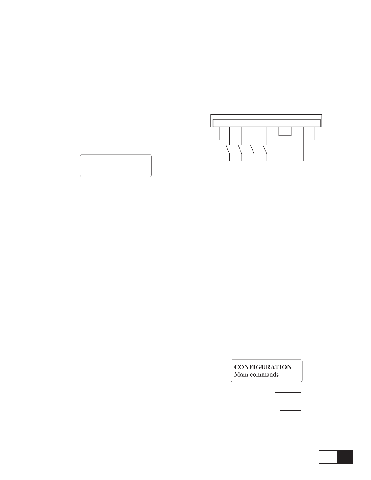
2c. Basic control wiring and starting
The terminal board inputs provide the user a hardwired
control means to sequence the drive.
For testing, the inputs can be wired using a local switch
box per the drawing below.
The actual control interface can be used if it has been
checked out, and is a convenient and reliable control
means.
11 12 13 14 15 16 18 19 20
11 - power supply common
12 - enable (close to activate)
13 - start (close to activate)
14 - fast stop (open to activate)
15 - external fault (open to activate)
16 - common for TB pts 11 -15
18 - + 24 V common
19 - + 24 VDC
20 - ground
After the control circuits are wired, and proven to
operate, repower the DV-300.
Close only the switch for EXTERNAL FAULT input.
Reset external drive fault with the keypad’s CANC key .
The default DV-300 configuration sets the control
inputs in a “digital” mode, which is for keypad and
PC control. In this mode, the terminal board inputs
must be connected to 24 VDC as well as commanded
from the keypad or PC.
This mode is set by parameter:
When this parameter is set to terminals, the terminal
board inputs control the drive.
When this parameter is set to
digital, the keypad,
PC, or bus controls the sequencing, but opening the
terminal board input will also cause the signal to
drop out.
—————— Quick Start up guide ——————
7
QS
Page 8
GEH-6129
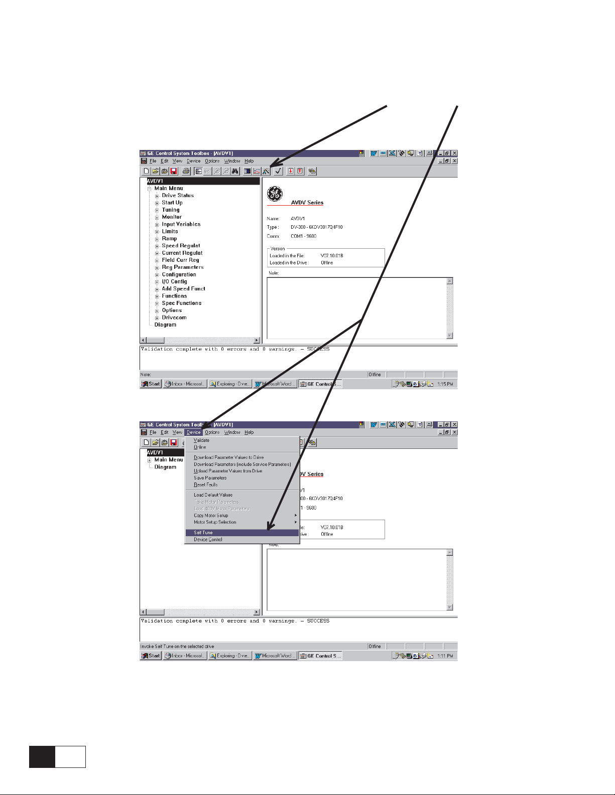
2d. GE Control System toolbox VS keypad setup
After following the suggestions for startup using Hints, pre power checks , and power up checks, a user
configuring the drive with the GE Control System toolbox can follow the wizards and self tune menus
to complete the setup.
QS
8
—————— Quick Start up guide ——————
Page 9
3. PRE POWER CHECKS
3a. Grounds/grounding
DV-300 Adjustable Speed Drives
Verify an AC power ground wire exists from the incoming power / isolation transformer to the DV-300
input ground terminal.
Verify the ground lead of the DV-300 output terminal is
wired to the motor, or the motor is properly grounded.The
DV-300 power supply, terminal point 11, may be
referenced to ground through a different ground circuit,
or may be wired to the same ground by connecting terminal
point 11 to terminal point 10 or 20.
V erify the AC input leads, DC output armature and field
leads, and control wiring to and from the drive terminals
are not grounded.
Use a digital voltmeter or equivalent to take these
readings if the wiring is attached to the drive. Remember
that the 0V terminal may be intentionally grounded.
Isolated field wiring generally reads at least 2-3 MW
to ground.
3b. Meggering
Cabling must be disconnected or isolated from the DV 300 drive when meggered or hi potted. Drive damage
could result if this advice is not followed.
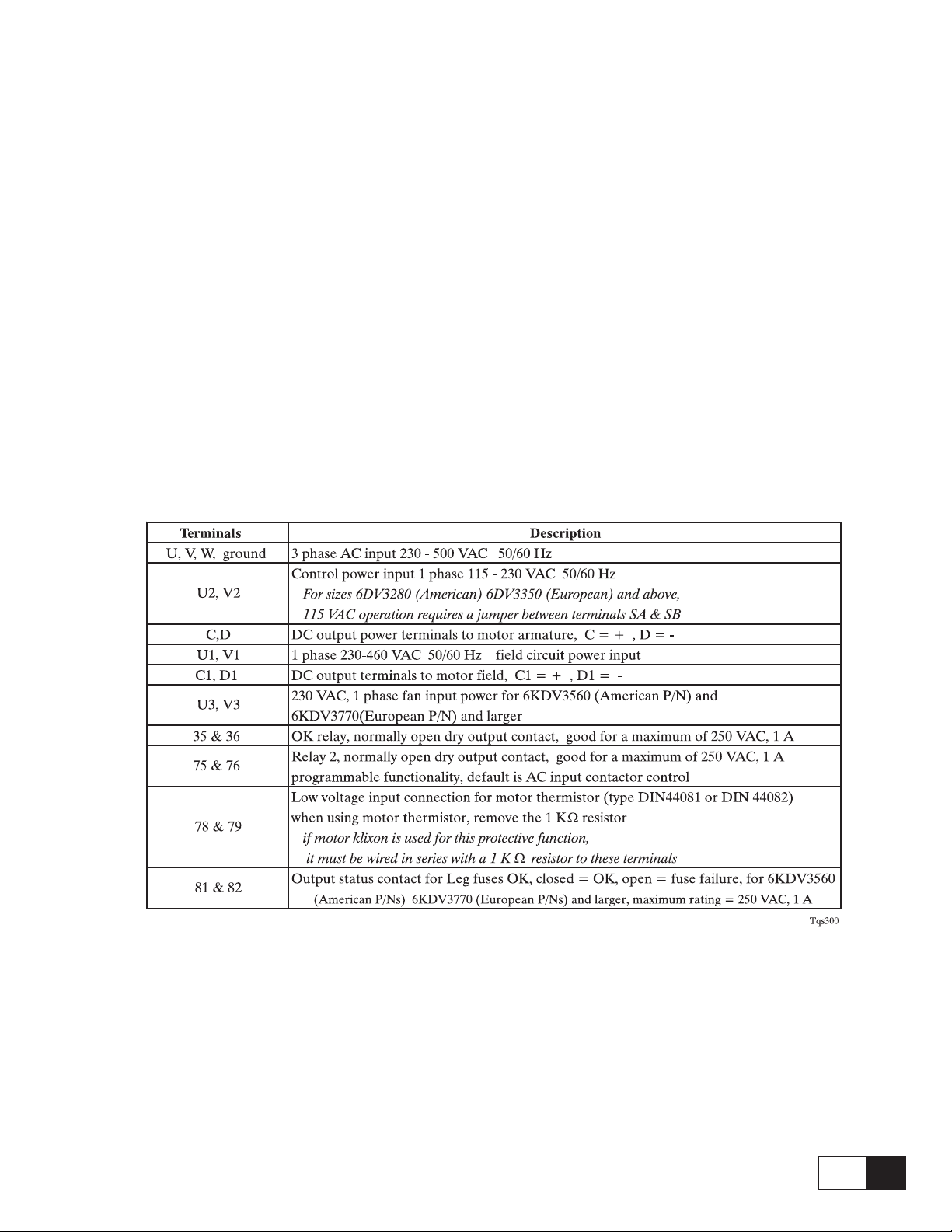
3c. Connections
Without applying power , double check all connections
and wire terminals to make sure they are tight.
V erify each connection is wired per wiring diagrams,
and are appropriate for the current and voltage
levels specified.
Regulator board terminals
1,2 = programmable analog input 1,
3,4 = programmable analog input 2,
5,6 = programmable analog input 3
7 = + 10 V , 8 = -10V, 9 = +/- 10 V supply common ,
10 = ground,
11 = common
12 = enable input, 13 = start input,
14 = fast stop input, 15 = external fault input,
16 = common point for terminals 12 through 15,
—————— Quick Start up guide ——————
17 = no connection,
18 = common for the 24V power supply,
19 = + 24 VDC output, 20 = ground
XE1 ( ENC1) 9 pin sinusoidal encoder input
XE2 ( ENC2) 9 pin incremental encoder input
DC tach input: - , + terminals for DC tach. max volts ≤ 108 no jumper,
108 ≤ max volts ≤ 188 VDC jumper B & C
188 ≤ max volts ≤ 340 VDC jumper A & C
20 = Screen connection (PE) (connected w/housing)
9
QS
Page 10

GEH-6129
3d. motor data tabulation
Before commissioning, it is recommended to record the actual motor nameplate data. Also record gearbox, and
attached roll diameter, or any appropriate mechanical data that may be needed during setup.
This table may be used as a guide to record motor nameplate and application data
Typical DC Motor Nameplate
HP (kW) RPM Volts
Arm Amps
Fld Amps Fld ohms 25 C
Fld is an abbreviation for field
Gear in speed
· gear in speed is the top motor rpm to achieve rated machine speed
Acceleration time · : seconds
Deceleration time
Field control
(circle one)
tachometer type
and calibration
(circle one)
· : seconds
: constant current, (fixed field current)
field weakening (see example below)
: analog V / RPM
digital tacho into Encoder 2 PR
see jumpers note in 3.f.
None
· : rpm
P
see jumpers in 3.f.
see jumpers in 3.f.
Nameplate dual speed rating
The value for RPM may be represented with two values, the first representing base speed , which is the rpm at
nameplate volts and nameplate field current.
A second RPM value, if shown, corresponds to rated top speed, which is achieved at rated nameplate volts, and
a weak field setting. The weak field setting would correspond to the second value of field amps.
For the nameplate below, base speed is 1750 rpm @ 3 amps field and top speed is 2300 rpm @ 1 amp field
Typical DC Motor Nameplate
HP (kW) 20 RPM 1750 / 2300 Volts 500
Arm Amps 32
Fld Amps 3.0 / 1.0 Fld ohms 25 C 72
Verify the motor data matches the drive power rating, output voltages, and required motor speed is achievable.
If files in the GE Control System Toolbox were predefined off-line, verify the entered data is correct before
downloading to the drive
QS
10
—————— Quick Start up guide ——————
Page 11

DV-300 Adjustable Speed Drives
3e. field current calibration dipswitch S14
The DV-300 regulation card is shipped with the field current feedback resistor dipswitches calibrated for the
maximum rating of the field package capacity for each size DV-300.This maximum field package rating is
incorporated in the DV- 300 catalog number.
For example: 6KDV3017Q4F
Compare the actual motor field data, recorded in step 3d., to the maximum rating of the field package
of the DV-300 model supplied (in the instruction book) , and to the field calibration dipswitch S14, as shown
below Table 3e1, 3e2, 3e3.
· For fixed field current operation, if the actual motor (base) field current = 10% of the maximum rating of the
field package it is required to calibrate the field current feedback scaling using dipswitch S14.
· For weak field operation, also referred to CEMF field control or crossover field control, if the actual top
speed motor field current = 10% of the maximum rating of the field package it is required to calibrate the
field current feedback scaling using dipswitch S14.
Calibration to the exact field current setting is not required, as long as the above conditions are met.
Calibration is not required if the field control is provided from a source other than the DV-300.
10D1 The 10 represents a 10 A field exciter.
Example:
For the nameplate below , base speed is 1750 rpm @ 2.9 amps field and top speed is 2300 rpm @ 2.1 amp field.
The motor is desired to run at 2300 rpm, so the minimum field is 1 amp.
Typical DC Motor Nameplate
HP (kW) 20 RPM 1750 / 3000 Volts 500
Arm Amps 32
Fld Amps 2.9 / .9 Fld ohms 25 C 72
For DV-300, 6KDV3035..., the field package is rated for 10 A. The motor is needed to run at 3000 rpm, so
requires a minimum field setting of .9 amps. .9 A is less than 10% of the 10 A default dipwitch setting therefore
it needs changed.
A good setting for field curr scaling is 3.0 amps, S14-5 = ON, all others = Off.
The parameter [field curr scaling] also needs set for 3.0 amps.
RECORD REQUIRED S14 DIPSWITCH SETTING and FIELD SCALING AMPS
from the tables on the next page
Field curr scale S14 -1 S14 -2 S14-3 S14-4 S14-5 S14-6
—————— Quick Start up guide ——————
Tqs310
11
QS
Page 12

GEH-6129
Table 3e1: DV-300 Rev 7.1 or greater, field current calibration resistor dipswitch settings for
model numbers 6KDV3017...-3850, (European model numbers 6KDV3020..-310H)
Resistance = 1667 / field current amps
Switch ohms 168.5 ohm 333 ohm 182 ohm 36.4 ohm 845 ohm 1668 ohm
Field curr scale S14-1 S14-2 S14-3 S14-4 S14-5 S14-6 S14-7 S14-8
1.0 A OFF OFF OFF OFF OFF ON 1685 ohm
2.0 A OFF OFF OFF OFF ON OFF 845 ohm
3.0 A OFF OFF OFF OFF ON ON 558.8 ohm
5.0 A OFF ON OFF OFF OFF OFF 333 ohm
10.0 A ON OFF OFF OFF OFF OFF 168.5 ohm
12.9 A ON OFF OFF OFF ON ON 129.2 ohm
17.2 A OFF ON ON OFF ON ON 97 ohm
20.0 A ON OFF ON OFF OFF ON 83 ohm
24.1 A ON ON ON OFF OFF OFF 69 ohm
Not used
1=dipswitch in ON position
Table 3e2: DV-300 Rev 7.1 or greater, field current calibration resistor dipswitch settings for
model numbers 6KDV30900...-31500, (European model numbers 6KDV31200..-32000)
Resistance = 3332 / field current amps
Field current scale S14-1 S14-2 S14-3 S14-4 S14-5 S14-6 Equivalent resistance
40A ON OFF ON OFF OFF OFF 83
20A ON OFF OFF OFF OFF OFF 168
10A OFF ON OFF OFF OFF OFF 332
W
W
W
Equivalent
resistance
DV0032g
1=dipswitch in ON position
Tqs330
Table 3e3 : DV-300 Rev 7.1 or greater, field current calibration resistor dipswitch settings for
model numbers 6KDV31800...-32350, (European model numbers 6KDV32400..-33300)
Resistance = 1667 / field current amps
Field current scale S14-1 S14-2 S14-3 S14-4 S14-5 S14-6 Equivalent resistance
70A ON OFF ON ON OFF OFF 23.8
46A OFF OFF OFF ON OFF OFF 36.4
24A ON ON ON OFF OFF OFF 69.2
14A OFF ON ON OFF OFF OFF 117.6
1=dipswitch in ON position
W
W
W
W
Tqs340
Setting all dipswitch settings to 0 (OFF) allows a custom calculated resistor to be used in terminals LA and LB,
on the regulation board, using the formulas listed above.
QS
12
—————— Quick Start up guide ——————
Page 13

DV-300 Adjustable Speed Drives
3f. Regulation card jumper settings
Jumper settings to use 6KCV300PIU PC Interface Unit - ( RS232 isolator )
Jumpers S18 & S19 = B, Jumper S29 & S30 = ON Jumper S15 = Off
or the 6KCV300CTI PC configurator Interface Unit - ( RS232/RS485 )
Jumpers S18 & S19 = B, Jumper S29 & S30 = On Jumper S15 = On
Jumper Factory Description Record
default settings:
S4 Matching of the input voltage of the tachogenerator reaction, see table 4.4.3 (User manual)
Speed feedback channel selection
A = Enc 1 speed feedback channel
S5,S6 B
B = analog tachometer
Analog input 1 setup
S9 Off
S10 Off
S11 Off
S12,S13 Off
S15 On Adaptation of the regulation card to the device type, see table 4.4.2 (User manual)
S18,S19 B
S20 Off
S21,S22,
S23
ON Mounted Jumpers
OFF Non mounted Jumpers
Off = 0-10 V/ -10 V to + 10 V input
ON = 4-20mA/0-20mA input
Analog input 2 setup
Off = 0-10 V/ -10 V to + 10 V input
ON = 4-20mA/0-20mA input
Analog input 3 setup
Off = 0-10 V/ -10 V to + 10 V input
ON = 4-20mA/0-20mA input
RS 485 programming port (XS) termination resistors
Off - no termination resistors
ON - termination resistors in
Selection of the internal/external supply of the RS485 serial interface
OFF - Serial interface supplied from the outside (PIN 5 and 9) and galvanic divided form the
regulation section.
ON - Serial interface supplied from the inside and connected to the potential reference point of the
regulation. PIN 5 and 9 are used to supply the adaptor of the serial interface (for use of
6KDV300PIU).
Encoder 2 input (XE2) marker channel ( also called index , or C channel) input
Off - marker channel (also called index , or C channel) input not used
ON - marker channel (also called index , or C channel) input monitored
Encoder 2 input (XE2) A, /A, B, /B voltage
Off
Off - 15 ... 30 V
ON - 5 V
( XE1 connector with sinusoidal encoder, or digital encoder with 6KCV300DES )
for digital encoder into XE2, or armature feedback (tachless) this jumper position has no effect
Tqs350
NOTE! For sizes 6KDV3280... (American P/N) 6KDV3350... (European P/N) and higher, 1 15 VAC operation
requires a jumper between terminals SA & SB. These points are located on a terminal board on the top
of the converter module.
—————— Quick Start up guide ——————
13
QS
Page 14

4. POWER UP CHECKS AND INITIAL CONFIGURING
4a. Don’t turn on power yet.....check power
input
GEH-6129
To load factory default settings, go to:
Make sure the AC incoming voltage at the input side of
the disconnect switch(s) is/are correct for the main
converter, field control (460 VAC max), and control
power (115 - 230 VAC).
Disconnect drive connectors from option cards DGF
and SBI ( LAN interface cards ) if supplied.
This will keep other potential sources of control and
referencing from interfering with the initial setup.
To make absolutely sure motor motion is not possible
from any source on initial power up, pull out the I/O
connectors for Regulator terminal board points 1 - 20.
If the DV-300 is much larger than the actual motor
rating, the default field current setting may be higher
than the actual motor field. T o prevent overloading and
heating of the motor field circuit in this situation, it
may be advisable to disconnect the field circuit
connector (with the wiring attached) until the calibrated
data is entered.
4b. Power up
If possible, turn control power on separately first, check
that everything looks OK visually.
If one single disconnect switch is provided , turn on
power at this time.
The keypad LED should show “external fault” if the
terminal board connector points 11-20 are pulled out.
If other faults are present, ignore them for now.
SPEC FUNCTIONS
Load default
to permanently save the default settings, press the up
arrow to
SPEC FUNCTIONS
Save parameters
Press CANC, then hold down the up arr ow to return to
the top of the main menus.
Press ENT
Press ENT
DEFAULT NOTE:
Regulation card Dipswitch S15 sets the
converter size and type, and is set properly
from the factory.
In the event of card replacement, the
dipswitch may need changed. Refer to the
DV-300 Instruction book for the dipswitch
table.
Dipswitch S15 - 7 = off; identifies to the DV 300 firmware: 400 V European defaults
Dipswitch S15 - 7 = on; identifies to the DV 300: 460 V American defaults.
4c. Loading default settings
The DV-300 contains appropriate default settings for
typical 500 VDC GE motors, right out of the box.
If the drive has been powered before by persons
unknown, or the exact programming condition of the
drive is unknown, or for just getting a fresh
configuration start, executing a “load default”
parameters may be in order.
If the drive has been supplied from a third party as an
engineered package, many of the settings may be
already set, so loading default may be inappropriate.
QS
14
—————— Quick Start up guide ——————
Page 15

DV-300 Adjustable Speed Drives
START UP
Acc delta time
START UP
Dec delta speed
START UP
Dec delta time
START UP
Motor data
Motor data
Motor nom flux
Motor data
Flux reg mode
5. INITIAL PARAMETER SETUP
This part of the procedure sets up the DV-300 for
CEMF feedback (open loop) with constant field
current.
The enable input and start input ( TB 12 and 13)
should be open circuit, i.e. not tied to 24 VDC.
GE DRIVE DV-300
DRIVE STATUS
Using the keypad, press the down arrow to go to the
START UP menu .
GE DRIVE DV-300
START UP
START UP
Speed base value
Press ENT
Press ENT
Enter the same rpm as entered for Speed base value
( rated machine motor rpm recorded from section
3 d., corresponding to the maximum desired motor
rpm ), press ENT
Press the down arrow to go to the next parameter.
Press ENT
Enter the desired acceleration time in seconds as
recorded in section 3d., press enter
Press the down arrow to go to the next parameter.
Press ENT
Enter the same rpm as entered for speed base value(
rated motor rpm recorded from section 3 d.,
corresponding to the maximum desired motor rpm
), press enter
Enter the rated motor rpm recorded fr om section 3
d., ”gear in speed” corresponding to the maximum
desired motor rpm., press ENT
This parameter sets the value of speed reference that is
used as 100%, 1 per unit, in other words, the “base
value”.
Press the down arrow to go to the next parameter
START UP
Field curr scale
Enter the field current scale amps corresponding to
the S14 dipswitch setting recorded from section 3
e., press ENT
Press the down arrow to go to the next parameter.
START UP
Speed base value
Press ENT
Default = on,
Press the down arrow to go to the next parameter.
Press ENT
Enter the desired acceleration time in seconds as
recorded in section 3d., press enter
Press the down arr ow to go to the next parameter menu.
Press ENT
Press ENT
Enter the nameplate base field current amps as
recorded in section 3d, press ENT
Press the down arrow to go to the next parameter.
Press the down arrow to go to the next parameter.
START UP
Acc delta speed
Press ENT
—————— Quick Start up guide ——————
Press ENT
Use the + and - keys to select the desired flux
regulation control. The default setting = Constant
current = fixed field
15
QS
Page 16

Press the down arrow to go to the next parameter.
Motor data
Full load current
Press ENT
GEH-6129
The list below shows some possible applications requiring user changes to “Limits” parameters:
Enter the nameplate armature amps as recorded
in section 3d. . press ENT
Press the down arrow to go to the next parameter.
Motor data
Motor max speed
Enter the same rpm as entered for speed base value(
rated motor rpm recorded from section 3 d.,
corresponding to the maximum desired motor rpm
), press ENT
Press the down arrow to go to the next parameter.
Motor data
Max output volts
Default = 500 VDC press ENT to change
Enter the nameplate output volts as recorded from
section 3 d, if different from default, press ENT
Press ENT
- For weak field operations:
top speed field current
If
then “START UP \ Limits \ Flux current min “
will need adjusted
- 230 VAC operation - also change [prog alarms
\ undervoltage threshold] , and Motor data ....
- Overload capacities dif ferent than 150% for 60
seconds, [Overload contr] and [ T curr limit]
Press the down arr ow to go to the next parameter menu.
START UP
Speed feed-back
Speed feed-back
Speed feed-back sel
Use the + arrow to select speed feedback type =
armature, press ENT
Press CANC to return to
speed field currentbase
<.7
Press ENT
Press ENT
Press CANC to return to Motor data menu, and press
the down arrow to go to the next parameter menu.
START UP
Limits
The default settings for these are adequate for most
applications @ 500 VDC and 150% OL for 1 minute.
START UP
Speed feed-back
the default settings are already set for speed control
using a potentiometer wired to analog input, skip to
SAVE PARAMETERS.
For keypad control of speed reference, go to menu
selection.
START UP
Analog inputs
Analog inputs
Analog input 1
Analog inputs
Analog input 1 sel
Hold in the - key until entry shows OFF,
Press ENT
Press ENT
Press ENT
QS
16
—————— Quick Start up guide ——————
Page 17

DV-300 Adjustable Speed Drives
Analog input 1 sel
Off
Press CANC twice to get back to
START UP
Analog inputs
Speed reference is contr olled from the keypad using:
DRIVE STATUS
Ramp ref 1
OR
INPUT VARIABLES
Ramp Ref
Press ENT
Press ENT
Press ENT
Ramp Ref
Ramp ref 1
enter the desired rpm reference using the
and the + - keys, press ENT
SAVE PARAMETERS
Hold down the down arrow until the [Save
parameters] is seen, press ENT.
START UP
Save parameters
Power down the drive, and reconnect the field circuit
connector if it was removed for the initial
configuration of the drive per section 4a.
Press ENT,
arrow keys
Press ENT
—————— Quick Start up guide ——————
17
QS
Page 18

GEH-6129
6. CURRENT REGULATOR SELF TUNE
Per the setup in the previous section, a current regulator
self tune can now be executed from the keypad or PC.
The setting of parameter [main commands] must be =
digital, this is the default setting.
This parameter can be found under the menus:
START UP
Main commands
The terminal board inputs 12, 13, 14, and 15 must then
be connected to TB 19 (24 VDC), either through
jumpers, switches, or contacts.
It is recommended to have a switch wired from terminal
input 12 to 19 that is readily accessible to the user, so
under the drive can be stopped quickly during
commissioning.
CONFIGURATION
Main commands
When the self tune is complete , and only when the test
is complete, the drive will automatically set the
parameter [ST AR T UP\ Cur reg self tune] = OFF , enable
and start commands will be turned off.
The results of this test are temporarily stored in
[CURRENT REGULAT \ Arm resistance], and
[CURRENT REGULAT \ Arm inductance]
The motor must NOT be allowed to rotate during this
test. If the motor shaft moves during this test, the shaft
must be physically locked in place.
After completion of the self tune, save the parameters.
START UP
Save parameters
SPEC FUNCTIONS
Save parameters
Press ENT
The field current will be automatically set to zero during
the current reg self tune, and returned to its normal
setting when complete.
START UP
R&L Search
Press the + key to select ON, press ENT
Press the down arrow to get to
START UP
Enable drive
Press + to enable, Press ENT
The drive enable light will not turn on, and the
enable parameter will still show disabled.
This is normal operation for the drive with the
default setting of parameter STOP CONTROL.
Press the green START button on the keypad.
Autotuning can take a few minutes. For 4 Quadrant
regenerative drives, the torque + and torque - will flash
alternately during the test.
For 2 Quadrant non regenerative drives, only the torque
+ will light during the test.
Press ENT.
Press ENT,
If the self tune does not initiate, check to see the
above entered parameters are set correctly , and also
check
Press ENT
Press ENT
This screen shows the digital input status on the top line and
output status on the bottom line. If a number is shown, the
status is ON for the digital inputs and outputs.
E is Enable input ( TB 12) , S is the start input ( TB 13), and
F is the Fast stop input (TB 14).
Loss of the External fault input (TB 15) lights the red alarm
LED. This example shows a default configuration, where TB
12, 13, and 14 are tied to + 24, and digital outputs 3-8 are high
( the signals are high even though there may not be a TBO
card).
To execute the self tune the top line must have ESF
showing and there can not be any alarms. Check the
hardware interlocking.
QS
18
—————— Quick Start up guide ——————
Page 19

DV-300 Adjustable Speed Drives
7. CHECK MOTOR/ROLL
ROTATION, SPEED FEEDBACK
POLARITY, AND CALIBRATIONS
7a. Check motor/roll rotation
CAUTION: Execution of this test will turn the motor shaft.
Use and take all safety precautions to protect
personnel from the hazards of rotating
equipment.
Any and all safeguards and interlocks should
be tested, and be operational before executing
this test.
A DC motor will rotate counterclockwise as viewed
from the commutator end, if the armature and field are
wired with the following polarity conventions:
menus.
Scroll up using the up arr ows until the ST ART UP menu
screen is shown. pr ess ENT.
Press the down arrow until the [Enable drive]
parameter is seen. press ENT.
Press the + key to set the enable, press ENT.
Press the green START key
While running the drive forward, verify the rotation of
the is forward, swapping the motor field leads if
incorrect (after stopping the drive, and removing power
).
At this time the speed regulation may not be smooth
and stable. This is OK. Stop and disable the drive.
7b. Calibrations
These conventions should have been verified before
power up, and now is the time to verify rotation with the
mechanical load attached if possible.Make sure all safety
issues are resolved before running and rotating
equipment.
If the DV-300 is using a pot for speed reference into
analog input 1, turn the pot to about 10% of full speed.
If using the keypad for speed reference, go to
DRIVE STATUS
Ramp ref 1
INPUT VARIABLES, press ENT
Ramp Ref , press ENT
[Ramp ref 1], press ENT
Use the left and right arrow keys to select a digit of
the value, and use the + and - keys to change the
value.
Enter a rpm reference value approximately equal
to 10% of rated speed. press ENT.
Press CANC 3 times to get back to the main parameter
While running the drive at a low speed to check for
rotation direction:
- V erify the field current is at the desired setting, with
a clamp on DC ammeter, shunt , or series ammeter
(for example DVM, or Simpson style analog meter)
Check parameter
agreement with the measured reading.
- V erify the armature voltage is approximately where
expected (for instance, if running at 10% speed,
check for 10% volts for a constant current field ).
Check parameter
agreement with the measured readings.
STATUS \ field current amps for
STATUS\ output volts for
7c. Checking current regulator performance using parameter Eint
While running the drive , monitor the parameter [Eint],
located under menu heading “Current Regulator”.
This measures an average internal current error.
Its value should be close to zero, but values dynamically
changing between -40 and 40 are acceptable.
The drive must have at least 30% load for this
reading to be considered as a valid performance
measurement.
If adjustments are needed, make small changes to the
parameter [Current Regulator \ Arm inductance] to fine
tune [Eint] to an acceptable value.
Refer to the DV-300 Instruction Book for detailed
information on fine tuning regulators.
—————— Quick Start up guide ——————
19
QS
Page 20

GEH-6129
8. SETUP SPEED FEEDBACK
If the DV -300 is intended for final use with armature
control (no tach or encoder), go directly to step 10 ,
speed self tune.
8a. Check speed feedback polarity
Repeat the previous procedure 7a. to run the motor and
drive forward again. Now verify speed feedback polarity:
For enc1 or enc2 inputs:
go to the keypad menu, press the down arrow until:
Press ENT
press down arrow twice to menu heading:
While running forward, simply read the analog tach
output voltage at the drive tach terminal board + and .
The polarity should match the terminal labels.
8b. Setup ENC 2 for digital encoder for speed feedback
- check hardware jumpers S21, S22, and S23 are
set = OFF for a 5 V encoder
ON for a 15 - 30 V encoder
- hardware jumper S28 = ON
- hardware jumper S20 = ON if the C channel (also
called marker or index channel ) is used.
Press CANC until the main menu, shown in all capital
letters in the keypad, is reached.
Use the up or down keys to find the main menu ST ART
UP. Press ENT.
Press the down key until the menu shown is:
Press ENT
Press ENT
press the down arrow twice to get to the menu
Press ENT
press the down key 4 times to see parameter Enc 1 speed
( if using encoder 1 for speed feedback)
press the down key 5 times to see parameter Enc 2 speed
(if using encoder 2 for a digital encoder feedback)
It is not necessary at this time for the speed feedback
value to be exactly correct, but this is to check for +
polarity , and to see the value is non zero and is stable if
the motor speed is stable.
A zero value, or an intermittent value in the
corresponding display means the encoder is not being
read. The wiring, connections, power supplies,
hardware jumpers, etc. must be verified and a value
read in the display for proper final operation.
For an analog DC tach:
START UP
Speed feed-back
Speed feed-back
Speed feed-back sel
Press the - key until Encoder 2 is shown,
Press the down arrow 3 times to show the menu:
enter the encoder nameplate PPR (pulses per
revolution) as recorded in section 3d., press ENT
Press the down arrow twice to get to the menu:
Press ENT
Press ENT
Press ENT
Press ENT
Speed feed-back
Refresh enc 2
press the + key to enable, press ENT.
Press ENT
QS
20
—————— Quick Start up guide ——————
Page 21

DV-300 Adjustable Speed Drives
START UP
Speed feed-back
Speed feed-back
Speed feed-back sel
8c. ENC 1 for digital encoder for speed feedback
ENC1 input connector us primarily used for sinusoidal
encoders. If a digital encoder is used a 6KDV300DES
module must be used as a signal conditioner.
- hardware jumper S27 = ON, S5 and S6 = position A
Press CANC until the main menu, shown in all capital
letters in the keypad, is reached.
Use the up or down keys to find the main menu
CONFIGURA TION. Press ENT.
Press the down key until the menu shown is:
Press ENT
Speed feed-back
Speed feed-back sel
Press ENT
The analog DC tach are wired to regulator board
terminals: + and - found at the bottom left of the
regulator board. With forward CCW rotation of the
motor, the positive output of the tach is wired to the +
tach input terminal .
Calculate tach calibration, from data recorded in section
3d:
Jumper range:
for DC tach. max volts £ 108 no jumper, (jumper range volts
= 108)
108 ≤ max volts ≤ 188 VDC jumper B & C, (jumper range
volts = 188)
188 ≤ max volts ≤ 340 VDC jumper A & C, (jumper range
volts = 340)
Press the - key until Encoder 1 is shown,
Press ENT
Press the down arrow until the menu is shown:
Press ENT
enter the encoder nameplate PPR (pulses per
revolution) as recorded in section 3d., press ENT
Press the down arrow twice to get to the menu:
Speed feed-back
Refresh enc 1
Press ENT
press the + key to enable, press ENT.
8d. Analog tachometer
For example:
analog tach = 100 V/1000 RPM, motor top running
speed = 1500 RPM
Install a jumper between points B & C for the 188
VDC range. Set START UP\ Speed feedback\
Tacho scale = 188 V/150 V = 1.25
Press CANC until the main menu, shown in all capital
letters in the keypad, is reached. Use the up or down
keys to find the main menu ST ART UP. Press ENT.
Press the down key until the menu shown is:
Press ENT
Press ENT
Press the + key until [tacho] is shown,
hardware jumper on the regulator board : S5 and S6 =
position B
—————— Quick Start up guide ——————
Press ENT
21
QS
Page 22

GEH-6129
Press the down arrow to show the menu:
Press ENT
enter the tacho scale calculated above, press ENT
8e. Save setup
After completion of the setups, save the parameters.
START UP
Save parameters
SPEC FUNCTIONS
Save parameters
Press ENT
QS
22
—————— Quick Start up guide ——————
Page 23

DV-300 Adjustable Speed Drives
START UP
Motor data
9.CONFIGURE ADDITIONAL
MOTOR FIELD PARAMETERS
9a. Configure field weakening operation
Field weakening can only be used with an encoder or
tachometer for speed feedback. Make sure that the speed
feedback is enabled and configured as per the previous
section.
Press CANC until the main menu, shown in all capital
letters in the keypad, is reached. Use the up or down
keys to find the main menu STAR T UP. Press ENT.
Press the down key until the menu shown is:
START UP
Motor data
Press the down arrow to:
Motor data
Flux reg mode
Press ENT
Press ENT
Press CANC to get back to
9b. hints on Flux regulator stability
- if the field feedback calibration dipswitch is
changed from default, rescale the default Flux
regulator gains by the factor the field current scaling
was reduced.
For example: the field scaling dipswitches are set for 1
amp on a DV3017EQ4F10
base field current regulator
TUNING
Flux P default = 2% change to .2%
TUNING
Flux I default = 1% change to .1%
Press the + key to select “Voltage control”
Flux reg mode
Voltage control
Press the down arrow key 4 times to get to:
Motor data
Flux weak speed
calculate Flux weak speed in % from the motor data
table in section 3d. The formula is:
Flux weak speed = 100 *
enter the Flux weak speed % as calculated above. Press
ENT
Press ENT
Press ENT
base speed motor rpm
top speed motor rpm
NOTE: Parameter [max output voltage] * parameter
[ Out vlt level %] sets the actual CEMF level
for crossover (field weakening point).The
[Flux weak speed] parameter merely
calibrates the calculation of speed feedback
error ( CEMF vs speed feedback) in the event
[Enable fbk contl] is enabled and used for
speed feedback loss.
weak field current regulator
TUNING
Voltage P gain default = 30% change to 3%
TUNING
Voltage I gain default = 40% change to 4%
- If the Field reg mode = constant current, the default
settings are adequate for a vast majority of
applications.
- If flux regulator instability is suspected, stop here,
and review and execute the complete flux regulator
tuning procedures in the DV-300 Instruction
manual.
—————— Quick Start up guide ——————
23
QS
Page 24

GEH-6129
10. SPEED SELF TUNE
CAUTION: Execution of this test will turn the motor
shaft. Use and take all safety precautions
to protect personnel from the hazards of
rotating equipment.
Any safeguards and interlocks should be
tested, and be operational before executing
this test.
The drive needs to have parameter ST ART UP \ Speed
self tune \ [ Main commands] = digital, and the terminal
board inputs 12, 13, 14, and 15 should still be tied to
TB 19. The drive should be disabled.
Press CANC until the main menu, shown in all capital
letters in the keypad, is reached.
Use the up or down keys to find the main menu ST AR T
UP. Press ENT.
11. SAVE PARAMETERS TO
RETAIN IN PERMANENT
MEMORY
Press CANC to get back to
GE DRIVE DV-300
START UP
Hold down the down arrow until the parameter [Save
parameters] is seen. Press ENT.
[Save parameters] can also be found under menus:
After completion of the setups, save the parameters.
START UP
Save parameters
Press ENT
Hold the down key until the menu:
Press ENT
Press the down arrow twice to get to
Press ENT
prompt will read Start ? , press ENT
After self test completion, press the down arrow 9 times
to get to parameter “Take val”, press ENT
Go to step 11. Save parameters ...
SPEC FUNCTIONS
Save parameters
Press ENT
QS
24
—————— Quick Start up guide ——————
Page 25

DV-300 Adjustable Speed Drives
12. OTHER COMMON SETUP PARAMETERS
12a. Terminal board input control VS keypad
For the standard terminal board inputs to have sole
control over the drive operation, (enable, start, fast stop,
and external fault) parameter [main commands] must
be set = terminals.
This parameter is found at keypad locations:
CONFIGURATION
Main commands
The drive can operate enable and start/stop control from
the keypad by setting parameter [main commands] =
digital. The terminal board inputs must be tied to 24
VDC for this operation. If the terminal board inputs
are opened, they will deactivate the command.
This setting does not effect additional digital inputs on
the TBO cards.
The drive can operate enable and start/stop control from
the terminal board inputs and still have keypad control
over references such as ramped speed reference. For
the keypad to provide this feature, it is merely needed
to access the reference in the menu area:
12b. Configurable I/O
Digital inputs, digital outputs, analog inputs, analog
outputs, and encoder inputs are picklist driven
selections.
DV-300
TBO
option
Under this menu, select the I/O to be configured. Use
the + and - keys to make a selection, then press ENT.
Selecting an input automatically removes its selected
function from the other input picklists. For instance, if
analog input 1 is selected to be for RampRef1,
RampRef1 is removed from the picklist of analog input
2 and 3.
- TBO position B, (connector XBB) digital inputs
5- 8, digital outputs 5-8, analog outputs 3 & 4
- analog inputs 1, 2, 3 and 4
TBO Position B
Analog input 1,2,3 and 4
For the keypad to control the referencing from INPUT
VARIABLES, there must not be any other input
assigned tocontrol that variable, from analog input or
LAN connection. If the reference value entered using
INPUT VARIABLE is permanently saved using the
[save parameter] command.
—————— Quick Start up guide ——————
Analog outputs can be scaled for the desired voltage
output. A default scale value of 1.0 sets speed related
variables = 10 volts of parameter [speed base value] ,
and current related variables = 10 V of parameter [ full
load current ].
Analog inputs can also be scaled. A default scale value
of 1.0 sets speed related variables 100% of parameter
[speed base value] @ 10 volts input, and current related
variables 10 V = 100% of parameter [ full load current ].
25
QS
Page 26

GEH-6129
12c. Configure jog operation
Jog is setup using TBO discrete inputs (unless a LAN
is being used). Jog can be setup with several options:
ramped or step, analog reference or internal setpoint.
First the jog function must be enabled.
Press ENT
Press the down arrow key three times to show :
Press ENT
press the down arrow
Press ENT
Press ENT
press the + key to enable. Press ENT.
For internal jog speed reference, now press the down
arrow twice to show:
using the + and - keys, select Speed input for a step
reference, select Ramp input for a ramped jog using
the main ramp, press ENT.
For internal jog speed reference, now press the down
arrow to show:
Press the + key to set [Jog stop control] = ON.
Press ENT.
This setting operates the jog the same as the default
stop control for the drive. When the jog is commanded
the relay 2 output picks up ( to pickup the AC or DC
contactor ) and allow to run.
Now, the commands for jog need to be configured.
Press the CANC button twice, and then the up arrow
twice to get to menu:
Press ENT
press the down arrow thrice to get to:
Press ENT
Arrow down key to the digital input desired to be used
for jog + (jog forward), press ENT
Press CANC to get back to:
enter the desired rpm reference, using the arrow keys
and + and - key, press ENT.
If an analog jog reference is desired, review section
12.b.Press the CANC key to get back to:
Press the down arrow key until this screen is shown:
Press ENT
QS
26
—————— Quick Start up guide ——————
Press ENT
Arrow down key to the digital input desired to be used
for jog - (jog reverse), press ENT.
Follow steps repeated previously to SAVE parameters.
Page 27

DV-300 Adjustable Speed Drives
13. INTERNAL REPLACEMENT FUSES
DV-300 Power Supply fuse
cat # card type designation function Fuse type
6KDV3017-3148 SW1-31 F1 24 V power supply out IEC 250 V 1 A slo-blo
6KDV3020 - 3185 5mm X 20 mm, .2 X .8 inches
6KDV30900-33300
replacement vendor sources - equivalent to meet above ratings
Omega (Europe) ST 520210, Littlefuse 218 001 ( Littlefuse 239 1.25 may also be substituted )
DV-300 Power Supply fuse
cat # card type designation function Fuse type
6KDV3224-3450 SW2-32* F1 24 V power supply in IEC 250 V 3.15 A fast acting
6KDV3280-3650 SW2-32* 5mm X 20 mm, .2 X .8 inches
6KDV3560-3850 SW3-32*
6KDV3770-310H SW3-32* F2 24 V power supply in IEC 250 V 2.5 A slo blo
5mm X 20 mm, .2 X .8 inches
* F1 and F2 are used in both cards SW2-32 and SW3-32
replacement vendor sources - equivalent to meet above ratings
F1 - Omega (Europe) SF520231, Littlefuse 217 3.15 F2 - Omega (Europe) ST520225, Littlefuse 218 2.5
DV-300 Power Supply fuse
cat # card type designation function Fuse type
6KDV3020-3185 FIR1-... none
6KDV3017-3148 FIR1-... none
6KDV3280-3650 FIR2-... F1,F2,F3 Varistor fuse IEC 500 V 16 A fast acting
6KDV3224-3480 6 X 32 mm. 24 X 1.26 inches
replacement vendor sources - equivalent to meet above ratings
Omega (Europe) FF632316, Cooper/Bussman FWH-016A6F
6KDV31200-33300 FIR45 F11,F21,F31 IEC 500 V 4 A fast acting
6KDV30900-32350 6 X 32 mm. 24 X 1.26 inches
replacement vendor sources - equivalent to meet above ratings
Omega (Europe) GF632240
6KDV3770-10H FL-31 F1,F2,F3 Varistor fuse IEC 500 V 25 A fast acting
6KDV3560-3850 6 X 32 mm. 24 X 1.26 inches
replacement vendor sources - equivalent to meet above ratings
Omega (Europe) FF632325, Cooper/Bussman FWH-025A6F
Internal field exciter fuses (American version only)
fuse fuse fuse equivalent fuse
DV-300 Cat # QTY volts amps type Cooper/Bussman P/N
6KDV3017 - 3148 2 500 15 fast FWH-015A6F
6KDV3224 - 3850 2 500 25 fast FWH-025A10F
6KDV30900 - 31500 2 500 50 fast FWP50
6KDV31800 - 32350 2 500 80 fast FWP80
—————— Quick Start up guide ——————
27
QS
Page 28

GEH-6129
14. BASIC OPERATING DESCRIPTIONS
14 a. standard inputs functional description
Enable The input is activated when terminal 12
is connected to + 15 to +30 VDC and mains
commands = terminals. The enable also may be
internally interlocked with other DV-300 signals
using the stop control parameter.
Refer to the DV -300 Instruction book for details of
enable status with the [stop control] parameter.
If mains commands = digital, enable becomes
active if terminal 12 is connected + 15 to 30 VDC
and enable is set to 1 using a LAN command, using
the PC configurator Control Window, or through
the keypad.
When the enable signal becomes active in the drive,
speed and current regulators are released, but
referencing is not. External referencing into ramp
ref 1and 2, speed ref 1 and 2, or T curr ref 1 and 2
may cause the drive to output , and cause the motor
to rotate.
Enable does not effect the field control.
Start Ramp referencing is released when
terminal 13 is connected + 15 to +30 VDC and
mains commands = terminals.
If mains commands = digital, start becomes active
if terminal 13 is connected + 15 to +30 VDC and
start is set to 1 using a LAN command, using the
PC configurator Control Window, or through the
keypad by pressing the STAR T key.
The drive will not START unless ENABLE input
is picked up.
The start signal also may be internally interlocked
with other DV-300 signals using the
parameter.
Refer to the DV -300 Instruction book for details of
enable status with the [stop control] parameter.
Fast stop Fast stop is initiated if terminal 14 is
DISconnected from + 15 to +30 VDC.
If mains command = digital , fast stop is initiated
if terminal 14 is DISconnected + 15 to +30 VDC
or fast stop is transitioned from 1 to 0 using a
LAN command, or using the PC configurator
Control Window.
Fast stop is a ramped stop to zerospeed. The fast
stop ramp is adjusted using parameters
stop control
RAMP\Quick stop\QStp delta speed and
RAMP\Quick stop\QStp delta speed. The default
setting is 1000 rpm/sec.
If mains commands = terminals , when fast stop is
initiated (by drop out of signal) the drive decelerates
according to the Qstp ramp rate.
If mains commands = digital , when fast stop is
initiated by opening terminal 14 (drop out of signal)
the drive decelerates according to the Qstp ramp rate.
For example, if enable, or the enable & start bus
signals are still picked up after fast stop is initiated
by disconnecting terminal 14, when the fast stop
input transitions back to 1 (picks back up), the drive
will continue to operate as per the enable and start
input states.
The fast stop signal also may be internally
interlocked with other DV-300 signals using the
stop control parameter.
External fault Is initiated if terminal 15 is
DISconnected from + 15 to +30 VDC.
The action of external fault is programmable by
Configuration\prog alarms\External fault. Default
programming of External fault disables the DV300 (coast stop) and causes a latched trip.
14b. Regulation card LEDs
color nomenclature function
green PWR +5 volt power supply OK when lit
red RST when lit, card miprocessors are
undergoing a power up and reset
green RS485 jumpers S18 & S19 are in the B
position to supply 5 VDC on pins
5 & 9 of the RS485/232 PC
configuration port, XS
ACT It is lit when the SCR driving
system is active
RUN The LED blinks during the
regulation phase
14c. Keypad programmer LED description
Alarm -> when lit, an alarm or trip condition is present.
Enable -> when lit, the enable command is active.
The actual Enable status can be controlled
internally by the DV -300 with the programming of
the Stop control parameter. Refer to section II.g.
for details on that parameter setting.
The input is commanded when terminal 12 is
connected + 15 to +30 VDC and mains commands
QS
28
—————— Quick Start up guide ——————
Page 29

DV-300 Adjustable Speed Drives
GE DRIVE DV-300
RAMP
GE DRIVE DV-300
CURRENT REGULAT
GE DRIVE DV-300
FLUX REGULATION
= terminals.
If mains commands = digital, enable is commanded
if terminal 12 is connected to + 15 to +30 VDC
and enable is set to 1 using a LAN command, using
the PC configurator Control Window, or through
the keypad by pressing START UP, press ENT,
press the down arrow until Enable drive is shown,
press ENT twice.
press the down key
press the down key
Ilimit -> when lit, the drive is in current limit, or torque
current limit.
Zero speed -> when lit, the drive speed feedback is
detected to be below the adjustable zero speed
threshold.
+ torque LED -> when lit, the LED signals that the
current feedback magnitude is in a direction to
provide positive motor output torque.
Under light load conditions, the LEDs may flicker
between + and - torque.
This is the speed regulator generating + and - torque
current to accurately regulate speed.
- torque LED -> when lit, the LED signals that the
current feedback magnitude is in a direction to
provide negative motor output torque.
14 d. Keypad menu structure
The drive keypad menu structure is similar to DOSä
and Windowsä file structures.
There is a list of main menu headings. Selecting a
heading allows the user to funnel down to a select a
finer defined group of headings or parameters.
press the down key
press the down key
press the down key
press the down key
press the down key
press the down key
press the down key
The major menu structure of the DV-300 is, in
capital letters:
GE DRIVE DV-300
DRIVE STATUS
GE DRIVE DV-300
START UP
press the down key
press the down key
press the down key
press the down key
—————— Quick Start up guide ——————
press the down key
press the down key
press the down key
press the down key
press the down key
29
QS
Page 30

GEH-6129
15. QUICK TROUBLESHOOTING
15a. Regulation card testpoints
T est point name and description notes
XY5 +5V , processor power supply
XY6 GNDD, +5V processor power supply ground
XY7 GNDD, +5V processor power supply ground
XY8 +24V, 24 VDC power supply
XY9 GNDV, 24 VDC power supply common
XY10 GNDA, 15 V power supply common
XY11 -15 V power supply
XY12 +15 V power supply
XY17 current feedback, scaling .61V = 1 P.U. of the drive rating
XY18 common
XY19 armature voltage feedback
XY20 select output
XY21 attenuated AC input signal, V-U
XY22 attenuated AC input signal, V-W
15b. Failure messages and troubleshooting hints
Message Possible causes Hints
Failure Supply blown power supply fuse, bad power supply check 24 V I/O for shorts to ground replace power
supply fuse, remove I/O connectors to isolate
wiring
Undervoltage Parameter [ Undervoltage thres] set too high check parameter [Undervoltage thres] setting
AC line has excessive noise or ringing missing an incoming reactor
AC line is soft too much incoming reactor/transformer impedance
bad power connections check all power connections
the drive has been enabled without bridge power AC input contactor didn’t pick up
Overvoltage Too much voltage on the DC output parameter [max output voltage] set too low
field current set too high for speed check field current parameters
this trip occurs at 1.2 times parameter [max crossover % set too high
output voltage]
Heatsink heatsink temperature is too hot failure of a door fan, or drive fan
heatsink is dirty or clogged
loss of fan power
failed sensor
Overtemp motor failure in the motor overtemp circuit input TB 79 & 79 is open circuit,
bad wiring , thermistor, or klixon
motor is too hot motor blower is failed, or off
ventilation is blocked
overloaded motor, improper setup
ambient temperature is too high
self cooled motor running at low speeds at high
loads
QS
30
—————— Quick Start up guide ——————
Page 31

DV-300 Adjustable Speed Drives
Message Possible causes Hints
Enable seq error enable input circuit, TB 12, is closed the enable input can not be tied to +24 V with
before the drive is finished powering up. parameter [main commands = terminals] while the
drive powers up. This is to prevent unintentional
automatic restarting.
External fault external fault circuit, TB point 15, is control circuit is open
open circuit, not tied to +24 V blown 24 V fuse
Overcurrent overcurrent setting is too low check parameter [ overcurrent thr ]
current regulator is mistuned check Eint and regulator tuning
short circuit or ground fault in armature circuit check motor circuit integrity
Field loss no field current blown fuse in field package AC input
field current parameters are wrong
open field circuit
field current below min field settings check min field setting, field weakening
parameters
unstable flux regulator, check output current
stability and parameters [Flux P], [Flux I ],
[voltage P gain], [voltage I gain]
Speed fbk loss loss of encoder input check encoder power supplies, connections, and
wiring
check encoder jumper settings
misadjustment of encoder loss detection
misadjustment of [enable fbk contrl] parameters
Opt2 failure DGF card failure Option 2 is enabled with the DGF card ribbon
cable disconnected. Card is failed
DGF software error A software error has occurred, for instance, a
divide by zero error.
Improper DGF card parameter settings have been
entered.
Reset the DGF card using jumper S17, also trying
cycling power.
Bus loss Problem with the bus wiring check wiring, termination resistors, etc...
excessive noise on the bus check wiring, grounding practices
improper bus configuration check bus info, data size, data type, addressing,
configuration data
replace card
Opt 1 failure bad option 1 card replace card
—————— Quick Start up guide ——————
31
QS
Page 32

1S4G59
REV. 9.2.0
 Loading...