

Page 1
DEH–40031 Installation Instructions
g
INTRODUCTION
GE Conversion Kits are designed for upgrading
®
existing Westinghouse
circuit breakers, rather than replacing the entire
breaker. The Conversion Kits include ProTrip™
Trip Units, the latest advance in GE trip
systems.
ProTrip Conversion Kits are designed and
tested to conform to ANSI Standard C37.59,
allowing the retrofitter to properly install the kit
and acceptance test the breaker.
This publication covers installation of ProTrip™
Conversion Kits on Westinghouse Type DB-25,
DBL-25, DB-50, and DBL-50
circuit breakers. Each Conversion Kit contains
all the components needed to convert from an
existing Westinghouse electromechanical trip
system.
low-voltage power
low-voltage power
ProTrip™ Conversion Kits
For Westinghouse
®
Type DB-25, DBL25, DB-50,
DBL-50 Low-Voltage Power Circuit
Breakers
Page 2

TABLE OF CONTENTS
SECTION 1. GENERAL INFORMATION ...........................................................................................................4
SECTION 2. BEFORE INSTALLATION.............................................................................................................4
SECTION 3. BACK FRAME BREAKER CONVERSION
Removing the Electromechanical Trip Devices......................................................................................5
Installing the Phase Sensors (CTs)........................................................................................................8
SECTION 4. FRONT FRAME BREAKER CONVERSION
Installing the Trip Paddle......................................................................................................................11
Installing the Trip Unit Mounting Bracket..............................................................................................12
Adjusting the Flux Shifter......................................................................................................................14
Connecting the Trip Unit Wiring Harness.............................................................................................14
Installing the Trip Unit...........................................................................................................................15
Configuring the Trip Unit.......................................................................................................................15
SECTION 5. FOUR-WIRE GROUND FAULT OPTION................................................................................16
SECTION 6. TESTING AND TROUBLE-SHOOTING
Testing..................................................................................................................................................18
Trouble-Shooting.................................................................................................................................. 18
Nuisance Tripping on Ground Fault-Equipped Breakers........................................................18
2
Page 3

LIST OF FIGURES
1. Westinghouse DB-50 breaker removed from its enclosure and ready for conversion....................................5
2. Removal of the load-side draw-out fingers from a DB-25 breaker. .................................................................5
3. Trip unit mounting bolts to be removed from a DB-50.....................................................................................5
4. Trip unit mounting bolts to be removed from a DB-25.....................................................................................6
5. Electromechanical trip devices removed from the breaker..............................................................................6
6. DB-50 back frame with the electromechanical trip devices removed and ready for conversion.....................7
7. Assembling a CT to the bus.............................................................................................................................8
8. CT assembly for a DB-50 breaker....................................................................................................................8
9. CT assembly for a DB-25 breaker....................................................................................................................8
10. CT alignment dowels installed on a DB-25 breaker......................................................................................... 9
11. Placing a CT into position on a DB-50 breaker................................................................................................9
12. CT bolts inserted into a DB-50 breaker back frame.........................................................................................9
13. CT bolts inserted into a DB-25 breaker back frame.........................................................................................9
14. CT assemblies installed into the breaker.......................................................................................................10
15. Tightening the CT assembly mounting bolts. on the rear of the breaker.......................................................10
16. Tightening the CT assembly bolts..................................................................................................................10
17. Installing the trip paddle onto the trip bar.......................................................................................................11
18. Installing the reset sleeve onto the cross bar of a DB-25 breaker................................................................. 11
19. Trip unit mounting bracket assembly. ............................................................................................................ 12
20. Trip unit bracket installation. ..........................................................................................................................12
21. DB-25 flux shifter reset arm installed on the cross bar..................................................................................12
22. DB-25 spring clamp installed on the breaker frame.......................................................................................13
23. Drilling the flux shifter support bracket mounting hole...................................................................................13
24. Installed flux shifter and trip unit mounting assembly (DB-50)....................................................................... 13
25. Adjusting the flux shifter.................................................................................................................................14
26. Wiring harness installed on the CTs. ............................................................................................................. 14
27. Trip unit attached to its mounting plate..........................................................................................................15
28. Harness connector attached to the trip unit...................................................................................................15
29. Trip unit mounted on the breaker................................................................................................................... 15
30. Neutral sensor outline for a DB-25 breaker ...................................................................................................16
31. Neutral sensor outline for a DB-50 breaker. ..................................................................................................17
32. Cabling diagram for ProTrip™ trip units with ground fault on four-wire loads...............................................20
3
Page 4

SECTION 1. GENERAL INFORMATION
SECTION 2. BEFORE INSTALLATION
GE Conversion Kit installation is straightforward, but
does require careful workmanship and attention to these
instructions. Familiarity with the breaker is highly
desirable. Then general approach is to first remove the
existing trip devices from the breaker, then install the
ProTrip components. Following this procedure, the
converted breaker is performance tested before it is
returned to service.
The majority of trip unit kit installations do not require any
customized assembly work. However, some installations
may involve unusual mounting conditions or accessory
combinations that require minor modifications and/or
relocation of components. In most instances, this
supplementary work can be done on site.
In preparation for the conversion, the installer should
verify that the appropriate current sensors and trip unit
have been furnished. Whenever a ProTrip kit is installed
on a breaker with a four-wire system, an associated
neutral sensor (CT) is required for separate mounting in
the equipment. Ensure that retrofitted breakers are
applied within their short-circuit ratings.
Note that all ProTrip trip units supplied with conversion
kits are equipped with long-time, short-time,
instantaneous, and defeatable ground fault (LSIGX) trip
functions. The installer should be aware of how these
functions will affect his application before installing the
conversion kit.
As a service-related consideration, the installation of a
ProTrip kit provides an excellent opportunity to perform
normal maintenance on the breaker, particularly when
the front and back frames are separated. Such
procedures are described in the installation and
maintenance manuals supplied with the breaker and
equipment.
Before starting any work, turn off and lock out all power
sources leading to the breaker, both primary and
secondary. Remove the breaker to a clean, well-lighted
work area.
WARNING: Low-voltage power circuit breakers use
high-speed, stored-energy spring operating
mechanisms. The breakers and their enclosures
contain interlocks and safety features intended to
provide safe, proper operating sequences. For
maximum personnel protection during installation,
operation, and maintenance of these breakers, the
following procedures must be followed. Failure to follow
these procedures may result in personal injury or
property damage.
• Only qualified persons, as defined in the National
Electrical Code, who are familiar with the installation
and maintenance of low-voltage power circuit
breakers and switchgear assemblies, should
perform any work on these breakers.
• Completely read and understand all instructions
before attempting any breaker installation,
operation, maintenance, or modification.
• Turn off and lock out the power source feeding the
breaker before attempting any installation,
maintenance, or modification. Follow all lock-out
and tag-out rules of the National Electrical Code and
all other applicable codes.
• Do not work on a closed breaker or a breaker with
the closing springs charged. Trip an OPEN breaker
and be sure the stored-energy springs are
discharged, thus removing the possibility that the
breaker may trip OPEN or the closing springs
discharge and cause injury.
• Trip the breaker OPEN, then remove the breaker to
a well-lighted work area before beginning work.
• Do not perform any maintenance that includes
breaker charging, closing, tripping, or any other
function that could cause significant movement of a
draw-out breaker while it is on the draw-out
extension rails.
• Do not leave the breaker in an intermediate position
in the switchgear compartment. Always leave it in
the CONNECTED, TEST, or DISCONNECTED
position. Failure to do so could lead to improper
positioning of the breaker and flashback.
4
Page 5
SECTION 3. BACK FRAME BREAKER
CONVERSION
The back frame conversion of a Westinghouse® DB-25,
DBL-25, DB-50, or DBL-50 breaker consists of the
following steps:
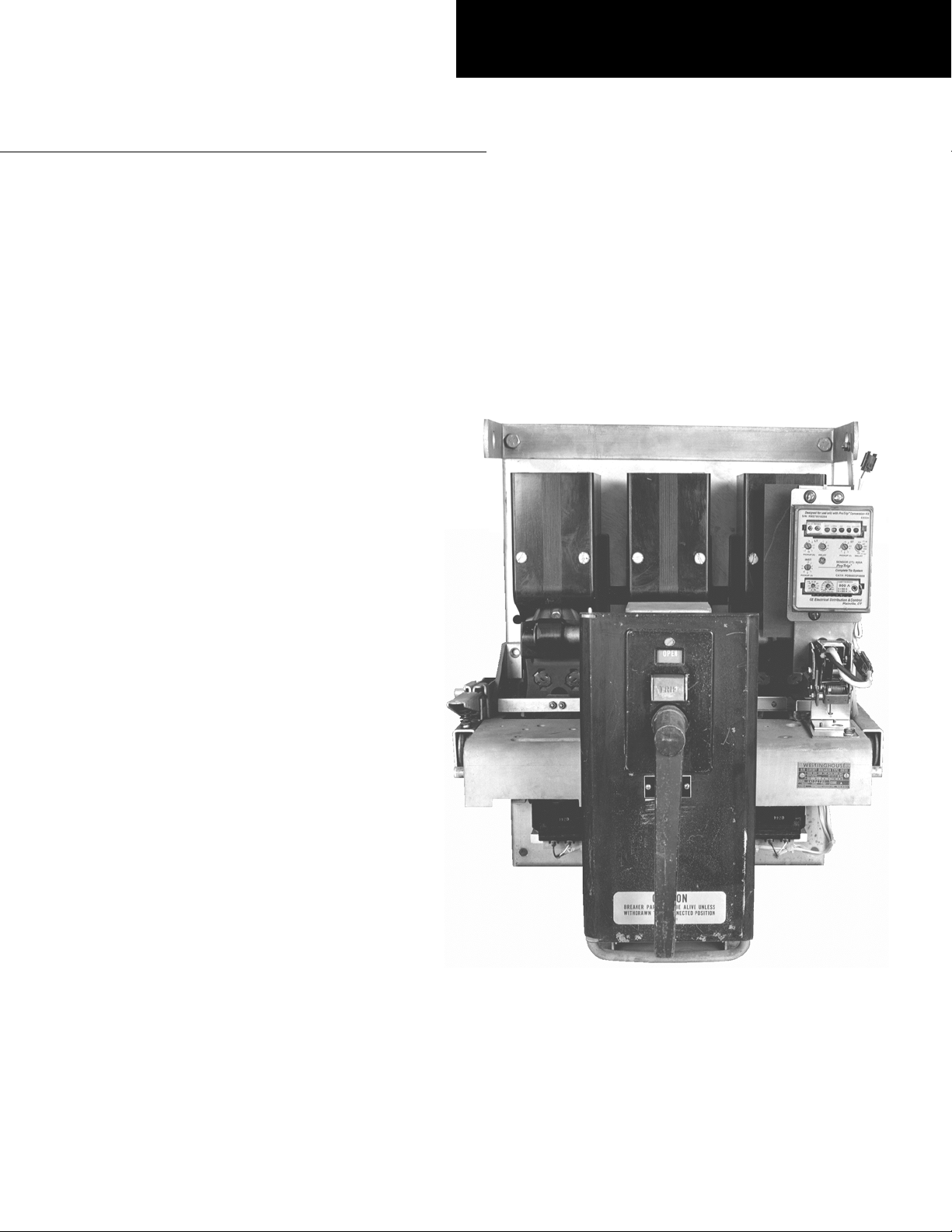
1. Remove the breaker to a clean, well-lighted work
bench and place it upright, so that both the front and
back are easily accessible, as shown in Figure 1.
2. Remove the existing electromechanical trip devices.
3. Assemble the phase sensors (CTs) to their bus
structures.
4. Install the CT assemblies on the breaker.
Removing the Electromechanical Trip
Devices
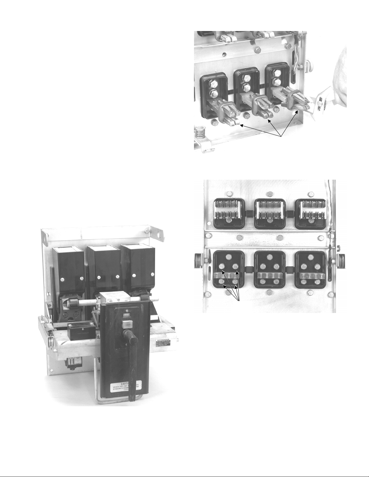
1. On a draw-out breaker, remove the load-side draw-
out contact fingers. Use a pair of pliers to squeeze
the fingers and release them from the load terminals,
as shown in Figure 2.
2. On both a DB-25 and DB-50 breaker, remove and
discard the two
terminal, as shown in Figures 3 and 4.
1
/2-13 bolts above each load
Load-Side
Draw-Out
Fingers
Figure 2. Removal of the load-side draw-out fingers from
a DB-25 breaker.
Figure 1. Westinghouse DB-50 breaker removed from its
enclosure and ready for conversion.
1
/2-13
Bolts
Figure 3. Trip unit mounting bolts to be removed from a
DB-50.
5
Page 6
1
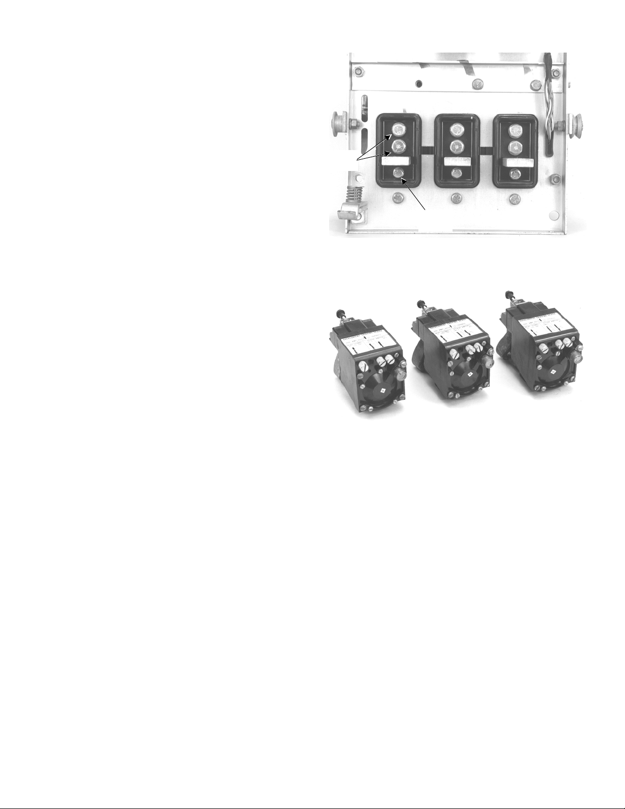
3. On a DB-50 breaker, remove and discard the two
/213 bolts under each load terminal, as shown in
Figure 3.
On a DB-25 breaker, remove and discard the single
3
/8-16 bolt under each load terminal, as shown in
Figure 4.
4. Remove the electromechanical trip devices, shown in
Figure 5, from the frame and discard them. The back
frame is now ready for conversion, as shown in
Figure 6.
1
/2-13
Bolts
3
/8-16
Bolt
Figure 4. Trip unit mounting bolts to be removed from a
DB-25.
Figure 5. Electromechanical trip devices removed from
the breaker.
6
Page 7

Figure 6. DB-50 back frame with the electromechanical
trip devices removed and ready for conversion.
7
Page 8

Installing the Phase Sensors (CTs)
The CTs must be assembled with their associated
copper bus parts before they can be installed onto the
breaker frame in the spaces previously occupied by the
electromechanical trip devices.
1. Slide the CT over the post on the lower copper bus
strap, as shown in Figure 7. Place the insulating
barrier on the top of the CT.
2. On a DB-50 breaker, place the top bus strap over the
insulating barrier and insert a
a flat washer and lock washer, as shown in Figure 9.
Leave the bolt finger tight for now.
On a DB-25 breaker, place the top bus strap over the
insulating barrier and insert a
a flat washer and lock washer, as shown in Figure 9.
Leave the bolt finger tight for now.
1
/2-13 x 11/4" bolt, with
3
/8-16 x 11/4" bolt, with
CT Post
Strap
1
/2-13
Bolt
Insulating
Barrier
CT
Top Bus
Figure 7. Assembling a CT to the bus.
1
/2-13
Bolt
Figure 8. CT assembly for a DB-50 breaker.
3
/8-16
Bolt
Figure 9. CT assembly for a DB-25 breaker.
8
Page 9
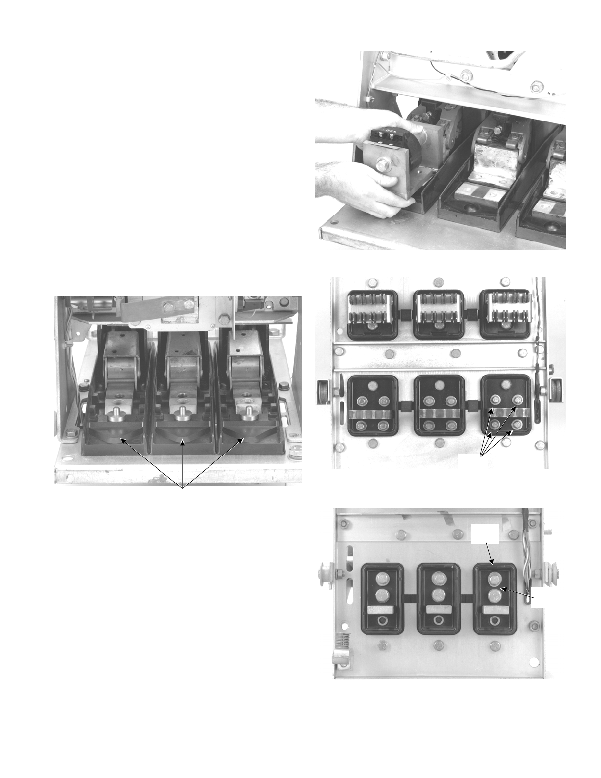
3. On DB-25 breakers only, insert the bus alignment
dowel into the hole below each load terminal, as
shown in Figure 10.
4. Place each CT assembly into the breaker, as shown
in Figure 11, carefully aligning the tapped holes in
the bus with the existing holes in the back frame.
3
5. On a DB-50 breaker, insert the four
/8-16 x 21/2"
bolts, with lock washers and flat washers, through
the back of the breaker into the tapped holes in the
CT assemblies, as shown in Figure 12. Leave the
bolts finger tight for now.
1
On a DB-25 breaker, insert a single
/2-13 x 21/4"
bolt, with a lock washer and flat washer, through the
hole immediately above the load terminal on the back
of the breaker into the tapped hole in the CT
3
assembly, as shown in Figure 13. Insert the
/8-16 x
2" bolt, with a lock washer and flat washer, through
the second hole above the load terminal.
A breaker with all three CT assemblies installed in
shown in Figure 14.
Figure 11. Placing a CT into position on a DB-50 breaker.
Figure 10. CT alignment dowels installed on a DB-25
CT Alignment
Dowel
breaker.
3
-16
/8
Bolts
Figure 12. CT bolts inserted into a DB-50 breaker back
frame.
3
/8-16
Bolt
Figure 13. CT bolts inserted into a DB-25 breaker back
frame.
1
/2-13
Bolt
9
Page 10

6. Tighten the CT assembly mounting bolts, as shown
1
in Figure 15. For a DB-25 breaker, tighten the
3
bolts to 300 in-lb and the
/8-16 bolts to 200 in-lb.
/2-13
Tighten all the CT mounting bolts on a DB-50
breaker to 200 in-lb.
7. On a DB-25 breaker, tighten the bolts on the CT
assemblies to 200 in-lb, as shown in Figure 16.
Tighten the CT assembly bolts on a DB-50 to 300 inlb.
WARNING: Steps 6 and 7 provide critical electrical
integrity connections. The designated bolts must be
correctly tightened for proper operation. Failure to
tighten these bolts properly will cause a breaker failure,
resulting in property damage and/or personal injury.
8. On a draw-out breaker, reinstall the load-side draw-
out fingers removed earlier.
The conversion of the back frame is now complete.
Figure 14. CT assemblies installed into the breaker.
Figure 15. Tightening the CT assembly mounting bolts.
on the rear of the breaker.
Figure 16. Tightening the CT assembly bolts.
10
Page 11

SECTION 4. FRONT FRAME
BREAKER CONVERSION
The front frame conversion of a Westinghouse DB-25 or
DB-50 breaker consists of the following steps, which are
each described in detail:
1. Installing the trip paddle.
2. Installing the trip unit bracket assembly.
3. Adjusting the flux shifter.
4. Installing the wiring harness.
Installing the Trip Paddle
The trip paddle is installed on the right end of the
common trip bar, as shown in Figure 17.
1
1. Align the trip paddle with the hole located 2
inches from the end of the trip bar. On a DB-50
breaker, use the second hole from the end.
1
2. Insert an 8-32 x
/2" screw thought the trip paddle
and trip bar and fasten with the nut with integral lock
washer provided.
3. On a DB-25 breaker, remove the existing snap ring
from the right end of the cross bar. Install the reset
sleeve on the cross bar and secure it with the snap
ring provided, as shown in Figure 18.
/2–31/2
8-32
Screw
Trip
Paddle
Figure 17. Installing the trip paddle onto the trip bar.
Reset
Sleeve
Figure 18. Installing the reset sleeve onto the cross bar
of a DB-25 breaker.
11
Page 12

Installing the Trip Unit Mounting Bracket
The trip unit mounting bracket, shown in Figure 19,
mounts the trip unit and flux shifter to the breaker frame.
1. Mount the trip unit mounting assembly to the right
side of the breaker frame, as follows:
1a. For a DB-50 breaker, mount the bracket
assembly to the existing tapped hole in the
breaker frame with the two
and lock washers provided.
Ensure that the 10-32 pivot screw in the
mounting bracket is inserted through the slot in
the trip paddle, as shown in Figure 20.
1b. For a DB-25 breaker, be sure that the reset arm
on the left side of the flux shifter assembly is
hooked over the cross bar, as shown in Figure
21.
Attach the mounting bracket assembly to the
existing tapped holes in the breaker frame with
1
the two
/4-20 x 3/4" bolts and lock washers
provided.
Attach the spring clamp to the existing hole in the
breaker frame, as shown in Figure 22, with the
1
supplied
/4-20 x 3/4" bolt, flat washer, and lock
washer. Slide the clamp against the base of the
flux shifter assembly, then tighten the bolt.
Connect the spring from the flux shifter assembly
to the clamp.
5
/16-18 x 1/2" bolts
Pivot
Screw
Figure 20. DB-50 trip unit bracket installation.
Reset
Arm
Cross
Bar
Figure 19. Trip unit and flux shifter mounting bracket
assembly.
Figure 21. DB-25 flux shifter reset arm installed on the
cross bar.
12
Page 13

2. Attach the support bracket provided to the top of the
1
trip unit mounting assembly with the
/4-20 x 3/4" bolt
provided, as shown in Figure 23. Use the bracket as
a template to locate the position in the breaker frame
1
to drill a hole to accommodate a
/4" bolt.
3. Attach the support bracket to the breaker frame with
1
/4-20 x 3/4" bolt provided, as shown in Figure 24.
the
The trip unit bracket should be parallel to the breaker
back frame.
NOTE: If an undervoltage device is present on the
breaker, it will have to be relocated.
Fig 23. Drilling the flux shifter support bracket mounting
hole.
Spring
Clamp
Spring
Figure 22. DB-25 spring clamp installed on the breaker
frame.
Figure 24. Installed flux shifter and trip unit mounting
assembly (DB-50).
13
Page 14

Adjusting the Flux Shifter
With the breaker in the CLOSED position, the gap
between the adjustment screw and the trip paddle should
1
/16 inch, as shown in Figure 25. For safety, OPEN
be
1
the breaker before adjusting the screw with a
wrench. CLOSE the breaker to check the adjustment.
WARNING: Be extremely careful when working on a
CLOSED breaker. Do not reach into the mechanism
while adjusting the flux shifter.
Optional Test – The flux shifter may be tested by closing
the breaker and applying a 9 Vdc power source to the
flux shifter leads (the red wire is positive). The breaker
should trip.
/4-inch
Connecting the Trip Unit Wiring Harness
1. Join the four-pin connector on the trip unit harness to
the four-pin connector on the flux shifter.
2. Run the CT leads through the inside of the breaker
frame, as shown in Figure 26. Connect the harness
leads to the screw terminals on each CT. The black
wire (tap) connects to the left terminal and the white
wire (common) to the right terminal.
3. Use the wire ties provided to secure the harness
back against the frame. Tie the harness to each CT
assembly, as shown in Figure 26. Ensure that the
wiring will not interfere with any moving parts.
Wiring
Harness
Gap
Flux Shifter
Adjustment
Screw
Figure 25. Adjusting the flux shifter.
Wire Tie
Figure 26. Wiring harness installed on the CTs.
14
Page 15

Installing the Trip Unit
r
r
1. Place a lock washer and flat washer over each of the
2. Remove the large screw from the rear of the trip unit.
3. Insert the 50-pin female connector on the wiring
4. Place the trip unit and mounting plate in position on
1
three
/4-20 x 13/8" screws provided and insert
through the mounting holes on the trip unit mounting
plate. From the rear of the plate, place a flat washer,
spacer, and O-ring over the screws, as shown in
Figure 27.
Place the trip unit in position on the mounting plate,
with the 50-pin connector aligned with the opening in
the plate. Secure with the large screw, as shown in
Figure 27.
harness into the trip unit connector through the rear
of the mounting plate. Secure to the mounting plate
with the two small screws provided, as shown in
Figure 28.
the support bracket mounted to the breaker. Secure
with the screws in the mounting plate into the tapped
holes in the bracket, as shown in Figure 29.
Configuring the Trip Unit
See DEH-40034 for detailed instructions for setting up
ProTrip trip units.
Harness
Connecto
Figure 28. Harness connector attached to the trip unit.
Mounting
Screw
Trip Unit Screw
50-Pin
Connecto
Figure 27. Trip unit attached to its mounting plate.
Figure 29. Mounting the trip unit on the breaker.
15
Page 16
SECTION 5. FOUR-WIRE GROUND
FAULT OPTION
The ground fault option for four-wire installations requires
the installation of an additional current sensor on the
neutral bus in the equipment. The sensor is connected to
the trip unit through the connector provided in the wiring
harness.
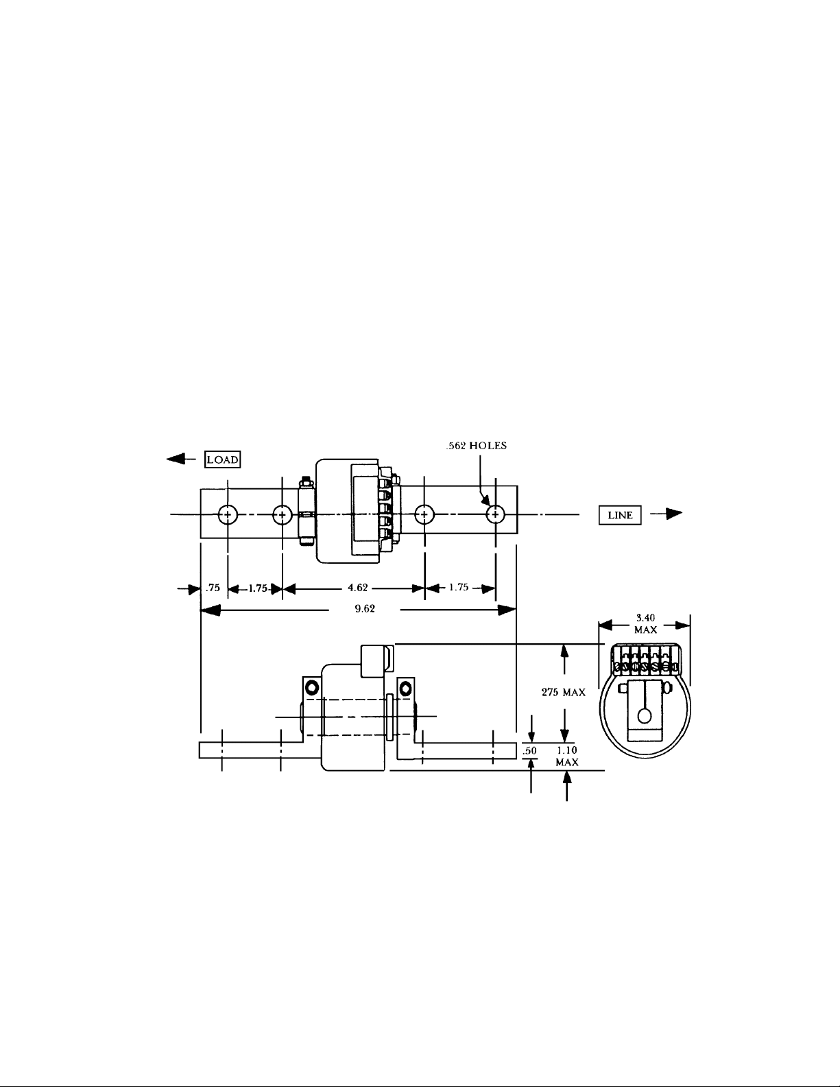
1. Mount the neutral sensor on the outgoing neutral
lead, normally in the bus or cable compartment in the
equipment. Figures 30 and 31 show the outlines of
the neutral sensors for a DB-25 and DB-50 breaker,
respectively.
2. Connect the neutral sensor wire harness to the
correct taps on the sensor. To maintain the same
polarity as the phase sensors, connect the white wire
to the common terminal, black to the tap.
3. Route the wires through the equipment and connect
to the two-pin connector on the trip unit wiring
harness. The wires should be tied to the breaker
frame in an easily accessible location.
Figure 30. Neutral sensor outline for a DB-25 breaker.
16
Page 17
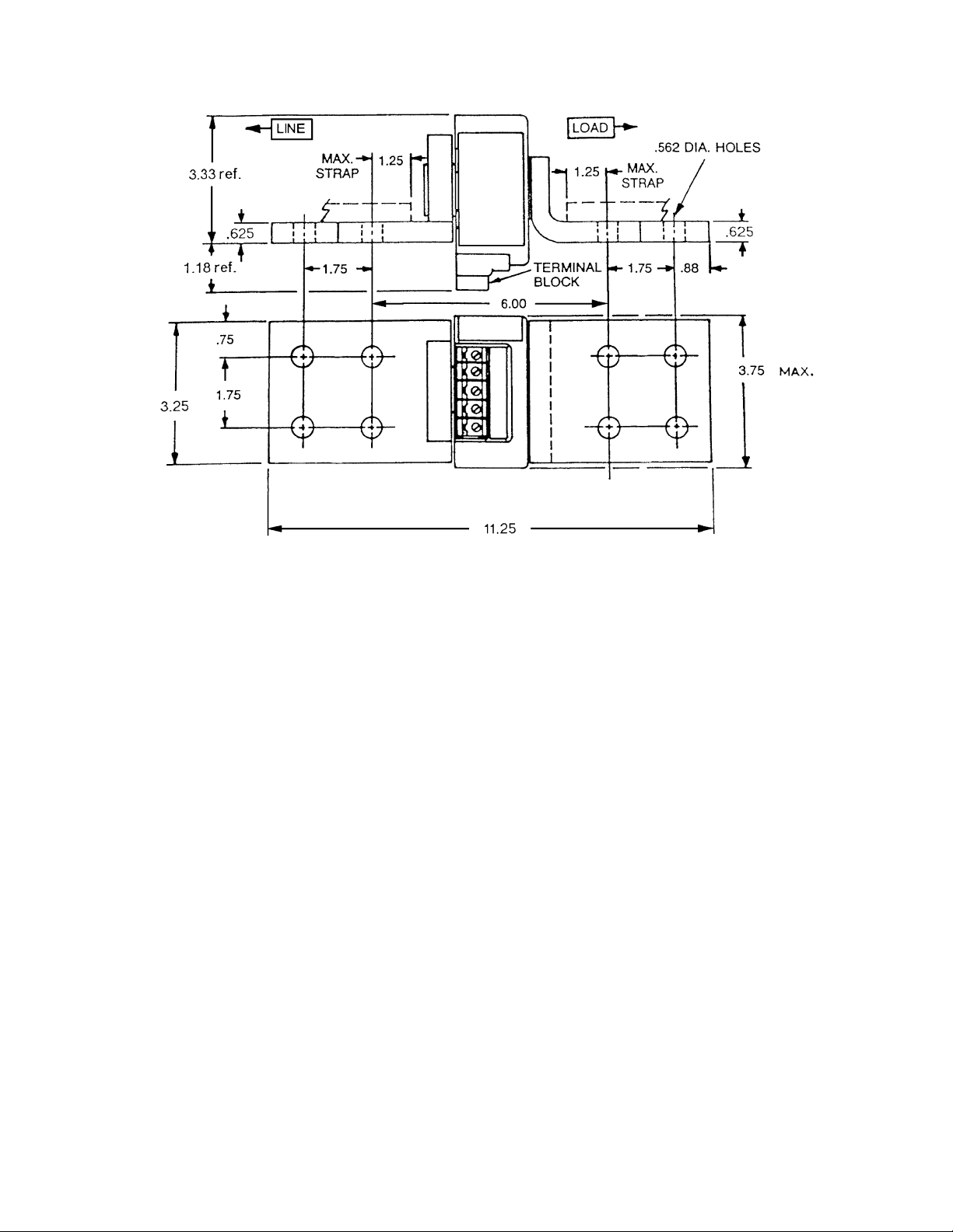
Figure 31. Neutral sensor outline for a DB-50 breaker.
17
Page 18

SECTION 6. TESTING AND TROUBLESHOOTING
WARNING: Do not change taps on the current sensors
or adjust the trip unit settings while the breaker is
carrying current. Failure to adhere to these instructions
will void all warranties.
Testing
Before installing a converted breaker back into service,
perform the following steps:
1. Verify that the trip unit is securely installed by
performing a continuity test on the CT wiring and the
trip unit.
a. Disconnect the black CT wires at each phase
sensor.
b. Check for continuity with a continuity tester or
VOM from the white lead of the phase A CT to the
white lead of the phase B CT.
c. Repeat this continuity test for the white leads of
the phase A and phase C CTs.
d. Measure the resistance across each phase
sensor and compare the values measured to the
values listed in Table 1.
e. Reconnect the black CT leads to all of the phase
sensors. Ensure that this is done before
continuing with performance testing of the
breaker.
CAUTION: In addition to the continuity test described in
Step 1 and before performance testing of the converted
breaker, each phase of the breaker should be primary
injected with a current level of about 10%, but no more
than 20%, of the CT rating.
WARNING: If the converted breaker is energized or
tested by primary injection with a sufficiently high test
current with a loose or open circuit between the CTs
and the trip unit, damage will occur to the trip unit, wire
harness, 50-pin trip unit connector, and CTs. Failure to
adhere to these instructions will void all warranties.
2. Check the insulation on the primary circuit with a
1,000-volt Megger.
3. Measure the resistance across the line and load
terminals for each phase using a micro-ohmmeter or
millivolt tester. If the resistance differs considerably
from phase to phase, the electrical connections may
not be properly tightened or it could also indicate
improper contact wipe.
4. To verify that the breaker has been properly retrofitted, perform a primary injection test on each phase.
This test will check the CTs, bus, wiring harness, flux
shifter, and trip unit as a complete system.
a. A high-current, low-voltage power supply should
be connected across each line and load terminal
to simulate an overcurrent fault.
b. Set the long-time trip at 0.5 to minimize the
breaker stress.
c. When ground fault is installed, the test can be
performed by wiring two adjacent poles in series
or by using the GE Digital Test Kit, cat. no.
TVRMS2. This will prevent the breaker from
tripping because of an unbalanced current flow.
CAUTION: Do not attempt to use GE Test Kit cat. no.
TVTS1 or TVRMS on this trip unit.
Trouble-Shooting
When malfunctioning is suspected, first examine the
breaker and its power system for abnormal conditions
such as the following:
• The breaker is not tripping in response to overcurrent conditions or incipient ground faults.
• The breaker is remaining in a trip-free state because
of mechanical interference along its trip shaft.
• The shunt trip (if present) is activating improperly.
Nuisance Tripping on Ground Fault-Equipped
Breakers
When nuisance tripping occurs on breakers equipped
with ground fault trip, a probable cause is the existence
of a false ground signal. Each phase sensor is connected
to summing circuitry in the trip unit. Under no-fault
conditions on three-wire load circuits, the currents add to
zero and no ground signal is developed. This current
sum is zero only if all three sensors have the same
electrical characteristics. If one sensor differs from the
others (such as by a different rating or wrong tap setting),
the circuitry can produce an output sufficient to trip the
breaker. Similarly, a discontinuity between any sensor
and the trip unit can cause a false trip signal.
The sensors and their connections should be closely
examined if nuisance tripping is encountered on any
breaker whose ProTrip trip unit has previously
demonstrated satisfactory performance. After disconnecting the breaker from all power sources, perform
the following procedure:
1. Check that all phase sensors are the same type
(current range).
2. Verify that the tap settings on all three phase sensors
are identical.
3. Verify that the wiring harness connections to the
sensors have the proper polarity (white lead to
common, black lead to tap), as shown in the cabling
diagram in Figure 32.
4. On ground fault breakers serving four-wire loads,
check that the neutral sensor is properly connected,
18
Page 19

as indicated in Figure 32. In particular, check the
following:
a. Verify that the neutral sensor has the same rating
and tap setting as the phase sensors.
b. Verify continuity between the neutral sensor and
its equipment-mounted secondary disconnect
block. Also check for continuity from the breakermounted neutral secondary disconnect block
through to the trip unit wiring harness connector.
c. If the breaker’s lower studs connect to the power
source, then the neutral sensor must have its load
end connected to the source.
d. Verify that the neutral conductor is carrying only
the neutral current associated with the breaker’s
load current (the neutral is not shared with other
loads).
5. If the preceding steps fail to identify the problem,
then measure the sensor resistances. The appropriate values are listed in Table 1. Since the phase
and neutral sensors are electrically identical, their
resistances should agree closely.
Breaker CT Rating, A Resistance,
ohms
DB-25
DBL-25
DB-50
DBL-50
225
600
800
1500
14–18
40–50
58–79
130–154
Table 1. CT resistance values.
19
Page 20
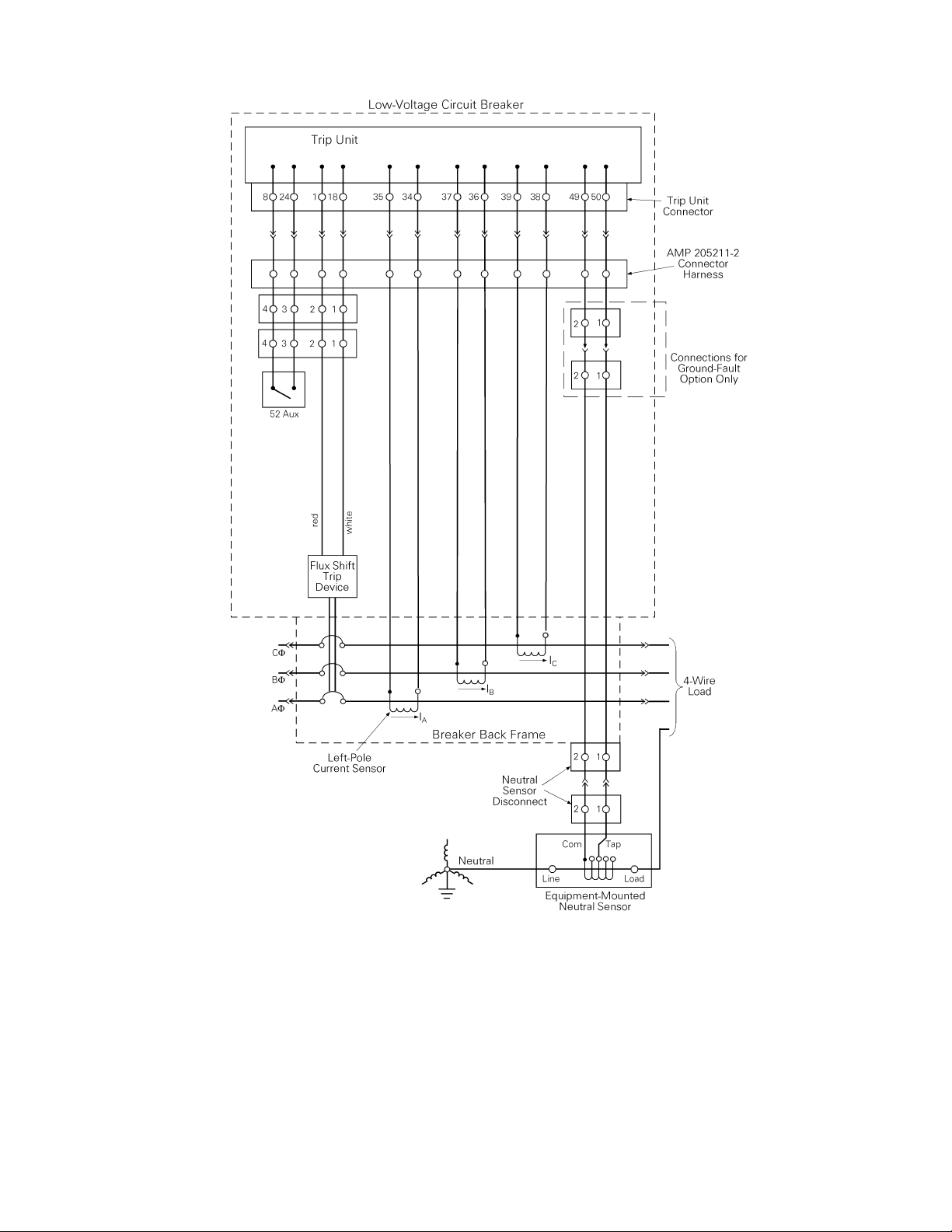
Figure 32. Cabling diagram for ProTrip™ trip units with ground fault on four-wire loads.
20
Page 21

Page 22

These instructions do not cover all details or variations in equipment nor do they provide for every possible contingency
that may be met in connection with installation, operation, or maintenance. Should further information be desired or should
particular problems arise that are not covered sufficiently for the purchaser’s purposes, the matter should be referred to the
GE Company.
GE Industrial Systems
General Electric Company
41 Woodford Ave., Plainville, CT 06062
DEH40031 R03 1099 © 1999 General Electric Company
g
 Loading...