

Page 1
D8R4 expanded I/O
for AV-300i Drives
8 Digital Inputs
4 Relay Outputs
INSTRUCTIONS
GE Industrial SystemsGE Industrial Systems
Page 2

These instructions do not purport to cover all details or variations
in equipment, nor to provide every possible contingency to be met
during installation, operation, and maintenance. If further
information is desired or if particular problems arise that are not
covered sufficiently for the purchaser’s purpose, the matter should
be referred to GE Industrial Systems.
This document contains proprietary information of General Electric
Company, USA and is furnished to its customer solely to assist
that customer in the installation, testing, operation, and/or
maintenance of the equipment described. This document shall
not be reproduced in whole or in part nor shall its contents be
disclosed to any third party without the written approval of GE
Industrial Systems.
© 1999 by General Electric Company, USA. All rights reserved.
Page 3

Table of contents
1. INTRODUCTION ...................................................................... 5
2. MOUNTING ............................................................................. 6
3. TERMINAL BOARD POINTS.................................................... 7
3.1 DIGITAL INPUTS TERMINAL BOARD POINTS .................................... 7
3.2 RELAY OUTPUTS TERMINAL BOARD POINTS..................................... 7
3.3 FUNCTIONAL OVERVIEW ..................................................................... 8
4. TECHNICAL DATA ................................................................... 9
Dimensions and weight ............................................................................... 9
General data ............................................................................................. 10
Digital inputs ............................................................................................. 10
Relay outputs ............................................................................................ 10
Temperature .............................................................................................. 10
5. ACCESSORIES ...................................................................... 11
6. MAXIMUM WIRE SIZES ....................................................... 11
Page 4

Page 5

D8R4
1. INTRODUCTION
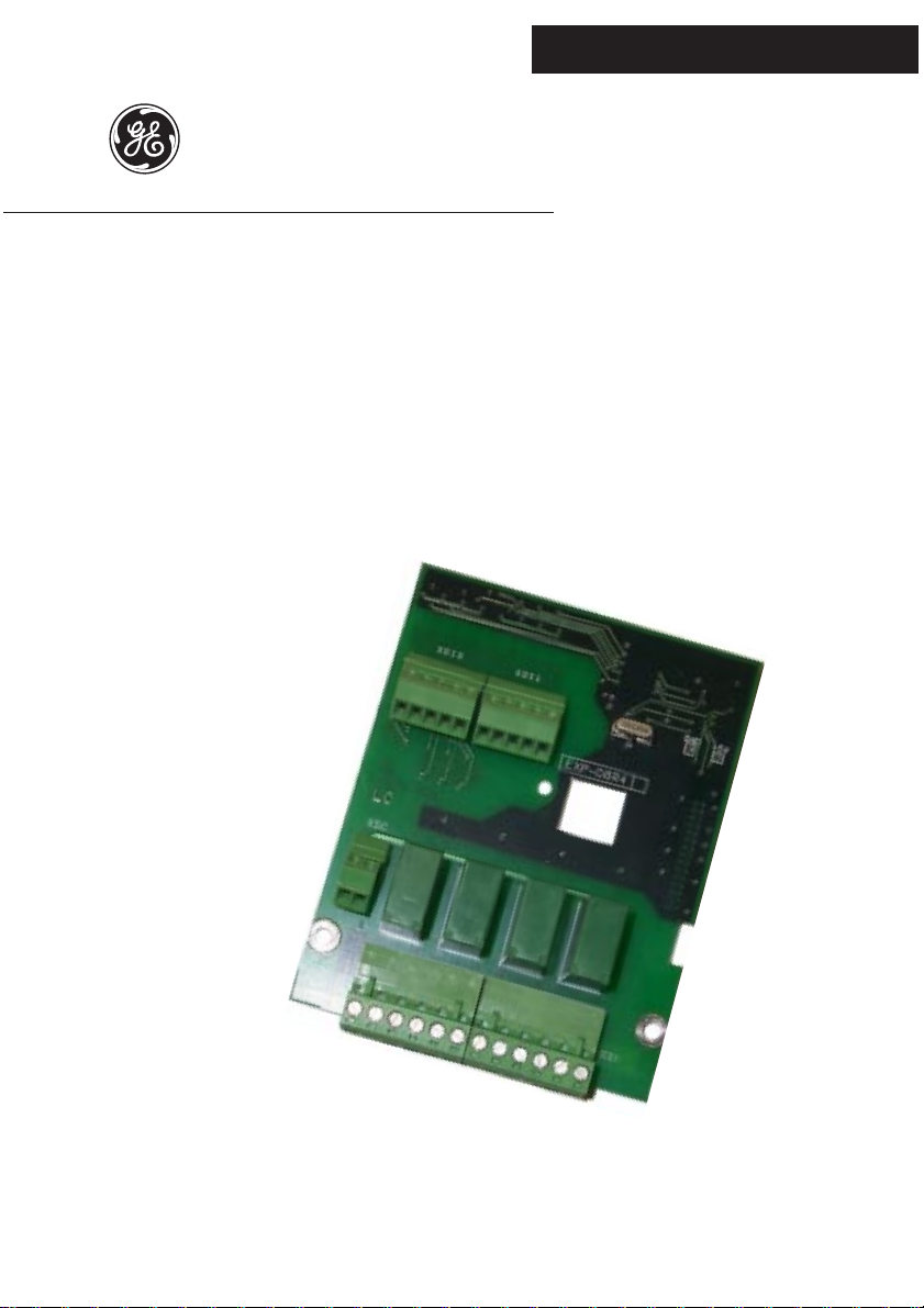
The D8R4 card adds digital Inputs and relay outputs to the drive. It is possible
to use only one I/O expansion card per Drive.
This option card features:
- 8 optocoupled digital inputs 15V up to 30VDC
- 4 relay outputs with 250V max dry contact, 1 N.O.- 1N.C. contact per relay
Front side
Back side
—————— I/O Expansion card ——————
5
Page 6

SIEI
2. MOUNTING
The D8R4 card is supplied with standoffs and the cable for connection between
regulation and expansion card .
1 . Switch the drive off.
2. Fasten the D8R4 card to the drive regulation board by means of screws
(B) and standoffs (A).
3. The D8R4 card is connected to the regulator card through the XH
connector using the supplied cable. The power supply (+5V) and the
control signals are provided by the drive via the XH connector.
4 . Switch on the drive.
6
—————— I/O Expansion card ——————
Page 7

D8R4
3. TERMINAL BOARD POINTS
3.1 DIGITAL INPUTS TERMINAL BOARD POINTS
Connectors XDI0 and XDI1 have different ground connection.
DIGITAL INPUTS
Connector
Terminal 31 32 33 34 35 36 37 38 39 40
Function DI0 DI1 DI2 DI3 GND DI4 DI5 DI6 DI7 GND
3.2 RELAY OUTPUTS TERMINAL BOARD POINTS
Relay outputs need a +24V (60mA) supply voltage.
The Drive TB can be used to supply 24VDC power. AV-300i 24VDC supply
maximum output = 120 mA total including Encoder, LAN, Expansion card and
DGF (or 350 mA without DGF).
RELAY OUTPUTS
Connector
Relay
Terminal 114 111 112 214 211 212
Function N.Open COM N.Closed N.Open COM N.Closed
R0 R1
XCQ0
XDI1XDI0
exp10
RELAY OUTPUTS
Connector
Relay
Terminal 314 311 312 414 411 412
Function N.Open COM N.Closed N.Open COM N.Closed
RELAY OUTPUTS POWER SUPPLY
Connector
Terminal 100 101
Function 0V power supply +24V power supply
—————— I/O Expansion card ——————
R2 R3
XCQ1
exp20
XSC
exp30
7
Page 8

3.3 FUNCTIONAL OVERVIEW
SIEI
DIO
31
DI1
32
DI2
33
DIGITAL INPUTS
DI3
34
GND
35
DI4
36
DI5
37
DI6
38
DI7
39
GND
40
DIGITAL INPUTS
CONNECTOR XSC
CONNECTOR XDIO
CONNECTOR XDIO
POWER SUPPLY
RELAY OUTPUTS
CONNECTOR XCQ00
RELAY OUTPUTS
CONNECTOR XCQ01
I/O available depending on drive firmware version
+24V
0V (COM)
N.Closed
N.Open
COM
N.Closed
N.Open
COM
N.Closed
N.Open
COM
N.Closed
N.Open
COM
101
100
112
114
111
212
214
211
312
314
311
412
414
411
Drive firmware 1.X from 2.X
Digital Inputs 4 8
Relay Outputs 4 4
exp50
8
—————— I/O Expansion card ——————
Page 9

Dimensions and weight
92 mm (3.6”)
D8R4
4. TECHNICAL DATA
118 mm (4.6”)
Dimensions ________________________________ 118 mm [4.6 inches] x 92 mm
[3.6 inches]
Weight _____________________________________ 113 g [ 4 oz]
—————— I/O Expansion card ——————
9
Page 10

SIEI
General data
I/O Scan time _______________________________ 2ms
Internal power supply from the drive ____________ +5V
Digital inputs
Input type _________________________________ Voltage/Optocoupled
Inputs no. __________________________________ 8 (2 groups of 4 inputs)
0V connection _______________________________ different 0V for the groups
Voltage input value ___________________________ 15 up to 30V
Current input value___________________________ 4.5 up to 9mA
Relay outputs
Typ e ______________________________________ Dry contacts
Output no. _________________________________ 4
Max contact Voltage / Current value ______________ 250V max , 5A max
- 250VAC, 4 A ohmic load, 1.2A inductive load (cosphi=0.4 up to 0.7)
- 115VAC, 5 A ohmic load, 2.6A inductive load (cosphi=0.4 up to 0.7)
- 24VDC, 400mA
Min contact Voltage / Current value ______________ 20V , 50mA (*)
Relay driving type ___________________________ open emitter optocoupled
Relay power supply (external) __________________ +24V -20% +50% @ 20°C
+ 24V power requirements _____________________ 60mA max
(*) N
OTE!
These outputs are not suitable for switching hi fidelity analog
signals management.
Temperature
Storage temperature: __________________________ -20°... +70°C (-68...+158°F)
Operating temperature:________________________ 0°... +55°C (32...+131°F)
These temperatures are adequate to those of the drive, to which the card is connected.
10
—————— I/O Expansion card ——————
Page 11

D8R4
5. ACCESSORIES
Terminals XCQ0,XCQ1____________________ Type PHOENIX CONTACT
6 contacts MSTB2, 5/ 6 ST5,08
1757051
Type WIELAND 6 contacts
25.340.3653.0
Terminals XDI0,XDI1 _____________________ Type PHOENIX CONTACT
5 contacts MC1,5/5 ST3,81
1803604 or equivalent.
Terminals XSC ___________________________ Type PHOENIX CONTACT
2 contacts MC1,5/2 ST3,81
1803578 or equivalent.
6. MAXIMUM WIRE SIZES
2
Terminals on connector
XSC, XDI0, XDI1 0.14…1.5 28 … 16
XCQ0, XCQ1 0.2…2.5 24 … 12
mm
AWG
exp40
—————— I/O Expansion card ——————
11
Page 12

MANUALE D8R4 GEI-100425 03/99
Rev. 0.0 / 17.3.99
We bring good things to life.
GEI-100425 Rev. 0.0 (03/99)
GE Industrial Systems
Internet Address: http://www.ge.com
 Loading...