

Page 1
D14A4F expanded I/O
for AV-300i Drives
8 Digital Inputs
6 Digital Outputs
2 Analog Inputs
2 Analog Outputs
1 Frequency Input
INSTRUCTIONS
GE Industrial SystemsGE Industrial Systems
Page 2

These instructions do not purport to cover all details or variations
in equipment, nor to provide every possible contingency to be met
during installation, operation, and maintenance. If further
information is desired or if particular problems arise that are not
covered sufficiently for the purchaser’s purpose, the matter should
be referred to GE Industrial Systems.
This document contains proprietary information of General Electric
Company, USA and is furnished to its customer solely to assist
that customer in the installation, testing, operation, and/or
maintenance of the equipment described. This document shall not
be reproduced in whole or in part nor shall its contents be disclosed
to any third party without the written approval of GE Industrial
Systems.
© 1999 by General Electric Company, USA. All rights reserved.
Page 3

Table of contents
1. INTRODUCTION ...................................................................... 5
2. MOUNTING ............................................................................. 7
3. TERMINAL BOARD POINTS.................................................... 8
3.1 DIGITAL INPUTS TERMINAL BOARD POINTS .................................... 8
3.2 DIGITAL OUTPUTS TERMINAL BOARD POINTS ................................. 8
3.3 ANALOG INPUTS TERMINAL BOARD POINTS ................................... 8
3.4 ANALOG OUTPUTS TERMINAL BOARD POINTS ................................ 9
3.5 ENCODER CONNECTION ...................................................................... 9
3.6 FUNCTIONAL OVERVIEW ................................................................... 10
4. JUMPERS ............................................................................. 11
5. TECHNICAL DATA ................................................................. 12
Dimensions and weight ............................................................................. 12
General data ............................................................................................. 13
Digital inputs ............................................................................................. 13
Digital outputs ........................................................................................... 13
Analog inputs ............................................................................................ 13
Analog outputs .......................................................................................... 14
Encoder interface ...................................................................................... 14
Temperature .............................................................................................. 14
6. ACCESSORIES ...................................................................... 15
7. MAXIMUM WIRE SIZES ....................................................... 15
Page 4

Page 5
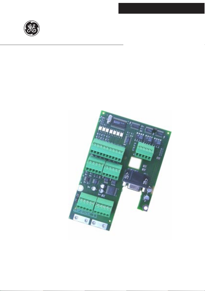
D14A4F
1. INTRODUCTION
The D14A4F card is an AV-300i drive option used to add digital inputs, digital
outputs, analog inputs, analog outputs and a second optocoupled encoder
input to the drive. It is possible to use only one I/O expansion card per Drive.
This option card features:
- 8 optocoupled digital inputs 15V up to 30VDC
- 6 optocoupled digital outputs 15V up to 30VDC
- 2 analog inputs ±10V or 0 up to20mA or 4 up to 20mA
- 2 analog outputs ±10V
- 1 optocoupled digital encoder input
Front side
—————— I/O Expansion card ——————
5
Page 6

GEI-100426
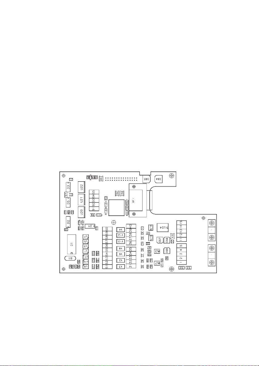
Back side
6
—————— I/O Expansion card ——————
Page 7

D14A4F
2. MOUNTING
The D14A4F card is supplied with standoffs and the cable for connection
between regulation and expansion card .
1 . Switch the drive off.
2 . Fasten the D14A4F card to the drive regulation board by means of screws
(B) and standoffs (A).
3. The D14A4F card is connected to the regulator card through the XH
connector using the supplied connector. The power supply (+5V) and the
control signals are provided by the drive via the XH connector.
4 . Switch on the drive.
—————— I/O Expansion card ——————
7
Page 8

GEI-100426
3. TERMINAL BOARD POINTS
3.1 DIGITAL INPUTS TERMINAL BOARD POINTS
Connectors XDI0 and XDI1 have different ground connection.
DIGITAL INPUTS
Connector
Terminal 31 32 33 34 35 36 37 38 39 40
Function DI0 DI1 DI2 DI3 GND DI4 DI5 DI6 DI7 GND
3.2 DIGITAL OUTPUTS TERMINAL BOARD POINTS
Digital outputs need a +15V…+24V supply voltage.
T erminal 60 is power supply, terminal 55 is the common power supply.
DIGITAL OUTPUTS
Connector
Terminal 51 52 53 54 55 56 57 58 59 60
Function DQ0 DQ1 DQ2 DQ3 COM DQ4 DQ5 * * PWR
* = Reserved
XQD
XDI1XDI0
expD10
expD20
3.3 ANALOG INPUTS TERMINAL BOARD POINTS
Differential analog inputs are available.
ANALOG INPUTS
Connector
Terminal 12345
Function AI0+ AI0- AI1+ AI1- GND
8
—————— I/O Expansion card ——————
XAI
expD30
Page 9

D14A4F
3.4 ANALOG OUTPUTS TERMINAL BOARD POINTS
ANALOG OUTPUTS
Connector
Terminal 11 12 13 14 15
Function AQV0 GND AQV1 GND GND
XAQV
expD40
3.5 ENCODER CONNECTION
The D14A4F expansion board adds a second digital encoder input via a 15
pins high density connector (VGA type). External power for the encoder (+5V
or +15V/24V) can be supplied thru terminals 93, 94, 95.
ENCODER
Connector
PIN 1 2 345678
B-
Signal
I/O IOIIIIOI
(5V)
+24VE0+
(5V)0-(5V)A+(5V)A-(5V)
XFI
0VE
B+
(5V)
Connector
PIN 9 10 1112131415
Signal +5VE
I/O OI IIIII
WARNING!
A+
(15V
up to
24V)
5V and 15V-30V encoder signals cannot be intermixed in
A-
(15V
up to
24V)
B+
(15V
up to
24V)
XFI
B-
(15V
up to
24V)
the same connector.
ENCODER SUPPLY
Connector
Terminal 91 92 93 94 95
Signal
—————— I/O Expansion card ——————
C1+ C1- +5VE +24VE 0VE
XSI
O+
(15V
up to
24V)
O(15V
up to
24V)
expD50
expD60
9
Page 10

3.6 FUNCTIONAL OVERVIEW
GEI-100426
31
32
33
34
35
36
DIO
DI1
DI2
DI3
GND
DI4
DIGITAL INPUTS
CONNECTOR XDIO
DIGITAL OUTPUTS CONNECTOR XDQ
37
38
39
40
DI5
DI6
DI7
GND
DIGITAL INPUTS
CONNECTOR XDI1
0V (COM)
+24V (PWR)
DQ0
DQ1
DQ2
DQ3
DQ4
DQ5
55
60
51
52
53
54
56
57
10
1
2
3
4
5
91
92
93
94
95
AIO+
AIO-
AI1+
AI1-
GND
C1+
C1-
+5VE
+24VE
0VE
ENCODER
QUALIFIER
A+ (15V up to 24)
SUPPLY
ENCODER
OUTPUTS
ANALOG INPUTS
CONNECTOR XAI
ENCODER (Frequency input)
A- (5V)
B- (5V)
+24VE
0+ (5V)
A+(5V)
0- (5V)
0VE
B+ (5V)
+5VE
ANALOG
CONNECTOR XAQV
6
1
10
5
11
15
AQV0
GND
AQV1
GND
GND
A- (15V up to 24)
B+ (15V up to 24)
B- (15V up to 24)
O+ (15V up to 24)
O- (15V up to 24)
11
12
13
14
15
—————— I/O Expansion card ——————
Page 11

D14A4F
4. JUMPERS
EXP-D14A4F board
Name Default
S2 Adaptation to the input signal of analog input 0 OFF
ON 0…20mA/4…20mA
OFF
0 … 10V / -10V … +10V
S3 Adaptation to the input signal of analog input 1
ON 0…20mA/4…20mA
OFF
0 … 10V / -10V … +10V
S7 ON 0 Channel included in the encoder loss logic
OFF
0 Channel not included in the encoder loss logic
Set Jumper to ON when encoder loss detection is used also for zero channel.
(Alarm active only if a digital encoder with all A, Anot, B, Bnot channels and
+15V/24V power supply is used).
I/O available depending on drive firmware version
Description
OFF
OFF
expD70
Drive firmware 1.X from 2.X
Digital Inputs 4 8
Digital Outputs 6 6
Analog Inputs - 2
Analog Outputs 2 2
Encoder Input 1 1
—————— I/O Expansion card ——————
expD75
11
Page 12

Dimensions and weight
142.24
GEI-100426
5. TECHNICAL DATA
92.08
Dimensions _________________________________ 142.24mm [4.8 inches] x 92.08
mm [3.6 inches]
W eight _____________________________________ 97g [ 3.4 oz]
12
—————— I/O Expansion card ——————
Page 13

D14A4F
General data
I/O scan time________________________________ 2ms
Internal power supply from the drive ____________ +5VDC, ±18VDC
NOTE !
The Drive TB can be used to supply 24VDC power. AV-300i
24VDC supply maximum output = 120 mA total including
Encoder, LAN, Expansion card and DGF (or 350 mA without
DGF).
Digital inputs
Input type _________________________________ Voltage/Optocoupled
Inputs no. __________________________________ 8 (2 groups of 4 inputs)
0V connection _______________________________ different 0V for the groups
Voltage input value ___________________________ 15 up to 30V
Current input value___________________________ 4.5 up to 9mA
Digital outputs
Output type ________________________________ open emitter/Optocoupled
Pull down __________________________________ 10 kΩ
Outputs no. ________________________________ 6
External power supply ________________________ 15 up to 30V
Output current ______________________________ 50mA max for any output
Output voltage ______________________________ Power supply less 1V @50mA
Analog inputs
Input type (differential) _______________________ Voltage or Current
Inputs no. __________________________________ 2
Input voltage (con ingresso in tensione) ___________ ±10V
Current requirements (with Voltage ref in input) ____ <0.5mA
Input current (with current ref in input) __________ 0 up to 20mA/4 up to 20mA
Bandwidth _________________________________ 100Hz
—————— I/O Expansion card ——————
13
Page 14

GEI-100426
Analog outputs
Output type ________________________________ Voltage
Outputs no. ________________________________ 2
Max Output voltage __________________________ ±10V
Output current ______________________________ 5mA max
Bandwidth _________________________________ 265Hz
Encoder interface
Interface type _______________________________ optocoupled digital encoder
input interface
Standard inputs______________________________ A+,A-,B+,B-,0+,0Additional input for encoder qualifier ____________ C1+,C1- (optocoupled)
Encoder power supply ________________________ +5V or 15V/24V, selectable
Voltage input range High level (on pin) ) (U
Voltage input range Low level (on pin) ) (U
Current input value (@ 5V, on pin) ______________ 10mA
Current input value (@ 15V, on pin) _____________ 8mA
Current input value (@ 24V, on pin) _____________ 13mA
Voltage (Current) value additional input for encoder qualifier
__________________________________________ 15 up to 30V (4.5up to 9mA)
)_____ 2.5V up to 5.25V (@5V)
High
9 up to26V (@15V/24V)
) _____ <= 0.8V (@5V)
Low
<= 1.6V (@15V÷24V)
No. encoder pulses ___________________________ 600 up to 9999
Max Frequency input _________________________ 150kHz
Temperature
Storage temperature: __________________________ -20°... +70°C (-68...+158°F)
Operating temperature:________________________ 0°... +55°C (32...+131°F)
These temperatures are adequate to those of the drive, to which the card is connected.
14
—————— I/O Expansion card ——————
Page 15

D14A4F
6. ACCESSORIES
XFI Connector ___________________________ 15 poles high density (VGA type),
male.
XFI connector cover _______________________ Standard 9 poles low profile.
Example manufacturer code:
AMP: 0-748676-1
3M: 3357-6509
Terminals XDI0,XDI1, XAI, XAQV, XSI ______ Type PHOENIX CONTACT
5 contacts MC1,5/5 ST3,81
1803604 or equivalent.
Terminals XDQ __________________________ Type PHOENIX CONTACT
10 contacts MC 1,5/10 ST3,81
1803659 or equivalent.
7. MAXIMUM WIRE SIZES
2
Terminals on connector
XDQ, XDI0, XDI1,XAI,XAQV,XFI 0.14 … 1.5 28 … 16
—————— I/O Expansion card ——————
mm
AWG
expD80
15
Page 16

MANUALE D14A4F GEI-100426 03/99
Rev. 0.0 / 14.5.99
1S5G18
We bring good things to life.
GEI-100426 Rev. 0.0 (03/99)
GE Industrial Systems
Internet Address: http://www.ge.com
 Loading...