

Page 1
Definite Purpose
Contactors & Starters
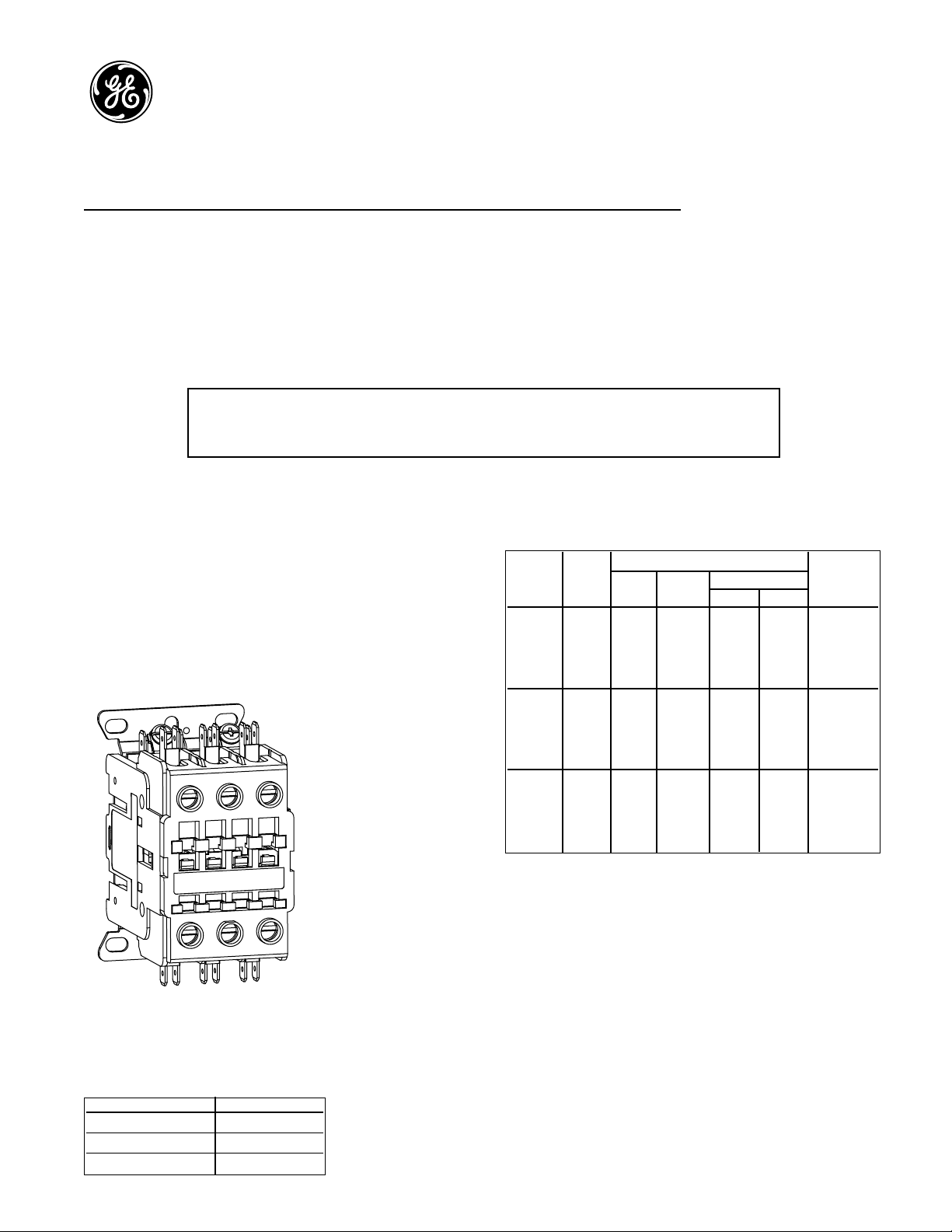
CR453A Series Contactors
CR454A Series Starters
Description
GE’s CR453A magnetic contactors provide a 2- or 3-pole
device for use in air conditioning units or other general
purpose applications. These instructions give information
about ratings, installation, accessories and wiring, overload
relay may be added if needed. Factory assembled starters
CR454A include overload relay.
Motor branch circuit and control circuit overcurrent
protection should be supplied in accordance with the
National Electrical Code or local code as required. CR453A
contactors are suitable for use on a circuit capable of
delivering not more than 5,000 RMS symmetrical amperes,
600 volts maximum when protected by fuses or a circuit
breaker having an interrupting rating not less than 5,000
RMS symmetrical amperes.
Use 75° C copper conductors only.
Ratings – Full Voltage, Non-Reversing
Frame
Ratings Resistive
Size
VAC
FLA LRA
Horsepower Rating Per
1 PH 3 PH Pole
120 150 2 –
CR453AB
240
25
150 3 7.5
35
480 125 – 10
600 100 – 10
120 180 2 –
CR453AC
240
30
180 5 10
40
480 150 – 15
600 120 – 15
120 240 3 –
CR453AD
240
40
240 7.5 10
50
480 200 – 20
600 160 – 20
Caution: Before installing in a nuclear application, determine that the product is intended for such use.
Warning: Disconnect power before installing or servicing.
Typical CR453A Series contactor
Power Terminal Tightening Torque (lbs.-in.)
Terminal Type Torque Values
Box Lug 40
Pressure Plate 20
Binding Screw 20
Page 2
Contactor Installation
Before connecting to power supply:
1. Remove all packing.
2. Operate movable magnet and operating arm by
pressing down on the operating arm from the front
or side of the contactor to assure free movement.
3. Mount starter on a sturdy vertical support.
4. Make electrical connections as per wiring diagram.
For quick connect wiring, use UL recognized insulated
terminals.
Starter Installation
1. Remove all packing.
2. Motors with service factor of 1.15 or greater.
• Select overload relay as per the FLA shown in the
motor nameplate.
• Adjust the front mounted tripping current setting
dial to the motor FLA.
2. Motors with service factor less than 1.15
• Select overload relay as per the formula: Motor FLA
(shown in the motor plate) x 0.09.
• Adjust the front mounted tripping current setting dial
to the result of the above mentioned motor FLA.
3. Operate movable magnet and operating arm by pressing
down on the operating arm from the front or side of the
contactor to assure free movement.
4. Mount starter on a sturdy vertical support.
5. Make electrical connections as per wiring diagram.
For quick connect wiring, use UL recognized insulated
terminals.
6. Select the four modes by means of a front selector
lever.
7. Overload relays features tripping indicator, independent
& double break auxiliary tripping contacts (1NO+1NC)
with welding check lever.
8. Overload relay features thermal protection against
balanced overload, differential protection against
unbalanced overloads and also ambient temperature
compensation.
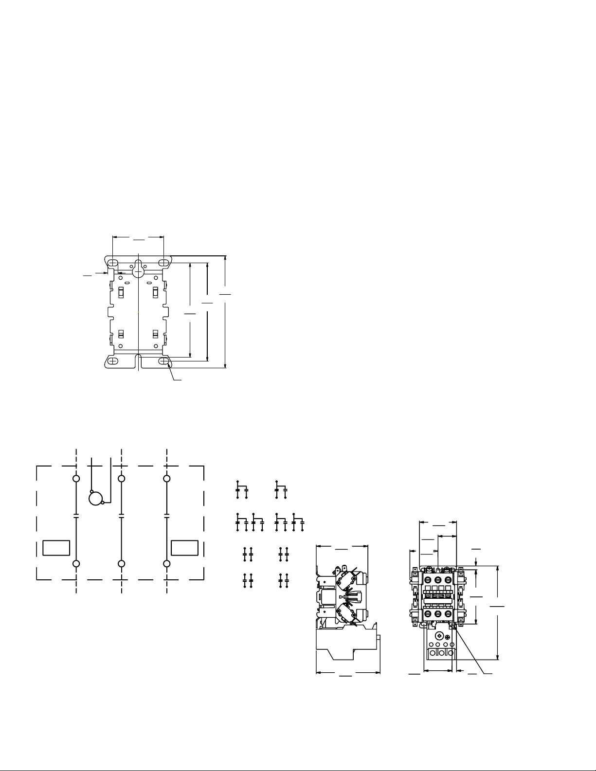
Mounting Hole Dimensions
Contactor Wiring Diagram
CR454A Series Starter Dimensions
1.70
43,2
.35
8,9
3.75
95,3
3.28
83,3
3.16
80,3
MOUNTING HOLES FOR
#10 SCREWS(6 PLACES)
3 PHASE LINE CONNECTION
CONTROL
L1 L2 L2
OPTIONAL
AUX
CONTACTS
VOLTAGE
M
T1 T2 T2
3 PHASE LINE CONNECTION
FRONT VIEW
OPTIONAL
AUX
CONTACTS
NOMENCLATURE
M-LINE CONTACTOR
NO-NORMALLY OPEN
NC-NORMALLY CLOSED
AUX CONTACT OPTONS
TYPE
LEFT
SIDE
C
1 SPDT
NC N
2 SPDT
NC N NC N
2 NO
1 NO-1 NC
RIGHT
SIDE
C
NC N
CC
C
NC N NCCN
13 23
24
131421
2214
33
34 44
31
32
2.25
57,0
1.12
43
43
44
3.13
79,4
1.71
43,3
28,5
.24
6,0
3.28
83,3
5.68
144,3
3.87
98,2
1.70
43,2
.27
6,9
MOUNTING HOLES FOR
#10 SCREWS(6 PLACES)
Page 3

CR453A Accessories Standard
Accessory Contacts (with quick connects on C-2000
side-mount accessories) accessories
600V side-mount aux. 1NO-1NC CR453XC611 BCLL11
contact block 2NO CR453XC620 BCLL20
250V side-mount aux 1 SPDT CR453XC211 —
contact block 2 SPDT CR453XC222 —
600V front-mount aux. 1NO BCLF10 BCLF10
contact block 1NC BCLF01 BCLF01
Mechanical interlock,
side-mount
2NC CR453XM602 BEL02
Accessories
Check for Welded Contacts in Overload Relay
Disconnect power from device and control wiring from the
terminals of the relay. Connect the bell set or resistance-
measuring instrument across the relay terminals. Depress
and release the reset arm to ensure the relay is reset. In this
condition there should be continuity between the terminals.
In the tripped condition, the circuit between the terminals
should be open indicating the contacts are operating
normally. Remove the bell set or resistance measuring
apparatus, rewire the relay terminals and reset the relay for
normal operation.
For further technical details on overload relays, refer to
installation instructions GEH-6237A.
Accessory Kit Installation
Overload Relays
Starter Wiring Diagram
Installation
Catalog No.
Current Range (A)
Contactor
Class 10 Class 20
RT1B RT12B 0.16-0.26
RT1C RT12C 0.25-0.41
RT1D RT12D 0.4-0.65
RT1F RT12F 0.65-1.1
RT1G RT12G 1.0-1.5
RT1H RT12H 1.3-1.9
RT1J RT12J 1.8-2.7
CR453AB, RT1K RT12K 2.5-4.1
AC, AD RT1L RT12L 4.0-6.3
RT1M RT12M 5.5-8.5
RT1N RT12N 8-12
RT1P RT12P 10-16
RT1S RT12S 14.5-18
RT1T RT12T 17.5-22
RT1U RT12U 21-26
CR453AC, AD RT1V RT12V 25-32
CR453AD RT1W RT12W 30-40
Typical 250V side auxiliary contact kit.
Typical 600V side auxiliary contact kit.
L1
WIRE B
REMOTE
CONTROL
1
OPTIONAL
AUX
CONTACTS
L1
M
96
95
98
97
T1 T2 T3
CONTROL CIRCUIT FUSING
(IF USED)
L2
L1
96
1
NOTE: ADDITIONAL CONTROL CIRCUIT PROTECTION
MAY BE REQUIRED.PREFER TO NATIONAL
ELECTRIC CODE OR LOCAL CODES.
FOR SEPERATE CONTROL SOURCE-OMIT WIRES A AND B.
CONNECT CONTROL SOURCE TO 1 ON CONTROL DEVICE.
AND 96 ON OVERLOAD RELAY.
L2
WIRE A
L2
MOTOR
L3
FRONT VIEW
L3
OPTIONAL
AUX
CONTACTS
AUX CONTACT OPTONS
TYPE
1 SPDT
2 SPDT
2 NO
1 NO-1 NC
NOMENCLATURE
M-LINE CONTACTOR
OL-THERMAL OVERLOAD RELAY
SPDT-SINGLE POLE DOUBLE THROW
NO-NORMALLY OPEN
NC-NORMALLY CLOSED
L1 L2
1
REMOTE
CONTROL
LEFT
SIDE
C
NC N
C
NC N NC N
NC N NCCN
13 23
24
131421
2214
ELEMENTARY
M
RIGHT
SIDE
C
NC N
CC
OL
33
34 44
31
32
43
43
44
9695
Page 4

GE Industrial Systems
General Electric Company
41 Woodford Avenue, Plainville, CT 06062
www.GEindustrial.com
© 2001 General Electric Company
e-DEH-40445 0801
These instructions do not purport to cover all details or variations in equipment nor to provide for every possible contingency to be met in connection
with installation, operation or maintenance. Should particular problems arise which are not covered sufficiently for the Purchaser’s purposes the
matter should be referred to the nearest GE Industrial Systems sales office.
Front-Mount Auxiliary Contacts Side-Mount Auxiliary Contacts
Overload Relays
Disassembly
Mechanical
interlock
2-Speed Controllers
Assembly
1
2
 Loading...