

Page 1
CPS6000-M2 Frame-Mounted Battery Plant
Model H5694720
Product Manual
Select Code 167-793-112
Comcode CC848802595
Issue 8
January 2008
Page 2

Notice:
The information, specifications, and procedures in this manual are subject to change
without notice. Lineage Power assumes no responsibility for any errors that may appear
in this document.
© 2008 Lineage Power
All International Rights Reserved
Printed in U.S.A.
Page 3

CPS6000-M2 Installation Guide H5694720
Table of Contents
1 Introduction.................................................................................................................... 5
Document Objectives...................................................................................................... 5
Additional Product Documentation ................................................................................ 5
Customer Service Contacts............................................................................................. 6
2 Product Description....................................................................................................... 7
Architecture..................................................................................................................... 8
Millennium II Controller................................................................................................. 9
Rectifier Shelves ........................................................................................................... 10
QS-Series Rectifiers...................................................................................................... 12
QS-Series Ringers......................................................................................................... 12
AC Input........................................................................................................................ 14
Battery Options and Monitoring Features..................................................................... 14
DC Distribution and Battery Termination .................................................................... 15
Specifications................................................................................................................ 16
3 Safety............................................................................................................................. 21
Safety Statements.......................................................................................................... 21
Warning Statements and Safety Symbols..................................................................... 23
Precautions.................................................................................................................... 24
Handling Batteries ........................................................................................................ 25
Special Installation Notes ............................................................................................. 26
4 Installation.................................................................................................................... 28
Preparation .................................................................................................................... 28
Anchoring Frame .......................................................................................................... 31
Connecting Frame Ground............................................................................................ 32
Connecting Central Office Ground (COG)................................................................... 33
Connecting AC Utility .................................................................................................. 34
Installing Batteries ........................................................................................................ 35
Installing and Wiring DC Loads................................................................................... 40
Installing QS-Series Rectifiers...................................................................................... 44
Installing QS-Series Ringers......................................................................................... 46
Controller Connections ................................................................................................. 48
Installing Optional Circuit Packs.................................................................................. 55
5 Controller User Interface............................................................................................ 63
Controller Display Menu Maps .................................................................................... 70
Minimum Controller Configuration.............................................................................. 74
Controller Defaults........................................................................................................ 79
Web Interface................................................................................................................ 84
6 Acceptance Testing ...................................................................................................... 89
7 Troubleshooting ........................................................................................................... 92
Troubleshooting Controller Circuit Pack...................................................................... 99
Modem and Data Switch Cards .................................................................................... 99
Controller Alarm Descriptions.................................................................................... 100
Clear Events................................................................................................................ 104
Issue 8 January 2008 3
Page 4

CPS6000-M2 Installation Guide H5694720
Uninstall Devices........................................................................................................ 105
Troubleshooting QS-Series Rectifiers ........................................................................ 105
Troubleshooting QS-Series Ringers ........................................................................... 107
Troubleshooting VT-Probes........................................................................................ 109
8 Ordering Information and Spare Parts .................................................................. 110
9 Product Warranty...................................................................................................... 118
Appendix A: Battery Functions................................................................................... 120
Appendix B: EasyView for Windows®........................................................................ 127
Appendix C: Upgrading Software Through Network Connection Or Craft Port.. 130
Revision History............................................................................................................ 134
Issue 8 January 2008 4
Page 5

CPS6000-M2 Installation Guide H5694720
1 Introduction
Document Objectives
This manual provides installation and maintenance information for the Lineage Power
CPS6000-M2 power system:
• Product Description
• Safety Information
• Installation Procedures
• Test and Acceptance
• Troubleshooting
• Controller and Rectifier Operations
• Product Warranty
Audience
Equipment Installers – Instructions for installation, test, and acceptance.
Equipment Users – Plant basics and troubleshooting.
CAUTION: This unit must be installed, serviced, and operated only by
skilled and qualified personnel who have the necessary knowledge and
practical experience with electrical equipment and who understand the
hazards that can arise when working on this type of equipment.
Applications
The 48V CPS6000-M2 is ideally suited for small central office (CO) applications and high end
huts and vaults.
Additional Product Documentation
For additional specification, engineering and installation information, refer to the following
drawings as needed. These drawings may be accessed on our web site at
http://lineagepower.com/. Click on Energy Systems Products/CPS6000 Plants.
Drawing Description
H5694720 Ordering Guide
167-790-063 Remote Peripheral Monitoring (RPM)
157-010-202 210E Thermal Probe Multiplexer Module
167-792-182 Advanced Features User Guide For The
Millennium II
Issue 8 January 2008 5
Page 6

CPS6000-M2 Installation Guide H5694720
Customer Service Contacts
Customer Service, Technical Support, Product Repair and Return, and Warranty Service
For customers in the United States, Canada, Puerto Rico, and the US Virgin Islands, call 1-800THE-1PWR (1-800-843-1797). This number is staffed from 7:00 am to 5:00 pm Central Time
(zone 6), Monday through Friday, on normal business days. At other times this number is still
available, for emergencies only. Services provided through this contact include initiating the
spare parts procurement process, ordering documents, product warranty administration, and
providing other product and service information.
For other customers worldwide the 800 number may be accessed after first dialing the AT&T
Direct country code for the country where the call is originating, or you may contact your local
field support center or your sales representative to discuss your specific needs.
Customer Training
Lineage Power offers customer training on many Power Systems products. For information call
1-972-284-2163. This number is answered from 8:00 a.m. until 4:30 p.m., Central Time Zone
(Zone 6), Monday through Friday.
Downloads and Software
To download the latest product information, product software and software upgrades, visit our
web site at
http://lineagepower.com/
Issue 8 January 2008 6
Page 7
CPS6000-M2 Installation Guide H5694720
2 Product Description
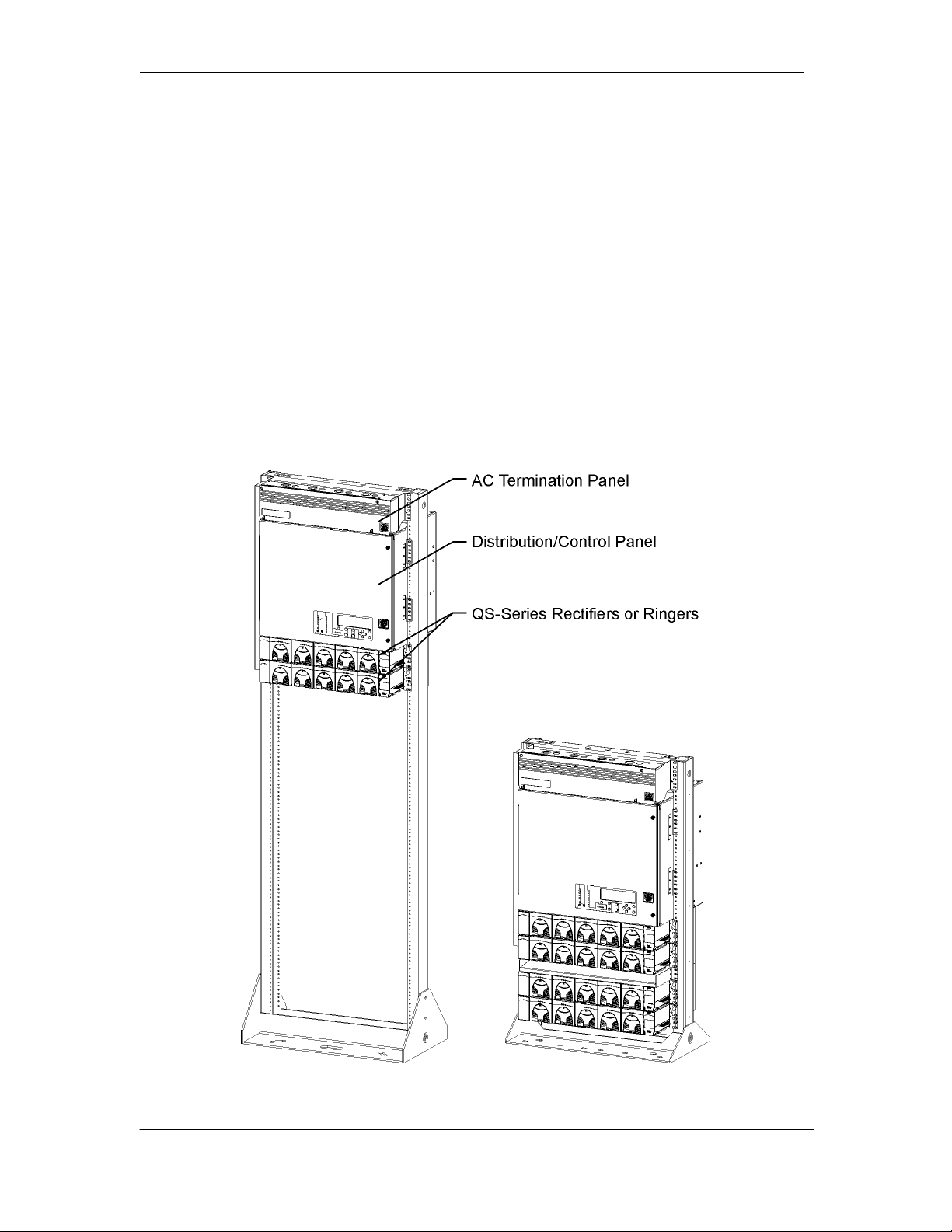
The 48V CPS6000-M2 Power Plant is a 23 inch wide, front access, frame mounted battery plant.
The system integrates QS series vertical airflow rectifiers and ringers, dc distribution options,
battery connections and the Galaxy Millennium II controller in 500A and 1000A capacity
systems. System dimensions are 25.5 inches wide, 15 inches deep and 29.8 inches tall (500A
system) or 38.5 inches tall (1000A system). This allows the system to be mounted in either a 42
inch (1/2 height) frame for mounting on a battery stand or Unigy battery stack or in a 7 foot (full
height) framework with battery trays.
The system operates directly from commercial power in 208/220/240Vac single phase @
50/60Hz. 110Vac operation is also available with some rectifiers. AC connects to a terminal
block panel at the top of the system.
48V CPS6000-M2 DC Power System Configuration
Issue 8 January 2008 7
Page 8
CPS6000-M2 Installation Guide H5694720
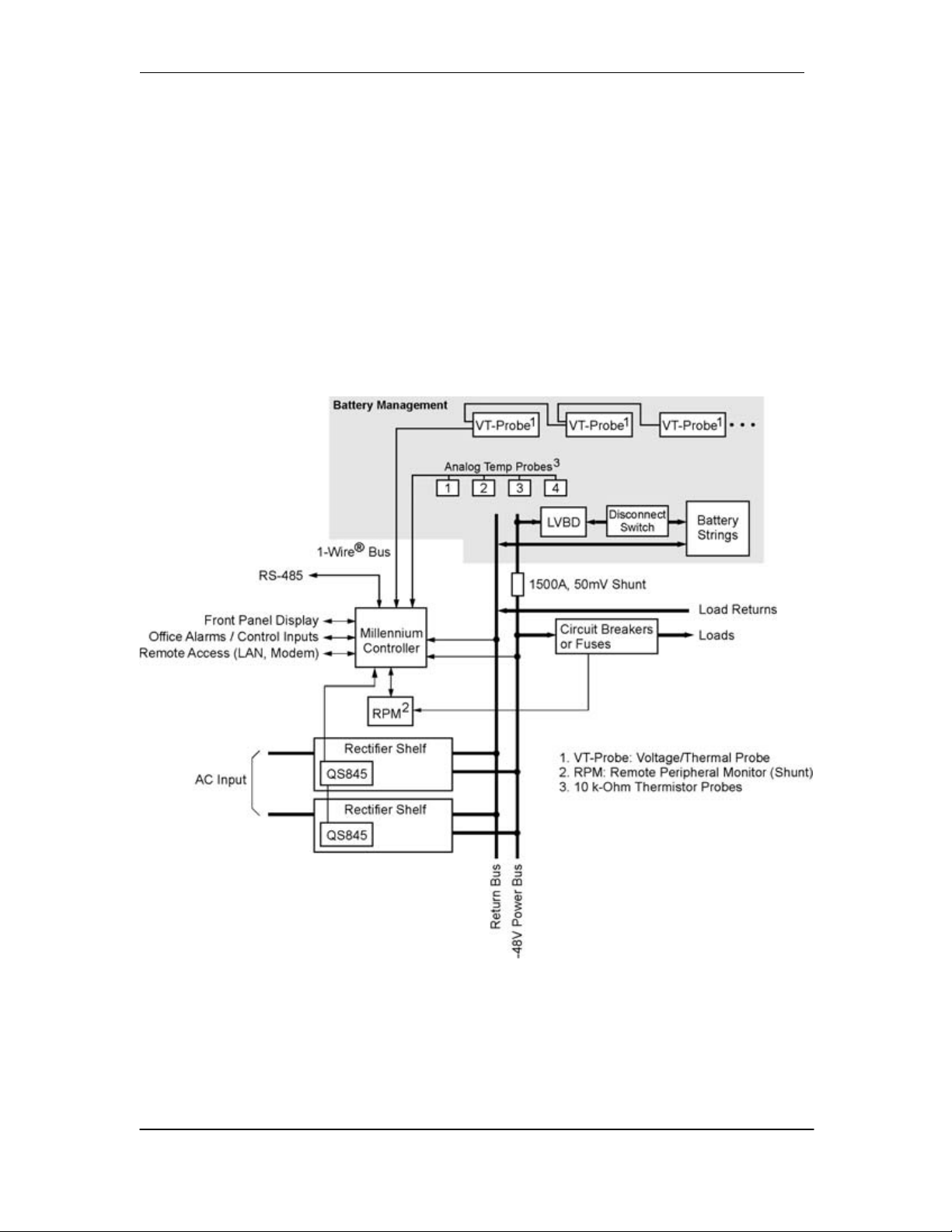
Architecture
The plant architecture is shown in the diagram below. The CPS6000-M2 System rectifiers accept
alternating current (ac) power and produce a regulated dc -48V nominal voltage distributed to
float the batteries, power the controller and power the loads through distribution circuit breakers
or fuses. Batteries are used to provide backup dc power when the ac is lost. They are connected in
parallel with the rectifiers through either optional battery breakers or a low voltage disconnect
(LVD). AC power is distributed to each rectifier through ac terminal blocks located in the ac
termination panel at the top of the frame. The Millennium II system controller monitors and
controls system operation.
CPS6000-M2 Block Diagram
Issue 8 January 2008 8
Page 9
CPS6000-M2 Installation Guide H5694720
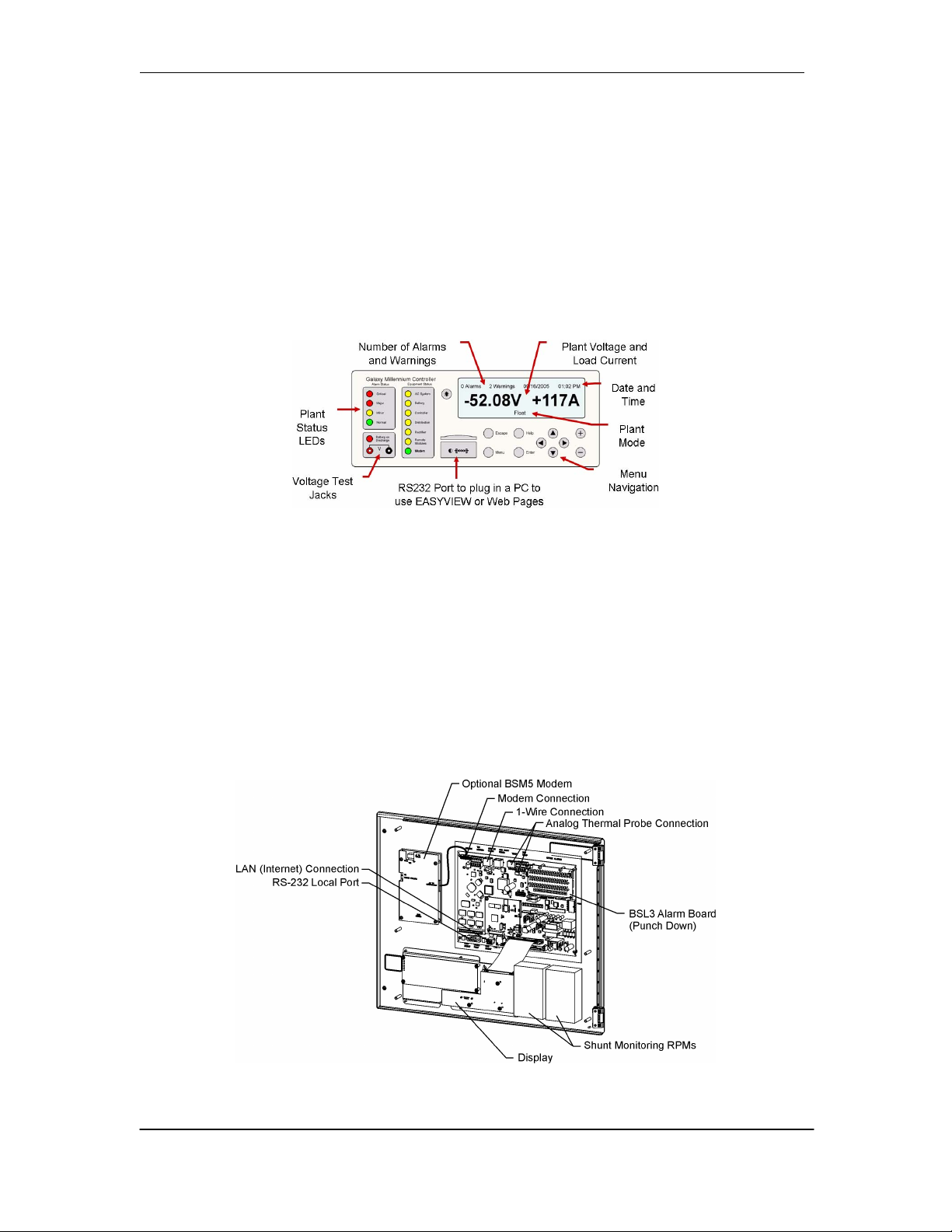
Millennium II Controller
The Millennium II controller is located on the door of the dc distribution. It uses an RS485 bus to
serially monitor and control rectifiers, ringers and peripheral modules called RPM’s. It can also
monitor and control external power equipment, including standby generators, converter plants,
and inverters.
Local viewing and setting of system parameters and various alarm thresholds, user-definable
alarm inputs and relays can be accessed either by a LCD graphics display with intuitive
navigation mounted on the front door of the system or by the local RS-232 port connected to a
notebook computer.
Remote access is available through a 10/100 Base-T network connection to the world wide web
(internet) or your enterprise network (intranet) using standard browsers such as Microsoft Internet
Explorer® or Netscape® Navigator. There is also an optional BSM5 56k bps modem available.
The controller performs various battery management functions to ensure peak performance and
protection from thermal issues. In addition to monitoring for open battery breakers, measuring
current from the battery shunt and monitoring and control of a optional low voltage battery
disconnect contactor, the controller also measures battery string temperature and voltage with
either traditional analog thermistor based temperature probes or digital QS873 Voltage/Thermal
Probes (VT Probes) for slope thermal compensation. The VT probes connect in a daisy-chain
fashion with one probe mounted to the negative post of each mid-string battery using the serial 1Wire® bus.
Issue 8 January 2008 9
Page 10
CPS6000-M2 Installation Guide H5694720
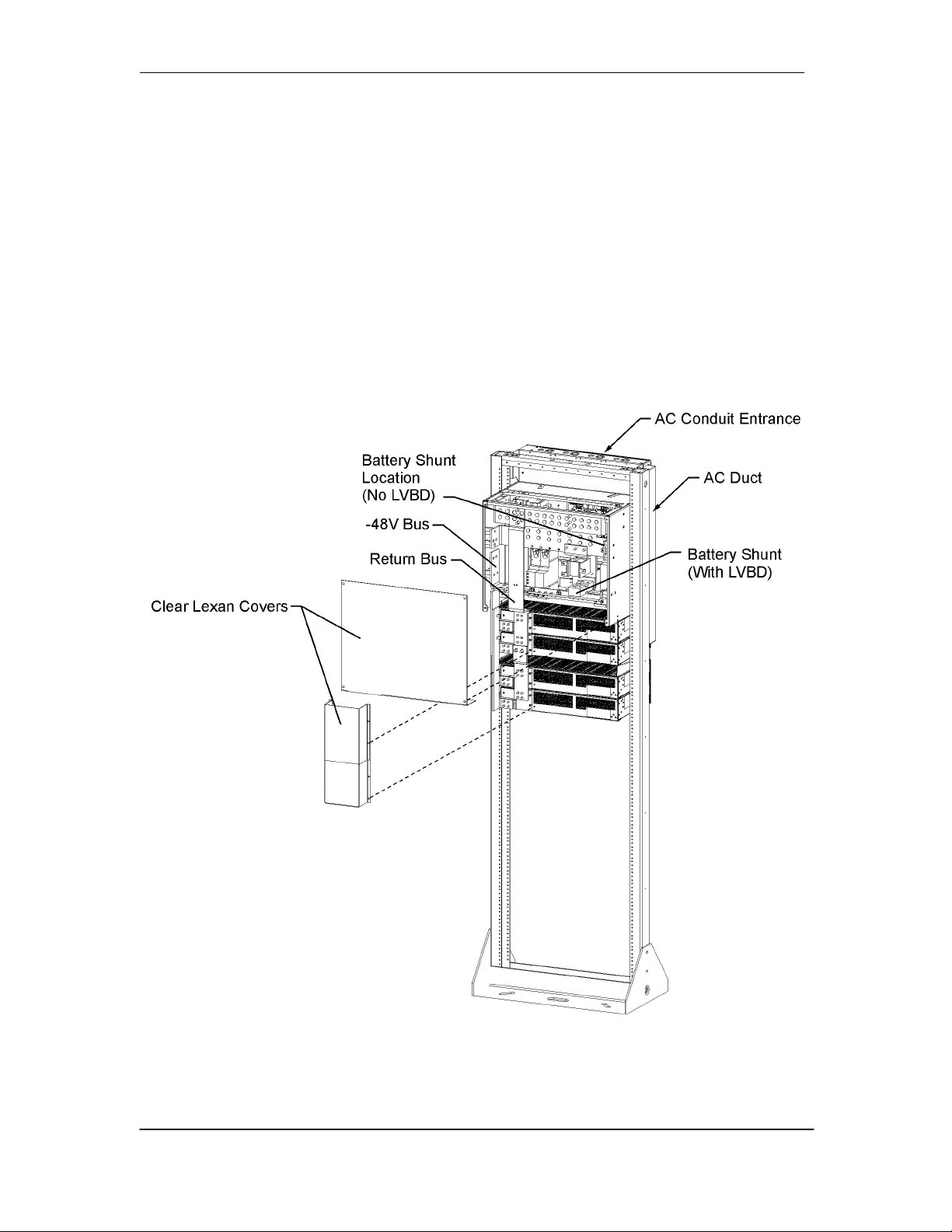
Rectifier Shelves
Rectifier shelves are equipped in either two shelf (500A system) or four shelf (1000A
system) arrangements. DC output from each rectifier is bused up the back to the
distribution and protected by clear lexan covers. Individual AC feeds from terminal
blocks in the ac box route down the ac duct to a connector on each shelf. Serial
communication cables daisy-chain from QS845A interface boards on the left side of each
shelf and up to the controller.
The system is designed to allow field upgrades from two shelf to four shelf systems. This
can be safely accomplished on working systems because the new shelves are first
installed and then bus and cable links added.
DC Bussing to Rectifier Shelves (Rear View)
Issue 8 January 2008 10
Page 11
CPS6000-M2 Installation Guide H5694720
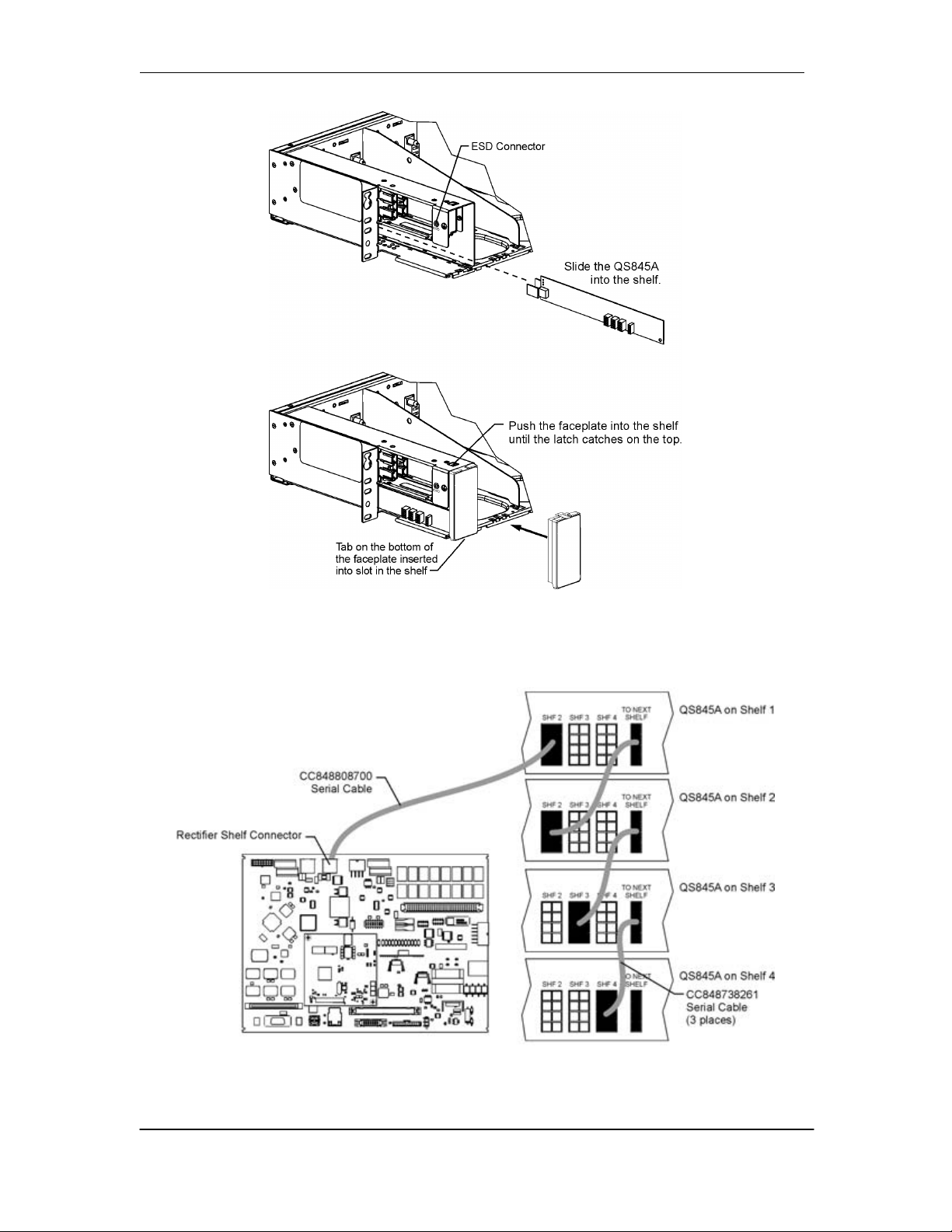
QS845A Rectifier Interface Board Access
Rectifier Communication Connections
Issue 8 January 2008 11
Page 12
CPS6000-M2 Installation Guide H5694720
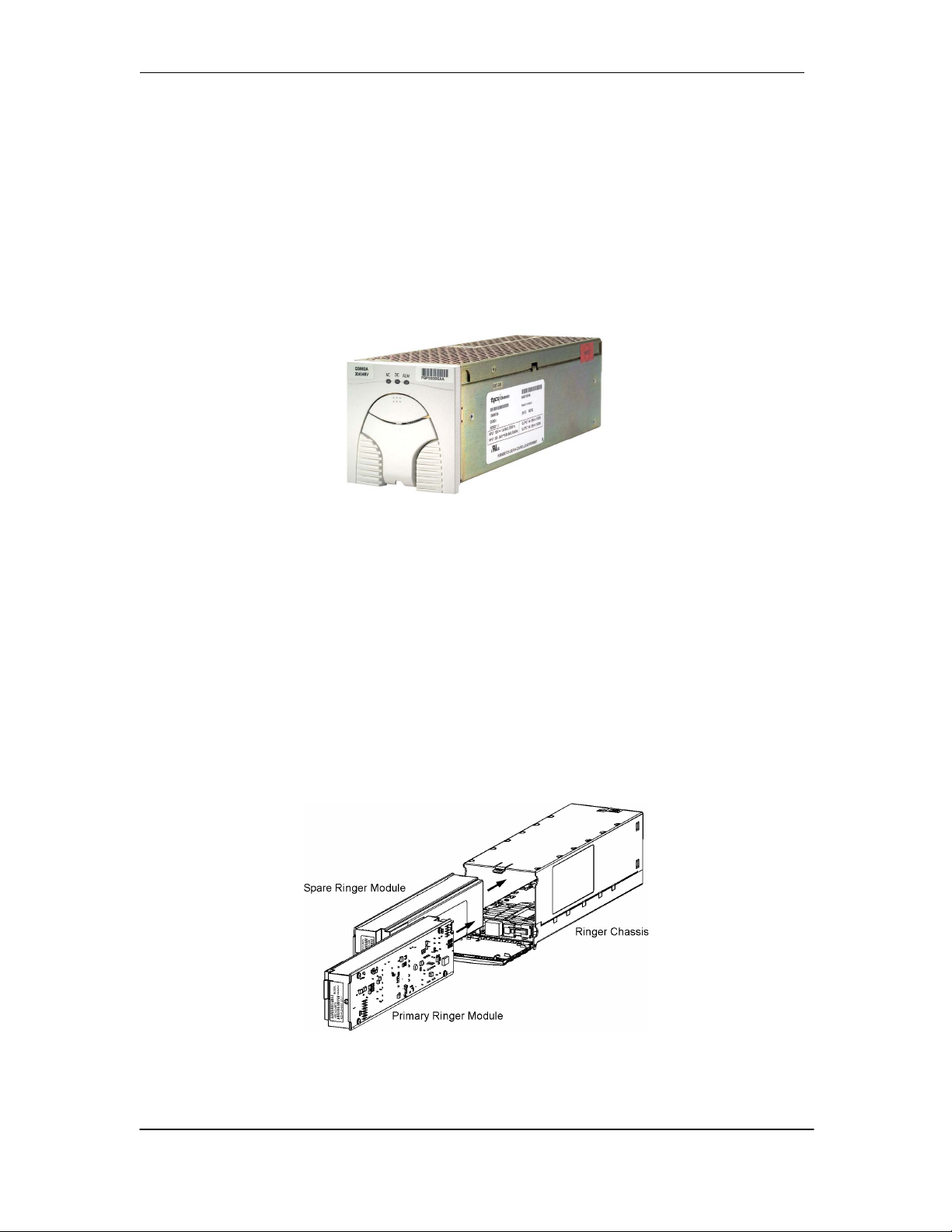
QS-Series Rectifiers
These constant power rectifiers are hot pluggable for quick installation. All interconnections (AC
input, DC output, and control) are made automatically during insertion. The rectifiers
communicate with the controller via a digital RS-485 serial cable allowing all rectifier settings to
be made automatically by the controller. Load-share circuits allow all rectifiers to apportion the
plant load equally, reducing the stress on individual units. The rectifier uses temperature
dependent variable speed fans to provide vertical flow cooling. QS-series of rectifiers are
available in 15A and 25A operating from 85VAC to 275VA and 20A, 30A, 40A, and 50A
operating from 150VAC to 275VAC.
QS-Series Rectifier
QS-Series Ringers
QS820A Ringers convert -48Vdc to a 100VA ringing power output with configurable ac voltage,
ac frequency, and dc offset. A ringer chassis may be installed in the two rightmost positions of
any rectifier shelf. Each ringer chassis includes two vertical airflow fans, accepts up to two
QS820A ringers, a primary and a spare, and provides a single ringing output. Install one ringer
for non-redundant (simplex) operation and two ringers for redundant (duplex) operation. Should
the primary ringer fail or be removed, the ringer output is provided by the spare ringer. The
controller provides ringer output voltage and frequency settings, status and alarm communication.
If communication is lost, the ringers continue to operate with the last received configuration.
QS820A Ringers and QS820M Chassis
Issue 8 January 2008 12
Page 13
CPS6000-M2 Installation Guide H5694720
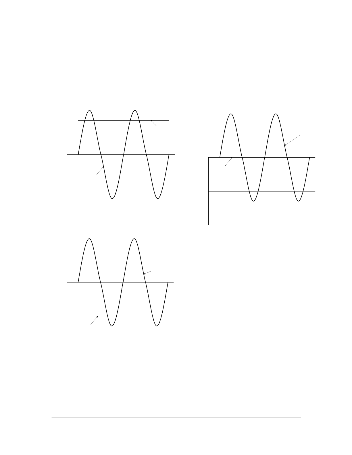
Types of Ringing
QS820 Ringers can be configured to provide one of three types of ringing: Battery Backed,
Ground Backed, and Ground Backed-no dc. Ringing type is selected with jumper J12 on the
chassis and by enabling or disabling dc Offset in the controller
Ground
(VBUS+)
Ring Return
tied to VBUS+
Voltage
(Tip wire)
Ring
(Ring wire)
-48Vdc
(VBUS-)
Ground
(VBUS+)
-48Vdc
(VBUS-)
Voltage
Ring
(Ring wire)
Battery Backed
(Common in USA)
Ring
(Ring wire)
Ground
(VBUS+)
-48Vdc
(VBUS-)
Ring Return
tied to VBUS+
(Tip wire)
Voltage
Ground Backed
No dc
Ring Return
tied to -48Vdc
(Tip wire)
Ground Backed
Ring Signaling Types
Issue 8 January 2008 13
Page 14

CPS6000-M2 Installation Guide H5694720
AC Input
• Connects to AC termination
panel at the top of the
system.
• One 1-inch conduit per
shelf.
• Each rectifier fed
individually by 10 gage wire
protected with a 20A circuit
breaker or fuse.
Battery Options and Monitoring Features
Battery Options
• Designed for operation with Flooded, VRLA,
NiCad, and Lithium batteries (Nickel metal
Hydride in the future).
• Half-height systems mount on Unigy II
batteries, Full Height systems may be
equipped with battery trays.
• Battery trays available for up to 170Ahr
batteries with Anderson PowerPole®
connectors or circuit breaker disconnects.
Battery Monitoring Features
• Open String (OS) Alarms
• Emergency Power Off (EPO) for
disconnecting batteries from the system
• Temperature/voltage probes (up to 16) used in
Battery Management options
Slope Thermal Compensation
Battery High Temp Disconnect
• Battery Discharge Test
• Battery Shunt
Low Voltage Battery Disconnect/Reconnect Contactor (LVBD)
Issue 8 January 2008 14
Page 15

CPS6000-M2 Installation Guide H5694720
DC Distribution and Battery Termination
Group 660 Option
• Two 19 position bullet
distribution panels each
rated at 400A.
• 12 pair of battery landings
for battery cables up to
350Kcmil. (6 pair with
750Kcmil cable) 3/8” studs
on 1” centers
• 8 position center section for
optional 800A Low Voltage
Battery Disconnect
(LVBD), GJ type circuit
breakers with 25mV shunts
or TPL-C fuse blocks with
1500A, 50mV shunts.
Group 661 Option
• One 19 position bullet
distribution panel rated at
400A.
• One fuse panel rated at
600A equipped with 4 TPS
fuses with 100A, 50mV
shunt monitoring and 4
TPL-B fuses with 600A,
50mV shunt monitoring
• RPM shunt monitoring for
fuse panel and up to 4
center TPL-C fuse blocks
with 1500A, 50mV shunt
monitoring
• 12 pair of battery landings
for battery cables up to
350Kcmil. (6 pair with
750Kcmil cable) 3/8” studs
on 1” centers
• 8 position center section for
optional 800A Low Voltage
Battery Disconnect
(LVBD), GJ type circuit
breakers with 25mV shunt
or TPL-C fuse blocks with
1500A, 50mV shunt.
Issue 8 January 2008 15
Page 16
CPS6000-M2 Installation Guide H5694720
Specifications
AC Input
Input Distribution
Wire Size 10 AWG minimum for individual feeds.
System Voltage -48V
Maximum Output Current:
Two Rectifier Shelves (G255) 450A charge, 500A discharge
Four Rectifier Shelves (G256) 800A charge, 1000A discharge
Maximum Recharge Current Installed rectifier capacity minus plant -48V load
Low-Voltage Disconnect 39 to 50 Vdc
Low-Voltage Reconnect 39 to 55 Vdc
Safety Agency Approvals
VDE licensed to VDE0805/EN60950
European Economic Community
(EEC) Directives
Radiated and Conducted
Emissions
Harmonics EN61000-3-2 (IEC61000-3-2)
Voltage Fluctuations EN61000-3-3 (IEC61000-3-3)
Electromagnetic Immunity Meets Telcordia GR-1089-CORE
Electrostatic Discharge EN61000-4-2 Level 3
RF Immunity IEC61000-4-3 Level 3, 10 V/m
EFT IEC61000-4-4 Level 3, No Error; Level 4, No Damage
Surge IEC 61000-4-5 Level 3, No Error; Level 4, No Damage
Conducted Immunity IEC 61000-4-6 Level 3, 10V
Voltage Dips, Interruptions, and
Variations
Operating Ambient Temperature -20 to 45 °C
Altitude -200 to 13,000 feet (-61 to 3962 meters)
Humidity 10% to 95% non-condensing
Audible Noise < 60 dBA
Earthquake Rating Zone 2 or Zone 4, upper floors, depending on battery configuration
Note 1: For altitudes above 5000 feet, derate the temperature by 3.6 °F per 1000 feet. For altitudes above
1524 meters, derate the temperature by 0.656 degrees Celsius per 100 meters.
Terminal Blocks per rectifier fed from 20A breaker or fuse at the AC
service panel.
System Output
Safety / Standards Compliance
Underwriters Laboratories (UL) Listed per Subject Letter 1801: Power
Distribution Center for Communications Equipment, and cUL Certified
(CSA 22.2 950): Safety of Information Technology Equipment
Rectifiers are individually UL Recognized (UL1950), cUL Certified
(CSA 22.2 234) or evaluated to EN60950 by an EC Notified Body, as
appropriate.
EMC Directive 89/336/EEC, Low Voltage Directive 73/23/EEC as
amended by Marking Directive 93/68/EEC
FCC Part 15, Class A
EN55022 (CISPR22), Class A
IEC 61000-4-11
Environmental
See Note 1
Issue 8 January 2008 16
Page 17

CPS6000-M2 Installation Guide H5694720
Installation Category
CPS6000-M2 is suitable for connection to ac utility systems where the expected level of lightning
surges complies with ANSI C62.41 Category B or IEC 60664-1 Overvoltage Category II.
A service entrance surge protector is required in applications where the installation categories can
not be classified as being compliant to either ANSI C62.41 Category B or IEC 60664-1
Overvoltage Category II.
CPS6000-M2 rectifiers have been tested for repeated lightning surges typically found in an
Overvoltage Category III installation; however, a service entrance surge protector is
recommended in cabinet applications to bring the power feeds in compliance to the installation
categories above. The service entrance protection should be coordinated with the protection
provided in the power modules.
The power module provides common-mode protection via a 320V MOV in series with a 2500V
gas-discharge device and differential-mode protection via a 320V MOV in series with a 3.5A fuse
Issue 8 January 2008 17
Page 18
CPS6000-M2 Installation Guide H5694720
Millennium II Controller
General Specifications
Input Voltage Range -48 Vdc (Range: 18-60V)
Maximum Input Power 36W depending upon options
Display Graphic displayed arranged to
8-line by 40-character backlit LCD
Configuration Method Through front panel LCD display and menu keys
Through IBM compatible PC with RS-232 port
Through LAN internet connection
Mounting Requirements Door mounted
Input/Outputs Specifications
Form C Alarm Output Contact Ratings 60VDC at 0.5A
Plant Voltage Measurement
Accuracy
0 to 50 °C (±.05% of full scale + 1
count)
-40 to 85 °C (±0.1% of full scale + 1
count)
Resolution
Plant Current Measurement
Accuracy
Resolution
Temperature Measurement
Accuracy
Thermistor temperature
One-Wire Serial probes
Resolution
4-20mA Input Monitor
Accuracy
Resolution
General (0-5V) Input
Accuracy
Resolution
48V Systems: ±40 mV
48V Systems: ±70 mV
0.01V
0 to +50 °C : ±0.5% of full scale
-40 to +85 °C: ±1.25% of full scale
1A
-5 to +55 °C: ±2°C
-40 to +85 °C: ±3°C
-5 to +55 °C: ±1°C
-40 to +85 °C: ±3°C
0.1°C
±100µA
±10.0µA
0 to +50 °C: ±0.5% of full scale
-40 to +85 °C: ±1.0% of full scale
0.01VDC
Issue 8 January 2008 18
Page 19

CPS6000-M2 Installation Guide H5694720
Rectifiers
Item Specification
Nominal Output Voltage 48/52/54.5 Vdc
Operating Output Voltage
42 to 58 Vdc
Ranges
Boost Voltage 48 to 58 Vdc
Output Current QS861A: 0 to 15A at 54.5V
QS862A: 0 to 30A at 54.5V
QS852A: 0 to 20A at 54.5V
QS853A: 0 to 25A at 54.5V
QS864A: 0 to 40A at 54.5V
QS865A: 0 to 50A at 54.5V
Nominal Input Voltage QS861A: 100/120/208/240
Vac
QS862A: 100/120/208/240
Vac
Input Voltage Ranges QS861A: 85 to 275 Vac
(Shutdown from 135 to
150V)
QS862A: 85 to 275 Vac
QS852A: 208/240 Vac
QS853A: 208/240 Vac
QS864A: 208/240 Vac
QS865A: 208/240 Vac
QS852A: 150 to 275 Vac
QS853A: 150 to 275 Vac
QS864A: 150 to 275 Vac
QS865A: 150 to 275 Vac
(Shutdown from 135 to
150V)
Input Current QS861A: 8A at 120 Vac
4.4A at 208 Vac
QS862A: 13A at 120 Vac
8.8A at 208 Vac
QS852A: 7.4A at 208 Vac
QS853A: 7.4A at 208 Vac
QS864A: 11.8A at 208 Vac
QS865A: 14.5A at 208 Vac
Operating Frequency Range 45 to 66 Hz
Operating Temperature -40 to +65 °C
Output Voltage Regulation ±0.5%
Output Noise, Ripple 250 millivolts peak to peak maximum, over the range dc to
100 MHz
Load Share Accuracy 1.5A maximum deviation between rectifiers
Heat Dissipation at Full Load QS861A: 141W (480 BTU) per rectifier at 120 Vac operation
160W (546 BTU) per rectifier at 240 Vac operation
QS862A: 177W (604 BTU) at 100 to 120 Vac operation
212W (724 BTU) at 200 to 240 Vac operation
QS852A: 133W (454 BTU) per rectifier at 240 Vac operation
QS853A: 151W (515 BTU) per rectifier at 240 Vac operation
QS864A: 240W (819 BTU) per rectifier at 240 Vac operation
QS865A: 267W (911 BTU) per rectifier at 240 Vac operation
Selective High-Voltage
Above 58 Vdc
Shutdown
Backup High-Voltage
Above 60 Vdc for 1 millisecond
Shutdown
Issue 8 January 2008 19
Page 20

CPS6000-M2 Installation Guide H5694720
Ringers
Item Specification
Input Voltage -40 to -57 Vdc See Output VA Thermal Limiting.
Nominal Input Voltage -48 Vdc
Input Current 5 A max.
Output
Voltage
ac tolerance ± 5 Vac
Regulation ±5% ac component only
dc Offset
dc Offset Tracking
Harmonic Distortion 5% THD
Crest Factor 1.21 to 1.51
Output Frequency 15 to 50 Hz
Frequency tolerance ± 1 Hz
Output
VA
Thermal Limiting Output VA may be reduced by reducing Vac when
Load Power Factor Operating: 0.5 Leading to 0.9 Lagging
Operating Temperature -40 to +75 °C See Output VA Thermal Limiting.
Heat Dissipation 50 W (170 BTU / hr)
Under Voltage Shutdown 50% of Output Vac Set Point
ac Component
Type of ringing
Battery Backed
Ground Backed
Ground Backed no-dc
65 to 100 Vac
Factory Default: 100Vac
• -40 to +57 Vdc Battery Backed
• +40 to +57 Vdc Ground Backed
• 0 Vdc Offset Disabled
• dc Offset tracks dc Input Voltage
• Factory Default: Enabled
• Battery or Ground Backed is selected by Ringer
Chassis jumper J12 or by external connection of Ring
Rtn to Battery or to Ground. Factory Default: Battery
Backed by Jumper
± 3 Vdc
Error
Factory Default: 20 Hz
100 VA
operating simultaneously above 50°C and less than
-50Vdc input.
Vac is reduced only sufficiently to prevent damage to the
ringer.
No Damage: 0 Leading to 0.7 Lagging
While shutdown due to external fault, restart will be
performed at approximately 2 minute intervals.
Issue 8 January 2008 20
Page 21

CPS6000-M2 Installation Guide H5694720
3 Safety
Safety Statements
Please read and follow all safety instructions and warnings before installing, maintaining, or
repairing the CPS6000-M2 System:
• The CE Mark demonstrates compliance with the European Union Council Directives for
Low Voltage and EMC.
• The CPS6000-M2 platform is Underwriters Laboratories (UL) Listed per Subject Letter
1801, DC Power Distribution Centers for Telecommunications Equipment.
• CPS6000-M2 shelves equipped with QS820A ringers have hazardous secondary voltages
on the secondary bus output connectors.
• Install only in restricted access areas (dedicated equipment rooms, equipment closets, or the
like) in accordance with articles 110-16, 110-17, and 110-18 of the U.S. National Electric
Code (NEC), ANSI/NFPA No. 70, and pursuant to applicable local codes.
• This equipment is to be used in controlled environments (an area where the humidity is
maintained at levels that cannot cause condensation on the equipment, the contaminating
dust is controlled, and the steady-state ambient temperature is within the range specified).
• This equipment has been evaluated for continuous use in ambient temperature from -40°C
to 65°C.
• This equipment must not be installed over combustible surfaces.
• For installations in the United States, Listed compression connectors are to be used to
terminate Listed field-wired conductors where required. For all installations, the
appropriate connector is to be applied only to the correct size conductor as specified by the
connector manufacturer, using only the connector manufacturer's recommended tooling or
tooling approved for that connector.
• If the proper connector for the country of installation is not provided, obtain appropriate
connectors and follow manufacturer’s and all local requirements for proper connections.
All national and local rules and regulations should be followed when making field
connections.
• The main output voltage (48V) meets SELV requirements.
• Insulation on field-wired conductors should be rated no less than 90° Celsius. Wire
conductor size should be sized per electrical codes for 75° Celsius wire, and based on the
ampacity of the associated protection device. Wiring internal to enclosed equipment
cabinets should be rated at 105° Celsius (minimum).
Issue 8 January 2008 21
Page 22

CPS6000-M2 Installation Guide H5694720
• Torque electrical connections to the values specified on labels or in the product
documentation.
• Battery input cables must be dressed to avoid damage to the conductors (caused by routing
around sharp edges or routing in areas where wires could get pinched) and undue stress on
the connectors.
• Alarm contacts on the office alarm board are not fused; therefore, current limiting
protection for these contacts must be provided by external circuits. Maximum ratings for
alarm connections are 60Vdc and 0.5 amperes. Exceeding these maximum ratings could
result in fire or damage to the unit.
• Fuse and/or circuit breaker loads must not exceed 80% of the fuse and/or circuit breaker
current rating. Distribute loads across the panel.
• The short circuit current capability of the battery input to the distribution panel must not
exceed 10,000A.
• AC branch circuits to this equipment must be protected with either fuses or circuit breakers
sized as required by the National Electric Code (NEC) and/or local codes. The maximum
size of the over-current protector is based on the type of shelf. Refer to the equipment
ratings to assure rating of equipment will not exceed 80% of the value of the protector
chosen.
• High leakage currents are possible due to contribution from simultaneous multiple AC
input connections. Earth ground connection is essential before connecting the ac source to
the shelf. This connection must be achieved by ensuring that the C.O. grounding stud is
connected as shown in the Installation Section, or quality service personnel shall ensure
that the rack system is bonded per the provision below.
• An accessible ac disconnect/protection device to remove power from the equipment in the
event of an emergency must be provided. Disconnect all AC branch circuits prior to making
AC connections.
• Installing fuses or circuit breakers not specified for use in these distribution modules may
result in injury to service personnel or equipment damage. Use only replacement parts
listed in this manual and on the equipment drawings.
• The telecom-type (e.g., GMT type) fuses can produce sparks during interruption or clearing
of a fault on a high energy circuit. Use only fuses provided with safety caps for this type of
circuit. Installing telecom-type fuses not equipped with safety caps may result in injury to
service personnel.
• While installing batteries, follow all safety precautions outlined in the appropriate battery
product manuals.
Issue 8 January 2008 22
Page 23
CPS6000-M2 Installation Guide H5694720
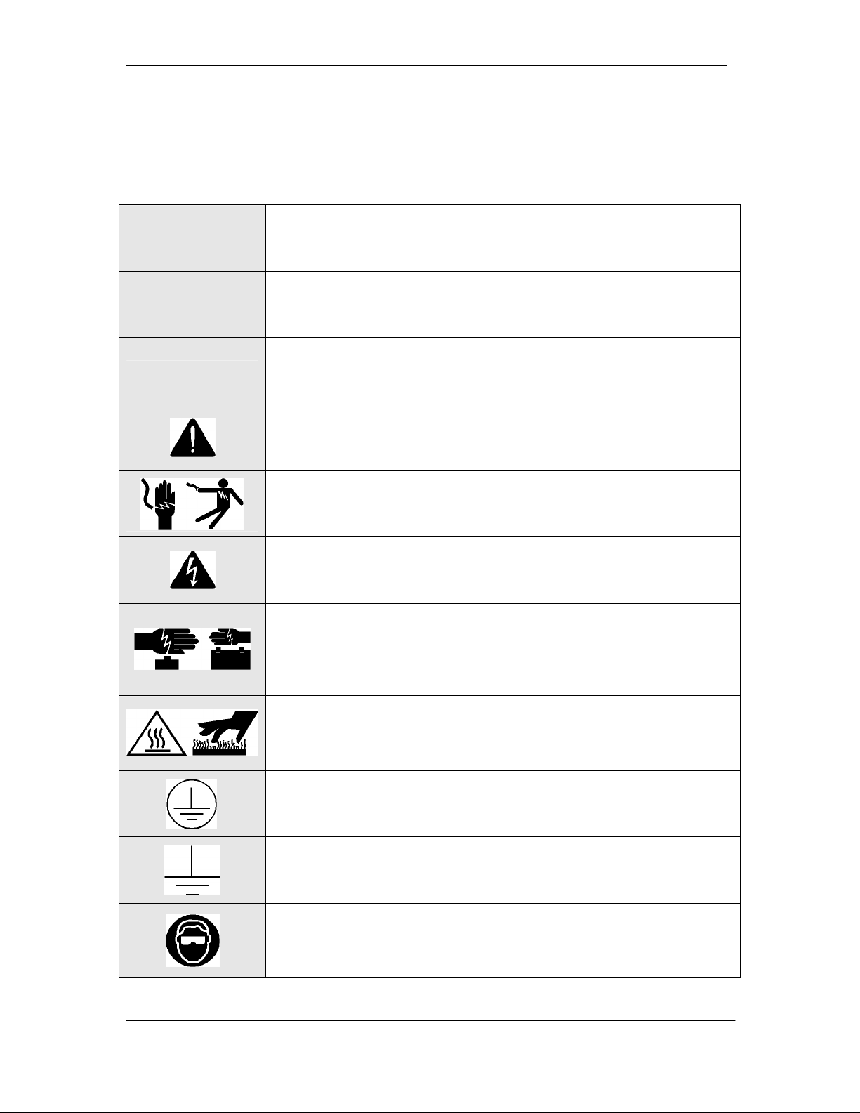
Warning Statements and Safety Symbols
The symbols may sometimes be accompanied by some type of statement; e.g., “Hazardous
voltage/energy inside. Risk of injury. This unit must be accessed only by qualified personnel.”
Signal words as described below may also be used to indicate the level of hazard.
Indicates the presence of a hazard that will cause death or severe personal
DANGER
WARNING
CAUTION
injury if the hazard is not avoided.
Indicates the presence of a hazard that can cause death or severe personal
injury if the hazard is not avoided.
Indicates the presence of a hazard that will or can cause minor personal
injury or property damage if the hazard is not avoided.
This symbol identifies the need to refer to the equipment instructions for
important information.
These symbols (or equivalent) are used to identify the presence of
hazardous ac mains voltage.
This symbol is used to identify the presence of hazardous ac or dc
voltages. It may also be used to warn of hazardous energy levels.
One of these two symbols (or equivalent) may be used to identify the
presence of rectifier and battery voltages. The symbol may sometimes be
accompanied by some type of statement, for example: “Battery voltage
present. Risk of injury due to high current. Avoid contacting conductors
with non-insulated metal objects. Follow safety precautions.”
One of these two symbols may be used to identify the presence of a hot
surface. It may also be accompanied by a statement explaining the hazard.
A symbol like this with a lightning bolt through the hand also means that
the part is or could be at hazardous voltage levels.
This symbol is used to identify the protective safety earth ground for the
equipment.
This symbol is used to identify other bonding points within the
equipment.
This symbol is used to identify the need for safety glasses and may
sometimes be accompanied by some type of statement, for example:
Issue 8 January 2008 23
“Fuses can cause arcing and sparks. Risk of eye injury. Always wear
safety glasses.”
Page 24

CPS6000-M2 Installation Guide H5694720
Precautions
When working on or using this type of equipment, the following precautions should be noted:
• This unit must be installed, serviced, and operated only by skilled and qualified personnel
who have the necessary knowledge and practical experience with electrical equipment and
who understand the hazards that can arise when working on this type of equipment.
• The equipment could be powered by multiple ac inputs. Ensure that the appropriate circuit
protection device for each ac input being serviced is disconnected before servicing the
equipment. Do not disconnect permanent bonding provisions unless all ac inputs are
disconnected.
• High leakage currents may be possible on this type of equipment. Make sure the equipment
is properly safety earth grounded before connecting power.
• Batteries may be connected in parallel with the output of the rectifiers. Turning off the
rectifiers will not necessarily remove power from the bus. Make sure the battery power is
also disconnected and/or follow safety procedures while working on any equipment that
contains hazardous energy/voltage.
• Hazardous energy and voltages are present in the unit and on the interface cables that can
shock or cause serious injury. Follow all safety warnings and practices when servicing this
equipment. When equipped with ringer modules, hazardous voltages will be present on the
ringer output connectors.
In addition to proper job training and safety procedures, the following are some basic precautions
that should always be used:
• Use only properly insulated tools.
• Remove all metallic objects (key chains, glasses, rings, watches, or other jewelry).
• Wear safety glasses. Fuses can produce sparks. High energy levels on buses and
distribution components can produce severe arcing.
• Test circuits before touching.
• Lock out and tag circuit breakers/fuses when possible to prevent accidental turn on.
• Be aware of potential hazards before servicing equipment.
• Identify exposed hazardous electrical potentials on connectors, wiring, etc. (note the
condition of these circuits, especially wiring).
• Use care when removing or replacing covers; avoid contacting circuits.
Issue 8 January 2008 24
Page 25

CPS6000-M2 Installation Guide H5694720
Handling Batteries
• To direct attention to the possible source of danger from battery gases, post one or more
warning signs, lettered in large characters, in a conspicuous location near the battery. For
example:
• Fully brief anyone who is permitted access to battery areas on the hazards of handling lead-
acid batteries. Make it clear to anyone handling, unpacking, or installing lead-acid batteries
that they contain electrolyte (sulfuric acid and water). Everyone must wear protective
equipment such as rubber gloves, rubber aprons, full face mask, and splash-proof goggles
when performing any activity involving handling of batteries or cells containing electrolyte.
• A storage battery gives no indication by its appearance of the potential energy stored in it.
All lead-acid storage cells/batteries have enormous short circuit capability which can result
in serious burns. Use extreme care to avoid shorting out cell and/or battery terminals.
Shorting a cell or battery with a non insulated tool can vaporize or throw the tool.
• All lead-acid batteries generate hydrogen gas, even under open circuit conditions. If not
permitted to escape, this gas can build up to explosive concentrations. NEVER tamper with
or block the vent caps of the 12IR125 battery modules. A damaged gas vent cap could
become clogged, resulting in an explosion due to internal pressure. Such an explosion could
short circuit other battery modules and result in a fire. ALWAYS place batteries in a wellventilated area. NEVER place battery modules in a sealed environment.
• In case of electrolyte contact with the skin, remove the electrolyte immediately by flushing
the affected area with large amounts of plain tap water. In case of electrolyte in the eye,
pour water into the inner corner of the eye and allow at least one quart of water to run over
the eye and under the eyelid. Eye injuries should be treated by a physician immediately.
Issue 8 January 2008 25
Page 26

CPS6000-M2 Installation Guide H5694720
Special Installation Notes
Deutsch
• Installationsanleitung
• Eingangsspannung ( Voltage ) : 120/200-240VAC , DC 54VDC
Eingangsstrom ( Current ) : <15A per rectifier, DC 15A-1000A
Eingangsleistung ( Watts ) :
Nennfrequenz ( Frequency ) : 50 / 60 Hz
• Seriennummer ( Assembly No. ): J5694720
• Modellnummer (Modell No. ) : H5694720
• Abmessungen sind nur zur Referenz : 978mm x 648mm x 381mm
( Dimensions are for reference only )
• Max. Umgebungstemperatur : max. 45 deg. C
( Max. Operation temperatur )
• Achtung: Für kontinuierlichen Feuerschutz sollte die Sicherung nur mit einer des
gleichen Types ersetzt werden.
Sicherungswert :
( Warning : For continued protection against fire replace with same type and rating of
fuse )
• Das System ist ein Gerät der Schutzklasse I / Überspannungs Kategorie II
( Power Supply is a Class I equipment / overvlotage category II )
• Ausgangsspannungen und -stöme: DC 58 V / SELV
( Output Voltage and Current )
• --Das Gerät darf nur in Räumen mit beschränktem Zutritt aufgestellt werden.
( Nur ausgebildetes Personal )
• --Nur für Aufstellung auf Boden oder einer anderen brennbaren Oberfläche
geeignet.
• --Das Gerät hat keinen eigenen Ausschalter, es muß daher mit einem Ein- und
Ausschalter im Versorgungskreis versehen sein.
• --Das Gerät ist für den Einbau in IT- Geräte in einem Rahmen bestimmt (siehe weitere
Anleitung)
• --Beim Einbau des Gerätes ist daraf zu achten das alle Anforderungen gemäß EN60950
eingehalten werden.
ACHTUNG: HOHER ABLEITSTROM
VOR ANSCHLUSS AN DEN VERSORGUNGSSTROMKREIS
UNBEDINGT ERDUNGSVERBINDUNG HERSTELLEN
Issue 8 January 2008 26
Page 27

CPS6000-M2 Installation Guide H5694720
Espanol
Notas especiales para instalaciones en países de habla hispana
• Instrucciones de instalación (Installation Instructions)
• Voltaje (Voltage): 120/200-240VAC
• Corriente (Current): <15A per rectifier
Frecuencia (Frequency): 50/60Hz
• Voltaje y corriente de salida (Output Voltage and Current): 54VDC, 15A-1000A
Temperatura máxima de operación (Maximum Operation Temperature):
45°C (113°F)
• Sin cabina contra incendios, suelo no combustible
(No fire enclosure, non-combustible floor)
• Evaluado en EN60950
(Evaluated to EN60950)
Issue 8 January 2008 27
Page 28

CPS6000-M2 Installation Guide H5694720
4 Installation
This section describes the following installation sequence for the CPS6000-M2 power system.
1. Preparations
2. Anchoring frame
3. Connecting frame ground
4. Connecting CO ground
5. Connecting ac utility
6. Installing batteries
7. Wiring dc loads and installing fuses/circuit breakers
8. Installing rectifiers and converters
9. Controller Connections
10. Starting Up System
Preparation
Safety
Please review all safety warnings in Section 3 before beginning the installation process. Observe
all warnings and labels on the equipment.
WARNING: Due to the possibility of working on energized circuits during these
procedures, all tools and test equipment must be insulated in an approved manner.
Proper ESD protection is required in order to prevent ESD damage to the
equipment.
WARNING: Only qualified personnel should install and service the power
system and plug-in modules. Hazardous energy and voltages are present in the
unit and on the interface cables and will shock or cause serious injury or death if
safety precautions are ignored. Follow all safety warnings and practices when
servicing this equipment.
Issue 8 January 2008 28
Page 29

CPS6000-M2 Installation Guide H5694720
Wiring Guidelines
• All electrical connections should be made using the proper crimping tools and dies and
should be torqued to values specified.
• All building wiring should comply with the NEC and other applicable local codes.
• The temperature rating of the wire must be 90°C minimum.. Wire gauge must be sized based
on 75°C wire and the ampacity of the associated branch-circuit protection.
• Wiring internal to enclosed equipment cabinets must be rated no less than 105° Celsius.
Packaging
• All packages should be opened with a box cutter with the blade minimally exposed so that
only the sealing tape is cut.
• Save all packaging material until the system has been powered up and all parts are operating
within specifications.
Installation Tools
You will need the following tools to install and test the CPS6000-M2 System.
• Wire cutters and strippers
• Heat shrink gun
• 5/16-inch (8 mm) hex driver
• Digital meter with an accuracy of
±0.02%
• Screw drivers (flat-blade and Phillips)
• ESD wrist strap
• 48V test load
• Calibrated clamp-on dc current meter
(0.1 ADC sensitivity)
• Torque wrench
• Socket wrenches:
− 7/16” and 9/16” for load and
battery connections;
− 19 mm for anchor bolts;
− 12" extension for socket
• Masonry drill kit as required
• Compression for installation of various
compression lugs
• Protective canvas
• Insulating rubber mat
• Standard insulated installation tools,
screwdrivers, etc.
• Windows-based personal computer
laptop (PC) and cable to connect the PC
communications port to the local port of
the controller OR a CAT5 LAN cable.
Issue 8 January 2008 29
Page 30

CPS6000-M2 Installation Guide H5694720
Accounting for Ship Loose Materials
QTY H5694720 Group COMCODE DESCRIPTION
60 660, 661 802841635 Flat Washer, 3/8
60 660, 661 801829607 Lock Washer, 3/8
60 660, 661 841064777 Nut Hex, 3/8
40 660, 661 230707-1 Amp Barrel Terminal
144 660, 661 901352617 Nut ¼ - 20
3 441, 451, 471 406954222 Cable ties for securing battery cables
1 441, 451, 471 CC848809104 2 gauge battery cable
2 440-471 901281444 Phillips flat head screws 10-32 x 3/8
3 440-471 848466884 Battery separators
1 440, 441, 451, 471 CC848768201 Front battery bracket
1 441, 451, 471 CC848770248 Clear cover for battery breaker
2 441, 451, 471 845143858 Screw 6-32 x ¼
2 101-104 CC408575947 ¼-20 x ¾-inch HH bolt
2 101-104 801829557 ¼-inch lockwasher
2 101-104 CC408576012 ¼-inch flat washer
1 104 CC848795385 Drill template
Torque Requirements
Torque (in-lb) Connection
10 AC terminal block screws
35 10-32 screw for dc rear covers and ac duct
35 12-24 frame-mounting screws
65 1/4-20 nuts for bullet panel loads
135 M8 bolts for large breaker and fuse kits and LVBD connections
240 3/8-16 nuts for large breaker and fuse load leads and all battery leads
Issue 8 January 2008 30
Page 31

CPS6000-M2 Installation Guide H5694720
Anchoring Frame
Floor Mounted Frames
Using the 847135688 Floor Anchor Kit (recommended):
Anchor Type (Hilti) Wrench Hole Size Torque
(4) 12 mm Cap Bolts 19 mm
Note: For systems with tray mounted batteries at sites requiring Seismic Zone 4 rating, (2)
847135688 kits are required to provide (8) floor anchors.
Note: If using Equivalent Floor Anchors, make sure the floor anchors are rated for this
application.
18mm
100mm deep
Step Action
Mark floor anchor locations, using the provided Floor Template.
720 in·lbs
60 ft·lbs
81.6 N·m
1
G103 7ft Standard Frames
G104 7ft Heavy Duty Frames
Drill anchor holes.
2
Caution: Follow safe floor drilling procedures to prevent possible asbestos exposure.
Place frame and install floor anchors according to manufacturer requirements.
3
Issue 8 January 2008 31
Page 32

CPS6000-M2 Installation Guide H5694720
Battery or Battery Stand Mounted Half-Height Frames:
Step Action
Place and secure frame to battery or battery stand per instructions provided with the
battery stand or adapter.
1
Connecting Frame Ground
Select a Frame Ground landing on the top of the frame and clean.
Step Action
Secure Frame Ground connection with
provided hardware:
(2) 801256165 ¼-20 x 3/4" HH bolt
(2) 801829557 ¼-inch lockwasher
(2) 802841577 ¼-inch flat washer
1
If required by local code or practice,
treat with an oxidation inhibitor such as
NO-OX.
Use 7/16” socket. Torque to 65 in·lbs.
Note: Landings are compatible with lugs
with 5/8” hole spacing for ¼” or 6mm
hardware.
Issue 8 January 2008 32
Page 33

CPS6000-M2 Installation Guide H5694720
Battery or Battery Stand Mounted Frames:
If required by local code or practice, battery or battery stand mounted frames may be grounded to
the frame or chassis of the other equipment. Select a Frame Ground landing at the side of the
frame and clean.
Step Action
Secure Frame Ground connection with
provided hardware:
(2) 801256165 ¼-20 x 3/4" HH bolt
(2) 801829557 ¼-inch lockwasher
(2) 802841577 ¼-inch flat washer
1
If required by local code or practice,
treat with an oxidation inhibitor such as
NO-OX.
Use 7/16” socket. Torque to 65 in·lbs.
Note: Landings are compatible with lugs
with 5/8” hole spacing for ¼” or
6mm hardware.
Connecting Central Office Ground (COG)
Action
• COG lead landing is as shown.
• If required by local code or practice,
treat with an oxidation inhibitor such
as NO-OX.
• Secure COG connection with provided
hardware:
(2) 841064777 3/8-16 nut
(2) 801829607 3/8-inch lockwasher
(2) 814251898 3/8-inch flat washer
• Use 9/16” socket. Torque to 240 in·lbs.
Note: Landings are compatible with lugs with
1” hole spacing for 3/8” hardware.
Issue 8 January 2008 33
Page 34

CPS6000-M2 Installation Guide H5694720
Connecting AC Utility
WARNING: Disconnect all AC branch circuits prior to making AC connections
to the CPS6000 Plant System. When connecting to utility source, ensure
compliance to all local and national wiring rules.
Step Action
• AC is connected to terminal blocks located at the top of the equipment frame.
• Route and attach conduit or other commercial fitting. A 1-inch conduit is required per
rectifier shelf.
1
• Pull and terminate AC wire.
• Terminal blocks are provided for up to twenty rectifiers (four shelves).
2
• Each rectifier must be fed by 10 gauge wire protected by a 20A circuit breaker or
fuse.
• Terminate ground connection on terminal blocks or optional lugs.
Issue 8 January 2008 34
Page 35

CPS6000-M2 Installation Guide H5694720
Installing Batteries
Installing Battery Trays
Optional battery trays are suitable for use with general trade VRLA batteries. VRLA batteries
come in two jar widths; approximately 4.25” width, typically used in 19” frame applications and
approximately 5” width, typically used in 23” frame applications. These battery trays
accommodate both types.
Step Action
Position the battery tray in the frame as
shown. Secure with provided (Comcode
1
901078717) rack screws.
Installing Tray Mounted Batteries
The system can be configured with battery trays sized for various batteries and may include
optional factory installed battery disconnect or battery mid-string voltage and temperature
monitoring units.
WARNING: All batteries contain hazardous electrical energy. Lead-acid
batteries contain sulfuric acid and explosive hydrogen gas. Follow all precautions
noted in the literature accompanying the batteries. Use only insulated tools.
CAUTION: Equipment frame anchoring, load rating, and seismic zone rating
should be verified before field installing trays and batteries.
Issue 8 January 2008 35
Page 36

CPS6000-M2 Installation Guide H5694720
Typical Battery Installation on Trays with Battery Disconnect
Step Action
Ensure disconnect switch is in
the OFF position (downward)
prior to making any
connections.
1
Remove the two 6/32 screws to
remove the plastic cover.
Does system have larger batteries?
Yes – Proceed to Step 2. No – Go to Step 3.
Reposition the battery
disconnect switch to the
outside of the battery tray as
shown using (2) provided
2
901281444 Flathead 10-32 x
3/8” Phillip screws.
Issue 8 January 2008 36
Page 37

CPS6000-M2 Installation Guide H5694720
Step Action
Place front bracket on battery
tray. Batteries sit on flange of
bracket holding it in place.
3
Note: For systems with larger
batteries the front bracket is
mounted to extend beyond the
front of the tray.
Connect one end of the 2 gage
cable to the input bus of the
disconnect switch. Secure with
4
1/4-20 hex nuts (901352617)
provided.
Torque to 65 in-lb.
Re-attach clear plastic cover to
disconnect switch and secure
5
with 6-32 screws.
Place four batteries on each
battery tray.
6
Position three Battery Spacers
between the batteries.
Interconnect three inter-cell bus
bars to configure one 48V
battery string per the battery
7
manufacturer’s instructions.
Issue 8 January 2008 37
Page 38

CPS6000-M2 Installation Guide H5694720
Step Action
Attach the battery securing top
rail. Secure with provided
8
(Comcode 901078717) rack
screws
Connect the 2 gage cable
between the V- post of the leftmost battery and the input bus
9
of the disconnect switch.
Torque to battery
manufacturer’s specification.
Is the system equipped with a factory installed QS873 VT thermal probe?
Note: The Millennium II can support up to 16 QS873VT 1-Wire probes. It also
has the capability of directly monitoring up to (4) analog temperature probes.
Temperature measurements are also available through the use of Remote
Peripheral Modules (RPM’s).
Connect the QS873 VT thermal
probe to the inter-cell busbar at
the V- post in the middle of the
battery string.
Cable-tie to front bracket along
10
with the battery cable.
See “Installing Thermal Probes”
later in this chapter if field
installing Thermal Probes
No – Proceed to Step 11. Yes – Proceed to Step 10.
Issue 8 January 2008 38
Page 39

CPS6000-M2 Installation Guide H5694720
Step
11
Action
Connect the factory-wired battery
cable to the V+ post of the rightmost battery. Torque to battery
manufacturer’s specification.
Battery installation is complete.
Attaching Battery Cables to CPS6000-M2 Busses
• Battery Cable landings are as shown. If
required by local code or practice, treat
with an oxidation inhibitor such as
NO-OX.
• Secure Battery Cable connections with
provided hardware (per cable):
(2) 841064777 3/8-16 nut
(2) 801829607 3/8-inch lockwasher
(2) 814251898 3/8-inch flat washer
• Use 9/16” socket. Torque to 240 in·lbs.
Action
Note: Landings are compatible with lugs with
1” hole spacing for 3/8” hardware.
Issue 8 January 2008 39
Page 40

CPS6000-M2 Installation Guide H5694720
Installing and Wiring DC Loads
Installing DC Bullet Style Distribution
Bullet Terminal distribution panels accept Bullet Terminal Circuit Breakers, TPS Fuse Holders,
and GMT Fuse Modules.
CAUTION: Ensure Circuit Breakers are in the OFF position prior to installation. Ensure
Fuse Holders are empty prior to installation.
• CAUTION: In order to meet UL Listing temperature limits, GMT Fuses on the bullet fuse
module must meet these layout restrictions:
• All 12A rated fuses must have an unused position to at least one side.
• All 15A rated fuses must not be installed next to another fuse. Leave empty position.
• CAUTION: In order to meet UL Listing temperature limits, bullet distribution panels
must meet the following layout restrictions
• Panel is rated 400A but derates to 350A if Large Breakers or Fuses are installed in the
Center Section of distribution.
• bullet circuit breakers rated 80A, 90A and 100A require one adjacent position be left
unoccupied.
Step Action
Loosen screws and swing hinged retainer cover clear of the distribution devices (if
present).
1
Vertical distribution panel
Insert distribution devices into the panel load busses as shown in the figure above.
2
Connect loads.
3
Note: To allow for future growth start from the top most position and work down the
panel. This will allow orderly and managed cable dressing as loads are added.
Issue 8 January 2008 40
Page 41

CPS6000-M2 Installation Guide H5694720
Step Action
Secure GMT Module Return bus bars to the distribution panel Return bus bar with
4
provided (901352617) 1/4-20 nuts.
Secure the hinged retainer cover if removed in step 1 above.
5
Single- and Two-Pole, Breakers and TPS Fuses:
Secure Two-Pole adapter busses to the distribution Load and Return busses with
6
provided (901352617) 1/4-20 nuts.
Secure Load and Return Cable connections with provided (901352617) 1/4-20 nuts.
7
Use 7/16” socket. Torque to 65 in·lbs.
Verify (using a voltmeter) polarity of the voltage between the Return bus and the
8
distribution input bus.
Verify wiring polarity at the input of the load equipment.
9
Leave breaker switches in the OFF position and do not install load fuses until the load
equipment is ready to be energized.
• WARNING: Do not install load fuses until the load equipment is ready to be energized.
Three-Pole Breakers:
Secure Three-Pole adapter busses to the distribution Load and Return busses with
10
provided (901352617) 1/4-20 nuts.
Use 7/16” socket. Torque to 65 in·lbs.
Secure Load Cable connections with provided hardware (per cable):
(2) 841064777 3/8-16 nut
11
(2) 801829607 3/8-inch lockwasher
(2) 814251898 3/8-inch flat washer
Use 9/16” socket. Torque to 240 in·lbs.
12
13
Using a voltmeter, verify polarity of the voltage between the Return bus and the
distribution input bus.
Verify wiring polarity at the input of the load equipment.
Leave breaker switches in the OFF position until the load equipment is ready to be
energized.
• WARNING: Do not install circuit breakers until the load equipment is ready to be
energized.
GMT Bullet Fuse Modules:
14
15
16
17
Issue 8 January 2008 41
Strip load wire 3/8” and secure in the GMT module terminal block.
Use #1 slot screwdriver. Torque to 13 in·lbs.
Dress and wire tie with service loop to provide strain relief.
Using a voltmeter, verify polarity of the voltage between the RTN and distribution input
bus.
Verify wiring polarity at the input of the load equipment.
• WARNING: Do not install load fuses until the load equipment is ready to be energized.
Page 42

CPS6000-M2 Installation Guide H5694720
Installing TPL-C Fuse Holders and Panels
TPL-C Fuse holders can either be factory or field installed per kit CC109129129128. The
following figure shows the installation of this kit and corresponding fuse installation. Note that
the fuse snaps into the fuse handle which is then pushed into the holder.
Step Action
Ensure Fuse Holders are empty prior to making any connections.
1
Secure Load Cable connections with provided hardware (per cable):
(2) 841064777 3/8-16 nut
(2) 801829607 3/8-inch lockwasher
2
(2) 814251898 3/8-inch flat washer
Use 9/16” socket. Torque to 240 in·lbs.
WARNING: Do not install load fuses until the load equipment is ready to be energized.
Issue 8 January 2008 42
Page 43

CPS6000-M2 Installation Guide H5694720
Installing Large Circuit Breakers
KS22012 Circuit Breakers can either be factory installed or field installed per the following kits:
• CC109127635 150A Single Pole Breaker
• CC109127627 250A Single Pole Breaker
• CC109127486 Two Pole Breaker
Step Action
Ensure Circuit Breakers are in the OFF (down) position prior to making any
connections.
1
Issue 8 January 2008 43
Page 44

CPS6000-M2 Installation Guide H5694720
Installing QS-Series Rectifiers
Action
Rectifiers are installed or removed with the rectifier handle in the open position as shown.
Use the above rectifier installation procedure as needed in the following steps:
Step Action
Turn on ac service circuit breakers to apply power to the system rectifier positions.
1
Install a rectifier in an available rectifier position.
2
Wait until the rectifier establishes communications with the controller (the red Fail
3
LED stops flashing).
Verify green Norm LED is lit.
4
Issue 8 January 2008 44
Page 45

CPS6000-M2 Installation Guide H5694720
Step Action
Apply 10 amperes of load to the system.
5
If equipped, verify the contactor closes and connects the battery strings.
6
If an audible alarm is present, press the ENTER key to MUTE the audible alarm.
7
Verify all LEDs are green on the controller and the display is visible with the proper
8
voltage shown.
Increase the plant load current to 20 amperes.
9
10
11
12
13
14
15
16
17
18
19
Install rectifier in the next position.
Wait until the rectifier establishes communications with the controller (the red Fail
LED stops flashing).
Verify green Norm LED is lit.
Verify the two rectifiers are present and verify the rectifier output currents by using the
front panel:
MENU > STATUS > RECTIFIERS > RECTIFIER CURRENTS.
Increase the plant load current to 50 amperes.
Continue to add rectifiers until the system is fully equipped or has a maximum of 20
rectifiers.
Verify the rectifiers share the load and the voltage regulation is correct. Rectifiers
should load share after 2 minutes to within 2% of the total average output.
Verify front panel display voltage is within 0.5% of the Float Set-point.
Remove a rectifier and ignore the request to remove missing equipment.
Verify the controller identifies the rectifier as missing to verify that the Minor
Communication Fail alarm is operational.
20
For more information on QS Rectifiers, see the Troubleshooting section.
Re-install the rectifier and verify that the alarm clears.
Issue 8 January 2008 45
Page 46

CPS6000-M2 Installation Guide H5694720
Installing QS-Series Ringers
Step Action
• Up to two Ringer Chassis’s may be installed per rectifier shelf, one in each of the two
right-most power slots. Each Ringer chassis accepts up to two ringer modules, a
primary and a spare.
• For redundant ringing, install both Primary and Spare Ringers in each Ringer Chassis.
WARNING: Consider the Ring signal as hazardous voltage. When
1
rectifiers and/or battery power is present, all installed QS820M ringer
chassis and QS820A ringer modules will be powered.
• Note: Ringer output connections are made after ringers are seated in the Ringer
chassis.
• Note: The primary and spare Ringer modules install facing opposite directions. No
rectifiers may be installed to the right of a Ringer Chassis. Slots dedicated to Ringers
do not require an ac input circuit in the AC Termination Panel
• Slide the ringer chassis into
the power slot.
• Press firmly until the
connector on the rear of the
ringer chassis engages with
the connector at the back of
the power slot on the shelf.
• Verify the hook under the
front left of the ringer chassis
2
hooks under the shelf.
• Press down on the faceplate
latch and open the faceplate.
• Secure the ringer chassis to
the shelf using one #4 screw,
hand tight to approximately 5
in-lbs.
• Repeat if a second ringer
chassis is required.
Issue 8 January 2008 46
Page 47

CPS6000-M2 Installation Guide H5694720
Step Action
• Locate connector on rear of
ringer module and the mating
connector on the inside rear of
the ringer chassis.
• Align the ringer module
connector with the ringer
chassis connector. Place the
ringer module in the guides
3
4
and slide the ringer in until it
fully engages with the
connector at the back of the
ringer chassis.
• Note: The Ringer modules
install facing opposite
directions
• Repeat until all Ringer
modules are installed.
• Use Tip Jumper J12 to set the Ringer output type.
• Note: Ringer output type is determined by connecting Ring Return (Tip) to Battery or
Ground. External connection of Ring Return (TIP) to Battery or Ground may be used
with J12 in EXTERNAL position. Ringer output is disabled if Ring Return is not
connected to Battery or to ground.
Ringing Type
Ground Backed 1. TIP BAT
Battery Backed 2. TIP GND
Ground Backed – no-dc 2. TIP GND
Externally Selected 3. EXTERNAL
Tip Jumper
J12 Position
Comments
Also requires Controller
configuration of dc Offset: Disabled
Requires external connection of Tip
to Battery or Ground.
Repeat until all Ringer modules are installed
Issue 8 January 2008 47
Page 48

CPS6000-M2 Installation Guide H5694720
Step Action
• Connect Ringer loads using Molex 39-01-4031 connector, Socket Terminal to the
HDR13 plug located inside the Ringer Chassis at the bottom-front
WARNING: Consider the Ring signal as hazardous voltage.
5
Controller Connections
Issue 8 January 2008 48
Page 49

CPS6000-M2 Installation Guide H5694720
The MCR1/MCR1B control board contains the connections for all the input and outputs. The
following table provides a list of the connections with their respective reference designators and
brief description of the particular connection.
Interface
Reference Description
P1
P2
P3
P6
P7
P8
P9
P13
P14
P15
P201
P202
P205
TB1
TB2
J10
Connectorized interface for large parallel format 8x40 LCD assembly
10/100 Base-T LAN/Ethernet interface
Connectorized interface for 10K/30K thermistor probe options or 210E
Connectorized input for input power, monitoring of two shunts, plant sense voltage,
and Major Fuse alarm (Same connection as on the Millennium)
RJ45 receptacle for ground referenced Auxiliary RS485 circuit and One-Wire
monitoring devices
BSL1-4 circuit pack Interface connector for Input/Output to controller
RJ45 receptacle for isolated RS485 system component monitoring and control of
rectifiers, converters, low voltage disconnect contactors, and bay level alarm inputs
(Serial Rectifier bus)
Factory test connector (not used in the field)
Connectorized interface for future smaller serial format LCD
Connectorized interface for future smaller serial format LCD
Connectorized interface for optional Modem
Ground referenced DB-9 for local RS232 serial port
Option board connector
Terminal block interface for RS232/RS485 Auxiliary port and Remote Peripheral
Module (RPM) connections
Terminal block interface for three additional 10K thermistor probe or 210E connection
options
USB interface (reserved for future use)
Fuses
Two Fuses, located on the MCR1/MCR1B board, provide protection for the controller input
power and Alarm Battery Supply (ABS). ABS is used to power alarm panels or other devices
requiring the power system voltage at no more than 1.3A.
Fuse Description Fuse Size
F1 Controller Input Power 3A
F2 Alarm Battery Supply (ABS) 1.3A
Issue 8 January 2008 49
Page 50

CPS6000-M2 Installation Guide H5694720
Network (LAN) Connections
Step Action
Note
1
2
3
The LAN port P2 is an IEEE 802.3 compliant 10/100Base-T Ethernet interface.
This port can be used for remote monitoring or configured as local Craft port.
Factory default is to be a DHCP client where the network will serve the controller
and IP address.
Since the cable length required to connect to the network is variable, this cable must
be supplied by the user.
At the controller, connect one end of the network interface cable to P2. This
connector is located at the bottom center of the MCR1 board, and immediately
below the MCR2 board.
Connect the other end to an IEEE 802.3 compatible network.
Configure the network parameters by contacting the customer’s network
administrator.
BSL Alarm Outputs and Control Inputs
The following tables provide the input/output signal assignments for the BSL alarm interface
board. Use 18-26 gage wire for alarm board terminations. Form-C Alarm contact ratings are
60VDC, 0.3A
Issue 8 January 2008 50
Page 51

CPS6000-M2 Installation Guide H5694720
BSL Alarm Outputs
Signal Name Pin
Power Critical
Alarm -Audio
Power Critical
Alarm -Visual
Power Critical
Alarm-External
Power Major
Alarm-Audio
Power Major
Alarm –External
Power Major
Alarm–Visual
Power Minor
Alarm-Audio
Power Minor
Alarm –Visual
Power Minor
Alarm –External
Major Fuse Alarm
Number
1 PCRAO 34 MNFR
2 PCRAC 35 MNFC
3 PCRAR
4 PCRVR 37 BDO
5 PCRVC 38 BDC
6 PCRVO
7 PCREO 40 ACFR
8 PCREC 41 ACFC
9 PCRER
10 PMJAR 43 RFAO
11 PMJAC 44 RFAC
12 PMJAO
13 PMJEO 46 HVR
14 PMJEC 47 HVC
15 PMJER
16 PMJVR 49 UR1O
17 PMJVC 50 UR1C
18 PMJVO
19 PMNAO 52 CTLRR
20 PMNAC 53 CTLRC
21 PMNAR
22 PMNVR 55 UR2O
23 PMNVC 56 UR2C
24 PMNVO
28 PMNER 58 VLVR
29 PMNEC 59 VLVC
30 PMNEO
31 MJFO
32 MJFC
33 MJFR
Signal
Reference
Signal Name Pin Number Signal
Minor Fuse Alarm
36 MNFO
Battery On
Discharge Alarm
AC Fail Alarm
Rectifier Fail
Alarm
High Voltage
Alarm
User Relay 1
Controller Fail
Alarm
User Relay 2
Very Low Voltage
39 BDR
42 ACFO
45 RFAR
48 HVO
51 UR1R
54 CTLRO
57 UR2R
60 VLVO
Reference
Issue 8 January 2008 51
Page 52

CPS6000-M2 Installation Guide H5694720
BSL Alarm and Control Inputs
Alarm Pin
Number
61 LVD2 Low Voltage 2 Disconnect State Detect
62 LVD2R
Fuse Alarm Major 63 FAJ
Fuse Alarm Minor 65 FAN
Auxiliary Alarm Major 64 AMJ
Auxiliary Alarm Minor 66 AMN
Timer Float Control 67 TFLT
Timer Boost Control 68 TBST
Timer Control Return 69 TRTN
Plant Battery Test
Open String Detect 72 OS
Transfer Rectifier 1 73 TR1
General Purpose Input 4 74 IN-4 (previously TEQ)
General Purpose Input -5 (Previously
Engine Transfer)
Reserve Operation
Transfer Rectifier 2 79 TR2
Transfer Rectifier 4 80 TR4
Reserve Battery-Emergency Power Off 81 RBRPO
General Purpose Input 1 82 IN-1
BTP or General Purpose Input 2 83 IN-2/BTP
Low Voltage 1 Disconnect State Detect 84 LVD1
Transfer Rectifier 3 85 TR3
General Purpose 4-20mA Measuring
Circuit
General Purpose 4-20mA Measuring
Circuit-RTN
BTPFLT or Generic Input 3 89 IN-3/ BTPFLT
Low Voltage 3 Disconnect State Detect
Also Battery Thermal Protect Major
General Purpose 0-5Vdc Measuring
Circuit
General Purpose 0-5Vdc Measuring
Circuit-RTN
70 PBTR
71 PBT
75 IN-5 (Previously ETR)
77 RO
78 ROR
87 4-20mA
88 4-20mAR
90 LVD3/ BTMJ
91 0-5V
92 0-5VR
Signal Name
Issue 8 January 2008 52
Page 53

CPS6000-M2 Installation Guide H5694720
Following are additional details concerning the alarm and control input signals.
BSL-63 FAJ: Fuse Alarm Major
An optional “battery” or non-grounded potential input, must use an external 1K ohm 2W current
limiting resistor at the source. A Fuse Alarm Major is generated when battery potential is
received.
BSL-65 FAN: Fuse Alarm Minor
An optional “battery” or non-grounded potential input, must use an external 1K ohm 2W current
limiting resistor at the source. A Fuse Alarm Minor is generated when battery potential is
received.
BSL-72 OS: Open String Alarm
An optional “battery” or non-grounded potential input, must use an external 1K ohm 2W current
limiting resistor at the source. This circuit is used to signal the controller that a battery string
protective device or switch is in the open position. An Open String Alarm is generated when
battery potential is received.
BSL-64 AMJ: Aux Major
An optional “battery” or non-grounded potential input, must use an external 1K ohm 2W current
limiting resistor at the source. This circuit is used to allow the controller to monitor another
power device and provide alarms for it. An Aux Major Alarm is generated when battery potential
is received.
BSL-66 AMN: Aux Minor
An optional “battery” or non-grounded potential input, must use an external 1K ohm 2W current
limiting resistor at the source. This circuit is used to allow the controller to monitor another
power device and provide alarms for it. An Aux Minor Alarm is generated when battery potential
is received.
LVD1: BSL-84 Low Voltage Disconnect Active
An optional “battery” or non-grounded potential input, must use an external 1K ohm 2W current
limiting resistor at the source if not using standard
controller. This circuit is used to inform the controller that the monitoring circuit of a Low
Voltage Disconnect device has failed.
LVD2/LVD2R: BSL-61/62 Low Voltage Disconnect Active
A closure between these points or a ground signal into LVD2/ BSL-61 is used to inform the
controller that a Low Voltage Disconnect device has opened.
External Boost Option
A variety of external devices may be used to initiate boost in the controller. Wiring is required
from positions 67/68/69 on the BSL board for operation of this feature. Providing a contact
closure between TBST and TRTN initiates the boost feature. A contact closure between TFLT
and TRTN returns the plant to float.
Rectifier Sequence Option
The controller is capable of sequencing rectifiers on line after detecting AC is being provided by
emergency generator. Internal Rectifier Sequencing requires external wiring to ETR/ETRR on
BSL pin numbers 75/76, and optionally RO/ROR on BSL pin numbers 77/78, in order to
Lineage Power LVD circuit boards or
Issue 8 January 2008 53
Page 54

CPS6000-M2 Installation Guide H5694720
function. The controller can also accept ground signals onto TR1 to TR4 on BSL 73/79/ 85/80
from an external device to control the sequencing of plant rectifiers in groups as follows:
TR leads and Associated Rectifiers
TR
Signal
TR1 G01, G02, G09, G10, G17, G18, G25, G26, G33, G34, G41, G42, G49, G50, G57,
G58
TR2 G03, G04, G11, G12, G19, G20, G27, G28, G35, G36, G43, G44, G51, G52, G59,
G60
TR3 G05, G06, G13, G14, G21, G22, G29, G30, G37, G38, G45, G46, G53, G54, G61,
G62
TR4 G07, G08, G15, G16, G23, G24, G31, G32, G39, G40, G47, G48, G55, G56, G63,
G64
Rectifiers Affected
Alarm Battery Supply Outputs on BSL Board
ABS Pin Numbers
Signal
Name
ABS 93
ABS 94
DG 95
DG 96
BSL-93, 94 ABS: Alarm Battery Supply
This is an alternate plant voltage source for user alarm systems. This power is fused with a 1-1/3
ampere ABS fuse labeled F2 on the controller.
BSL-95, 96 DG: Discharge Ground
Plant ground/return source for user alarm systems.
Pin No.
Issue 8 January 2008 54
Page 55

CPS6000-M2 Installation Guide H5694720
Installing Optional Circuit Packs
Field-Installable Circuit Packs
BSM5 Modem Card
Step Action
Note
Note
Installation or replacement of this pack can be done “hot”; power removal is not
necessary.
Remove the controller plastic front cover.
1
Place insulator under BSM5 modem and install to the door using four 407882141
2
standoffs. Wrap insulator around modem and secure with four 845143866 screws.
Connect 848091798 cable assembly between the BSM5 J100 plug and P201 on the
3
MCR1 board.
Note: This step may be performed at a later time
4
Connect a telephone cable to the RJ11 connector at the top of the BSM5 board
OR
Connect Tip/Ring conductors to TB1 at the top of the board.
NOTE: Tip is TB1 pin 1 (Pin closest to the RJ11 connector) and Ring is Pin 3. Pin 2
is not used.
Operate the controller reset switch on the MCR1 board in the lower left corner of the
5
MCR1 board.
The Password Reset button is to the LEFT of the serial port connector (Not present on
the MCR1B must use the front panel), and the Controller Reset is to the right of the
serial connector.
Issue 8 January 2008 55
Page 56

CPS6000-M2 Installation Guide H5694720
BSW Data Switch Card
Step Action
Note
Note
Installation or replacement of this pack can be done “hot”; power removal is not
necessary.
Install two 407882133 standoffs on the MCR1 located just below TB1 connector in the
1
upper left hand corner.
Place BSW pack inside the 847950938 insulator.
2
Plug BSW pack into the P205 connector on the MCR1 board
3
Secure the BSW board to the standoffs with two 900562208 screws.
4
To install the Data Switch Extension board, please see the Basic Installation And
User’s Guide For The Millennium II Controller (167-792-181).
BSL Alarm Termination Board
An insulation displacement (punch down) type alarm terminal board (BSL3, 848741711) is
provided with the system. For a wire wrap type terminal board, order BSL4 (848749507) and
perform the following steps:
Step Action
In the upper right hand corner of the MCR1 board, find the alarm board already
1
installed.
Remove the two screws holding the board at the top.
2
Holding the board on both sides, slowly, but firmly, remove the alarm board from the
3
P8 connector.
Connect the new alarm board to P8 and press down firmly, until the board is seated.
4
Secure the alarm board at the top using the two screws removed earlier.
5
Issue 8 January 2008 56
Page 57

CPS6000-M2 Installation Guide H5694720
Remote Peripheral Monitoring (RPM)
Monitoring modules available consist of:
• 221F -50-150mV Shunt monitors (6 channels + 1 temperature channel)
• 221J 0-100mV DC Voltage transducer monitors (6 channels + 1 temperature channel)
• 221A 0-3V DC Voltage monitors (6 channels + 1 temperature channel)
• 221B 0-16V DC Voltage monitors (6 channels + 1 temperature channel)
• 221C 0-70V DC Voltage monitors (6 channels + 1 temperature channel)
• 221D 0-200V DC Voltage monitors (6 channels + 1 temperature channel)
• 222A Binary Input monitor (6 channels + 1 temperature channel)
• 223T Temperature monitor (7 Channels)
• 214A Control Relay module (3 sets of programmable form C relay outputs)
The user may connect a maximum of 95 of any combination of these modules serially.
Step Action
NOTE:
1
This section only describes a single module connection to the controller. Modules
MUST BE PROGRAMMED after they have been installed or they may not function
properly. Detailed connection and configuration information may be found in the
RPM Product Manual 167-790-063.
Using RPM bus cable (comcode 407377704), wrap the cable through the EMI
inductor bead twice. Place the bead approximately 3 inches from the controller.
Connect the bus cable to TB-1 on Millennium and TB101 on the RPM
TB-1 Pin
Assignments
6 *6 Blue or White Power/Communications
8 *8 Blue or White Power/Communications
9 or 10 FGND Bare wire Shield
*connections of the bus wire are NOT polarity sensitive.
TB-1 Pin
Descriptions
RPM
Conductor
Color
RPM Conductor
Description
Issue 8 January 2008 57
Page 58

CPS6000-M2 Installation Guide H5694720
Step Action
2
3
4
5
6
7
Note
8
Secure the module connection unit and route the wires through the open-faced
bottom of the connection unit.
Make the connections to TB2 on the connection unit:
TB-2 Pin RPM Conductor
Color
IN Blue or White Power/Communications
OUT Blue or White Power/Communications
SHIELD Bare wire Shield
*connections of the bus wire are NOT polarity sensitive.
* there are 2 IN, and 2 OUT connections. Either one may be used.
Locate the control unit. This is the half with circuitry on it.
Each RPM must have a unique switch address to be recognized by the controller. In
the lower right hand side of the control unit (inside), are two rotary switches. Set
SW-1 (LO) to 1. The module will be recognized as 01 by the controller. Other
modules added cannot have the same address or 00 for the address.
Carefully attach the control unit to the connection unit using the ribbon connector.
This connector/cable is not keyed, so be careful to line up the pins properly.
After approximately 1 minute, the green LED on the front of the module will blink
once approximately every 5 seconds.
RPM Conductor
Description
Issue 8 January 2008 58
Page 59

CPS6000-M2 Installation Guide H5694720
Thermal
Without thermal probes, many of the controller’s battery management features will not function,
or will produce erroneous results. Some features requiring thermal inputs are:
• Slope Thermal Compensation
• Reserve Time Prediction
• High Temperature Alarm
• High Temperature Disconnect
The controller supports both analog and digital thermal probe inputs. Analog signal probes
connect to the controller at the P3 temperature probe connector or TB2 terminal block. The first
thermal probe connects to P3 and three more probes may be connected to TB2 by cutting of the
connector. If more than four thermal probes are required, a 210E Thermal Probe Multiplexer can
be connected to the P3 connector for an additional 8 probes. The 210E monitors the probe
temperatures and reports the highest temperature to the controller. See Section 8 for thermal
probes and cable options. See Product Manual 157-010-202 (Thermal Probe Multiplexer) for
ordering and installation of a 210E and associated cables.
Probes
TB2 Pin Description
1 Probe 2
2 Probe 2 RTN
3 Probe 3
4 Probe 3 RTN
5 Probe 4
6 Probe 4 RTN
There are also QS873 VT 1-Wire thermal probes that use the P7 1-Wire connector on the
controller.
Issue 8 January 2008 59
Page 60

CPS6000-M2 Installation Guide H5694720
Issue 8 January 2008 60
Page 61

CPS6000-M2 Installation Guide H5694720
Analog Thermal Probe Cables
Issue 8 January 2008 61
Page 62

CPS6000-M2 Installation Guide H5694720
Installing QS873 VT Battery Probes
Step Action
Insert the RJ-45 end of the CC848817024 wireset into the P7 1-wire connector on the
1
controller.
Cut the brown voltage sense wire on the CC848817024 at the 3-pin connector.
2
QS873 probe provides 2-pin
and 3-pin receptacles and a 1/4inch ring terminal.
3
Insert the 3-pin connector end
into the receptacle on the
closest VT-Probe.
Snap the cover closed on the VT-probe.
4
Place the first probe to the battery post (as in the battery string picture above).
5
Verify the number of probes (1) registered with the controller with command:
6
MENU →STATUS → BATTERIES → NUM TEMP PROBES.
Connect either the 848719803 (5-ft) or the 848719811 (10-ft) cable to the 2-position
7
receptacle of the first probe and to the 3-position receptacle of another probe.
Verify the number of probes (2) registered with the controller with command:
8
MENU → STATUS → BATTERIES →NUM TEMP PROBES.
Repeat Steps 7-8 for each probe until all probes are installed.
9
When all probes are installed, verify they are connected and operating with command:
10
MENU → STATUS → BATTERIES → NUM TEMP PROBES.
The controller is now set to make thermal measurements in performing slope thermal
compensation. Additional parameters may be set on the controller to customize this feature.
Issue 8 January 2008 62
Page 63

CPS6000-M2 Installation Guide H5694720
5 Controller User Interface
The Millennium II controller monitors and controls system components rectifiers, converters,
distribution modules, and Remote Peripheral Modules (RPMs) via a digital communications bus.
It can also monitor and control external power equipment, including standby generators,
converter plants, and inverters.
System parameters, various alarm thresholds, user-definable alarm inputs and relays can be
viewed and configured from the controller display, or from a laptop computer connected to a
local RS-232 or Ethernet port, or by remote access is through a network connection to the world
wide web (internet) or your enterprise network (intranet). An optional 56k modem is also
available.
NOTE: A complete list of Controller Alarm Descriptions and Troubleshooting instructions can
be found in Section 7.
Millennium II Front Panel Main Display
Menu Navigation Buttons
Issue 8 January 2008 63
Page 64

CPS6000-M2 Installation Guide H5694720
Display Contrast
Millennium II Main Display and Menus
Parameter Change
Direction Buttons
Enter Button
Menu Button
ESC Button
Help Button
Lamp Test
In the Main Display, the ▲▼ buttons increase or decrease
the display contrast.
When changing a system parameter, the ▲▼ buttons
increase or decrease the value of the parameter.
In the Menus, the ◄▲▼► direction buttons navigate to
make a selection
Enters a sub-menu or confirms a parameter change. From
the Home Page only, goes to the top level Main menu.
Goes to the top level Main menu.
Goes up one menu level or exits a parameter change without
saving.
Shows a Help screen.
Initiates a Lamp Test operation.
Main Display
The Main Display is the normal controller
display. The display will return to the Main
Display after a period of inactivity.
Top Level Menu
Information Menus
Control / Operations Menu
The Main menu allows you to view your
equipment status in detail, history, and to view
and edit a variety of parameters.
These Information menus give detailed
information regarding the status and history of
your plant.
The Control / Operations menu allows you to
perform common operations on your plant.
Operations that are required to turn up and
verify your plant are detailed in the Installation
and Test and Verification sections of this
manual.
Issue 8 January 2008 64
Page 65

CPS6000-M2 Installation Guide H5694720
Configuration Menu
CAUTION: Incorrect plant settings can result in hazardous conditions and
equipment damage or injury. Make sure all plant settings are suitable for
your application, batteries, and other equipment.
The Configuration menu allows you to access
and modify all user accessible plant parameters.
Configuration tasks that are required to turn up
and verify your plant are detailed in the
Installation and Test and Verification sections
of this manual.
NOTE: An Hourglass may appear in the lower
left hand corner of the screen. This indicates
that a configuration change is being saved to
non-volatile memory.
Issue 8 January 2008 65
Page 66

CPS6000-M2 Installation Guide H5694720
Millennium II Controller Status and Alarms
Alarm Status LEDs
Status Function Condition
Note: Which conditions are indicated as Critical, Major, and Minor Alarms may be configured by
the user.
Normal
Critical Alarm
Major Alarm
Minor Alarm
Battery on
Discharge
Remote
Access
[LAN/Modem]
Normal operation, no alarms, inputs and outputs are in
their normal range.
Power to load equipment is at immediate and high risk.
Power to load equipment is at immediate risk.
A problem requiring attention exists, but power to load
equipment is not at immediate risk.
Batteries are discharging and delivering current to the
load.
Blinks to indicate traffic on an attached LAN or
Modem.
Equipment Status LEDs
Status Function Condition
AC System
Battery
Controller
Rectifier/Converter
Distribution
Remote Modules
Remote Access
[LAN/Modem]
AC input to one or more rectifiers is out of range.
The batteries are not in a normal operating state.
The system controller has detected an internal
problem.
A rectifier or converter power unit in the system has
failed
The output distribution is not in a normal operating
state.
There is a problem with a Remote Peripheral
Module (RPM)
Blinks to indicate traffic on an attached LAN or
Modem.
Audible Alarm
The controller assembly is equipped with a user configurable alarm
buzzer.
Voltage Test Jacks
Voltage Test Jacks allow you to measure the main plant output voltage
with a hand-held meter.
Issue 8 January 2008 66
Page 67

CPS6000-M2 Installation Guide H5694720
Local and Remote Access Ports
Local Access
Remote Access
Examples of Frequently Used Menu Features:
This section contains a small number of menu navigation examples to help you get familiar with
the menu.
The examples below use shorthand to describe the navigation process. For example, “MENU →
CONTROL / OPERATIONS → START LAMP TEST” means:
Step Action
Connect a laptop PC to a RS-232 port or Ethernet port and access the
controller with EasyView or Web Pages.
An RJ-45 Ethernet connector is provided for 10/100 Base-T network
connection to the world wide web (internet) or your enterprise network
(intranet) using Microsoft Internet Explorer®, Mozilla Firefox®, or other web
browser. An optional 56k modem is also available.
1
Press to go to the top level Menu.
2
Press navigation buttons to select Control / Operations.
3
Press to select and enter Control / Operations.
4
Press navigation buttons to select Start Lamp Test.
5
Press to execute the Start Lamp Test command.
Lamp Test: MENU > CONTROL / OPERATIONS > START LAMP TEST
Lamp Test allows you to make sure all LEDs and displays in your system are working. This test
lights up all of the LEDs and displays in the system for about ten seconds. Multicolor LEDs light
up multiple colors in sequence, and should be lit for the entire length of the test.
Control / Operations
Start Lamp Test
Restart Devices
Clear Events
Using the Lamp Test feature is a quick and easy way to see if a system component is
communicating with the system controller. If it responds to Lamp Test, then it is receiving
commands from the controller.
Issue 8 January 2008 67
Page 68

CPS6000-M2 Installation Guide H5694720
Clear Events: MENU > CONTROL / OPERATIONS > CLEAR EVENTS
Latched events may be cleared using this feature. Latched events remain active after their cause
is removed (retired) until manually cleared.
Control / Operations
Start Lamp Test
Restart Devices
Clear Events
If the Alarm is a Latched Event and does not retire after performing this operation, the alarm
condition most likely still exists.
Uninstall Devices: MENU > CONTROL / OPERATIONS > UNINSTALL
EQUIPMENT
This command can be used to clear a COMMUNICATION Fail alarm that has been caused by
removing installed equipment (rectifiers, converters, distribution monitors, thermal probes,
batteries monitors).
Control / Operations
Start Lamp Test
Restart Devices
Clear Events
Uninstall Equipment
Alarm Cutoff
This feature is used to silence local audible alarms. Any subsequent Power Critical, Power
Major, or Power Minor alarm will again sound the audible alarm.
When the alarm occurs, the “CUT OFF AUDIBLE ALARM” appears. Press ENTER to turn
off alarms. Then “TURN ON AUDIBLE ALARM” message appears to turn audible alarms
back on.
Issue 8 January 2008 68
Page 69

CPS6000-M2 Installation Guide H5694720
View Rectifier Current: Menu→ Status→ Rectifiers→ Rectifier Currents
This command is used to view rectifier currents.
Status
Rectifiers
Alarm Thresholds
Rectifier
Currents
View IP Address: Menu→ Status→ Network Settings→ (Port #)→ IP Address
This command is used to view the controller’s network IP address.
Status
Rectifiers
Network Settings
Port 1 or 2
IP Address
Restart Rectifiers: Menu → Control / Operations → Restart Rectifiers
This command is used to restart rectifiers.
Control /
Start Lamp Test
Restart Devices
Clear Events
Restart
Rectifiers
This is a non-invasive procedure: rectifiers and converters that are operating normally ignore this
command.
Alarm History: Menu → History → Alarm History
This command is used to view alarm history.
History
Alarm History
Rectifier History
Issue 8 January 2008 69
Page 70

CPS6000-M2 Installation Guide H5694720
Controller Display Menu Maps
Configuration Menu Map
*Note: The QS series of constant power rectifiers do not utilize the current limit threshold setting
(30-110%) under Rectifier configuration. QS series rectifiers are designed to provide 100% their
nameplate power rating at any given normal output condition and will ignore this configuration.
Issue 8 January 2008 70
Page 71

CPS6000-M2 Installation Guide H5694720
Control and Operations Menu Map
Issue 8 January 2008 71
Page 72

CPS6000-M2 Installation Guide H5694720
Status Menu Map
Issue 8 January 2008 72
Page 73

CPS6000-M2 Installation Guide H5694720
History Menu Map
Statistics Menu Map
Issue 8 January 2008 73
Page 74

CPS6000-M2 Installation Guide H5694720
Minimum Controller Configuration
The Millennium II controller’s primary user interface is the front panel, which includes a backlit
LCD, and an array of pushbutton controls. SW202-8 must be set to ENABLED for changes to be
made from the front panel. This section covers the basic operations that must be performed so
that the controller is minimally configured.
Step Configuration
Attribute to Change
DATE/TIME
1
Menu Path/Action
Format This field allows you to select one of the following date
formats: MM/DD/YY, DD/MM/YY, YY/MM/DD,
MM/DD/YYYY, DD/MM/YYYY, YYYY/MM/DD. Use the
<+> or <-> key to select the desired format and press
<ENTER> to save the change.
Month Use this field to change the month; the possible value is from 1
to 12.
Day Use this field to change the day of the month; the possible
value is from 1 to 31.
Year Use this field to change the year; the possible value is from
1992 and up.
Note Please note that the system will validate the entries before the system date is
modified.
TIME
2
Format This field allows you to select one of the following time
display formats: 12 or 24 hour. Use the <+> or <-> key to
select the desired format and press <ENTER> to save the
change.
Time Allows you to change/set the time.
Daylight Enables or Disables Daylight Savings per the new standards
created by the Energy Policy Act of 2005. Starts in 2007.
SYSTEM SHUNT
3
Type CPS6000-M2 is factory configured with a battery shunt. The
battery shunt is a 1500A, 50mV device located in the V- (hot)
Issue 8 January 2008 74
Page 75

CPS6000-M2 Installation Guide H5694720
Step Configuration
Attribute to Change
mV Factory configured to 50
I Factory configured to 1500A
ALARM
4
THRESHOLDS
High Voltage When the plant voltage exceeds this threshold, the plant High
High Voltage Float When the plant voltage exceeds this threshold, the plant High
Battery on Discharge If the plant voltage is less than the threshold value, the Battery
Very Low Voltage This alarm threshold is used to indicate that the system voltage
5 Rectifiers
Menu Path/Action
bus.
Voltage Alarm (HVA) is turned ON, and the controller will
send a signal to the rectifiers to shut down in an orderly and
timely fashion. This will also light the Major (MJ) LED, and
activate the PMJ relay (assuming there is no alarm with
CRITICAL severity level active). Move the cursor to the fields
and use the <+> or <-> key to adjust the High Voltage shut
down alarm for FLOAT mode to the desired level. Press
<ENTER> to save the change.
Float Voltage Alarm (HFV) is turned ON, and this will also
light the Minor LED, activate the PMN contact closure
(assuming there is no alarm with CRITICAL or MAJOR
severity level active). The purpose of this alarm is to indicate
that the plant voltage is high probably due to an adjustment in
the plant rather than due to a failure. This alarm allows the
High Voltage (HV) shutdown threshold to be raised slightly,
thus reducing the number of nuisance shutdowns without
decreasing the plant reliability. Move the cursor to the fields
and use the <+> or <-> key to adjust the High Voltage shut
down alarm for FLOAT mode to the desired level (normally
less than the HV threshold). Press <ENTER> to save the
change.
Discharge alarm is turned ON, this in turn activates the PMJ
and BD relays, and lights the MAJ and BD LEDs. Move the
cursor to the fields, and use the <+> or <-> key to adjust the
threshold to the desired level. Press <ENTER> to save the
change.
is very low, and that the batteries have discharged to a
dangerously low depth. When the plant voltage falls below this
level, the Very Low Voltage (VLV) and Power Critical alarm
will be generated. Move the cursor to the field and use the <+>
or <-> key to adjust the threshold value. Press <ENTER> to
save the change.
Issue 8 January 2008 75
Page 76

CPS6000-M2 Installation Guide H5694720
Step Configuration
Attribute to Change
Set-point This value sets the system voltage for all serial rectifiers.
HVSD The configuration of this field sets the internal high voltage
Batteries
6
Model The configuration of this field selects the installed battery type
Strings The configuration of this field selects the number of battery
Cells/String The configuration of this field selects the number of installed
Type The configuration of this field selects the battery type, Flooded
Thermal Comp
7
Menu Path/Action
Move the cursor to the field and use the <+> or <-> key to
adjust the threshold value. Press <ENTER> to save the change.
shutdown value of all serial rectifiers. Move the cursor to the
field and use the <+> or <-> key to adjust the threshold value.
Press <ENTER> to save the change.
from a list of pre-defined battery types used in reserve time
prediction and enhanced battery test features. Move the cursor
to the field and use the <+> or <-> key to adjust the threshold
value. Press <ENTER> to save the change.
strings in the system. This parameter is used in reserve time
prediction and enhanced battery test features. Move the cursor
to the field and use the <+> or <-> key to adjust the threshold
value. Press <ENTER> to save the change.
cells in the battery strings. This parameter is used in reserve
time prediction and enhanced battery test features. Move the
cursor to the field and use the <+> or <-> key to adjust the
threshold value. Press <ENTER> to save the change.
or Valve Regulated (sealed). This parameter is used in reserve
time prediction and enhanced battery test features. Move the
cursor to the field and use the <+> or <-> key to adjust the
threshold value. Press <ENTER> to save the change.
This feature allows dynamic control of sealed cell battery
voltage as a function of temperature.
Enabled Enables or Disables the Thermal Compensation Feature. Move
Issue 8 January 2008 76
Page 77

CPS6000-M2 Installation Guide H5694720
Step Configuration
Attribute to Change
High Temp
Comp
Volt Step
Down
High Comp
Limit
Decrease
Nominal
Temp
Low Temp Comp This feature allows the system to compensate for low
Low T Comp
Low Comp
Limit
Increase
Recharge Current
8
Limit
Menu Path/Action
the cursor to the field and use the <+> or <-> key to Enable or
Disable. Press <ENTER> to save the change.
This feature allows the system to compensate for high
temperatures.
Battery step temperature can be set from 113-185F. At this
temperature, the system voltage is reduced by 0.17 X # of
cells/string.
This sets the maximum temperature for which thermal
compensation is active.
This sets the slope (mV/degC) for high temperature
compensation.
This field set the temperature at which no compensation is
required. The system voltage is at the set-point float mode.
temperatures.
This enables or disables the low temperature compensation
feature.
This sets the minimum temperature for which thermal
compensation is active.
This sets the slope (mV/degC) for low temperature
compensation.
This feature sets the total amount of current that will be
allowed to recharge the batteries.
Limit
Limit to
The configuration of this field enables or disables the feature.
This programmable value sets the maximum amount of
recharge current (in Amps) that will be allowed for recharging
the batteries. The range is from 10 – 1000A.
9
Contactors
Up to three optional LVD devices can be connected to a
Millennium and configured from this screen.
Contactor 1-3
Type
This setting identifies the type of contactor, BATTERY,
LOAD or NONE that has been installed in the plant. Be sure
that the wiring for the contactor being configured matches the
Issue 8 January 2008 77
Page 78

CPS6000-M2 Installation Guide H5694720
Step Configuration
Attribute to Change
Disconnect
Reconnect
Menu Path/Action
type chosen here. To toggle between the various contactor
types, move the cursor to one of the fields and use the <+> or
<-> key to select the desired type. Press <ENTER> to save the
change.
This setting configures the plant voltage at which the contactor
will disconnect from the bus. Use the <+> or <-> key to adjust
the voltage to the desired level. Press <ENTER> to save the
change.
This setting configures the plant voltage at which the contactor
will reconnect to the bus. To prevent the contactor from re-
operating when battery voltage increases due to load removal,
a voltage several volts higher than the disconnect voltage is
recommended. Use the <+> or <-> key to adjust the voltage to
the desired level. Press <ENTER> to save the change.
Issue 8 January 2008 78
Page 79

CPS6000-M2 Installation Guide H5694720
Controller Defaults
Dip Switch Settings
The Millennium II has 8 dip switch (SW202) positions that may be configured. SW202 is located
on the MCR1 board, above the MCR2 board.
Millennium II Controller Dip Switch Settings
Switch
Position
SW202-8
SW202-7
SW202-6
SW202-5
SW202-4
SW202-3
SW202-2
SW202-1
Default Description Closed
(1)
1 Front Panel Configuration ENABLED DISABLED
1 Modem/Aux/Local/Network/ Port
Setting Configuration
(Remote Access)
0 Enhanced Security Mode (See Table
5-I, for features affected
1 Auxiliary Port Configuration RS-232 RS-485
0 Remote Rectifier in Standby ENABLED DISABLED
0 Boost Mode ENABLED DISABLED
1 Reserved for Future Use ENABLED DISABLED
1 Reserved for Future Use ENABLED DISABLED
ENABLED DISABLED
ENABLED DISABLED
Open
(0)
Modem/Aux/Local/Network/ Port Setting Configuration (Remote Access)
The modem and auxiliary ports can be configured for full access or read-only access by properly
configuring DIP switch 202-7. Full access with Read/Write capability is achieved by closing
SW202-7 (Set to a “1”).
Enhanced Security Mode
Restricted access is also available. When Enabled, the controller prevents remote configuration
changes via the modem, network, and auxiliary ports that will affect the state of the plant, even
when logged in as a Super-User or Administrator. This enhanced remote security is enabled and
disabled with DIP switch SW202-6. The functions and parameters restricted with the enhanced
remote security feature are listed below.
Issue 8 January 2008 79
Page 80

CPS6000-M2 Installation Guide H5694720
Enhanced Remote Security Features
Restricted Configuration Items
Enable or disable Rectifier Restart feature
Change All Rectifier On Threshold
Change Timed Manual Boost Duration
Change Boost Current Threshold
Change Rectifier Status to “Standby”/ “Vacant” status is prohibited. The change to “On”status is
allowed.
Change Rectifier Shunt Voltage configuration
Change Rectifier Float High Voltage Shutdown Threshold
Change Rectifier Boost High Voltage Shutdown Threshold
Change Rectifier Float Set Point
Change Rectifier Boost Set Point
Change Rectifier Boost Current Limit (Setting has no affect on QS Series rectifiers)
Change Converter Voltage Set-Point
Change Converter Low Voltage Disconnect Threshold
Change Converter Low Voltage Reconnect Threshold
Enable or disable Converter Low Voltage Disconnect feature
Change Converter Status to “Standby”/ “Vacant” status is prohibited. The change to “On”status is
allowed.
Change Battery High Temperature Threshold
Enable or disable Battery Current Limit
Change Battery Limit Threshold
Change Battery Contactor Status to “Open” status is prohibited. The change to “Close” status is
allowed.
Change Battery Disconnect Threshold
Change Battery Reconnect Threshold
Change Very Low Voltage Alarm Threshold and Severity
Change Multiple Rectifier Fail Alarm Threshold and Severity
Change Limited Recharge Current Alarm Threshold and Severity
Change Excess Rectifier Drain Alarm Threshold and Severity
Change Engine Transfer Timeout Alarm Threshold and Severity
Change Reserve Time Low Alarm Threshold and Severity
Change Multiple Converter Fail Alarm Threshold and Severity
Change Battery On Discharge Alarm Threshold and Severity
Issue 8 January 2008 80
Page 81

CPS6000-M2 Installation Guide H5694720
Voltage Threshold Ranges and Default Values
The following table provides the ranges and factory default settings of key configurable voltage
thresholds in the Millennium II.
Voltage Threshold Ranges and Default Values
Low High Default
Very Low Voltage (VLV)
24V 20.00 25.50 23.00
48V 40.00 51.00 46.00
Battery on Discharge (BD)
24V Float 23.00 28.00 25.00
24V Boost 23.00 28.00 25.00
48V Float 46.00 55.00 51.00
48V Boost 46.00 55.00 51.00
High Float Voltage (HFV)
24V Float 24.75 29.75 26.50
24V Boost 25.75 31.75 26.50
48V Float 50.00 60.00 53.00
48V Boost 52.00 60.00 53.00
High Voltage Shutdown Alarm (HV)
24V Float 24.75 29.75 26.8
24V Boost 25.75 31.75 26.8
48V Float 50.00 60.00 53.6
48V Boost 52.00 60.00 53.6
Rectifier On Threshold (ROT)
24V 20.00 25.00 22.00
48V 40.00 51.00 44.00
Controller Alarm Severity, LED and Relay Default Values
The following tables provide the various controller alarms and their associated default severity
and LED assignments as well as rectifier specific alarms. These items may be reconfigured
through remote means.
Controller Alarm Severity, LED and Relay Default Values
Symbol Default Designation Default
Severity
AAC
ABS
AMJ
AMN
ATA
Issue 8 January 2008 81
ACO Active RO None None
Alarm Battery Supply Fuse Major CTLR CTLR
Auxiliary Major Major None None
Auxiliary Minor Minor None None
Alarm Test Active RO None None
Default LED Default Relay
Page 82

CPS6000-M2 Installation Guide H5694720
Symbol Default Designation Default
Severity
ATB
ATF
BBL
BCA
BDA
BFA
BID
BTA
BTJ
BTN
CCH
CDFA
CDID
CFA
CLC
CMA
CMFA
CNF1
CNF2
CNF3
CNO1
CNO2
CNO3
COF
COR
CPA
CRA
DID
EMD
EPD
EPO
EPR
ETO
EXL
FAJ
FAN
HCL
HFV
HVA
LMR
Alarm Test Aborted RO None None
Alarm Test Failed Warning None None
Memory Backup Battery Low Warning None None
Battery Type Conflict Warning None None
Battery on Discharge Major BD BD
Battery Test Failed Minor BAT None
Bay Interface ID Conflict Major CTLR CTLR
Battery Test Active RO BD BD
Battery Thermal Major Major BAT None
Battery Thermal Minor Minor BAT None
Configuration Changed RO None None
Converter Distribution Fuse Major RECT MJF
Converter ID Conflict Major RECT None
Converter Fail Minor RECT None
Clock Changed RO None None
Minor Communications Failure Minor CTLR None
Multiple Converter Fail Major RECT None
Contactor 1 Failed Major BAT None
Contactor 2 Failed Major BAT None
Contactor 3 Failed Major BAT None
Contactor 1 Open Major BAT None
Contactor 2 Open Major BAT None
Contactor 3 Open Major BAT None
Queue Overflow Warning None None
Number Did Not Respond Warning None None
Circuit Pack Fail Major CTLR CTLR
Controller Fail Major CTLR CTLR
Rectifier ID Conflict Major RECT None
Energy Management Disabled Warning None None
Excess Plant Drain Minor RECT None
Emergency Power Off Critical BATT None
External Password Reset Warning None None
Engine Transfer Timeout Minor AC None
Excessive Login Attempts Warning None None
External Fuse Major Major DIST MJF
External Fuse Minor Minor DIST MNF
History Cleared RO None None
High Float Voltage Minor RECT None
High Voltage Major RECT HV
Limited Recharge Minor RECT None
Default LED Default Relay
Issue 8 January 2008 82
Page 83

CPS6000-M2 Installation Guide H5694720
Symbol Default Designation Default
Severity
LVD
LVDA
MCM
MDF
MOR
MTC
NNC
OSA
PFD
PGI
PHT
POR
RLS1
RPI
RTL
SNC
STF
TPA
URC
VLA
VSF
ZID
Low Voltage Disconnect Minor BAT None
Low Voltage Disconnect Fail Minor BAT None
Major Communication Fail Minor CTLR None
Module Failure Minor RM None
Measurement Out Of Range Minor RM None
Module Type Conflict Warning None None
Number Not Configured Warning None None
Open String Minor BAT None
Password At Default Warning None None
Program Line Invalid Major None None
Processor Halt RO None None
Number Did Not Respond Warning None None
Redundancy Loss Minor RECT None
Rectifier/Plant Inconsistency Warning None None
Reserve Time Low Minor BAT None
Shunt Not Configured Warning None None
Self Test Failed Minor CTLR CTLR
Thermal Probe Failure Minor CTLR CTLR
User Relay Conflict Warning None None
Very Low Voltage Critical BAT UR3
Sense/Control Fuse Major CTLR CTLR
ID Not Configured Major RECT None
Rectifier Alarm Defaults
Symbol Default Designation Default
Severity
ACF
CLM
ERD
ETS
HPA
LCA
LSF
MACF
MAN
MFA
MMAN
PHA
Rectifier Current Limit RO None None
Excess Rectifier Drain Minor RECT None
External Transfer Shutdown Minor RECT None
Multiple Rectifier Fail Major RECT RFA
Multiple MAN Alarm Major RECT None
Phase Or Low Output Minor AC None
AC Fail Minor AC ACF
Half Power Minor RECT None
Low Current Alarm Minor RECT None
Load Share Fuse Minor RECT None
Multiple AC Fail Major AC ACF
Manual Off Minor RECT None
Default LED Default Relay
Default LED Default Relay
Issue 8 January 2008 83
Page 84

CPS6000-M2 Installation Guide H5694720
Symbol Default Designation Default
Severity
RIC
RFA
Rectifier Incomplete Config Warning None None
Rectifier Fail Minor RECT RFA
Default LED Default Relay
Web Interface
The Millennium II with its 10/100Base-T port supports standard protocols like SNMP, TCP/IP,
FTP and Telnet. It also has an integrated web server that serves up web pages to remote PCs
using standard web browsers. Simply typing the IP address assigned to the controller in the
browser will serve up the log-in screen. The web pages support the majority of the functionality
supported by EasyView and the T1.317 interface. The best way to learn the operation and content
of the screens is through use. Following are few sample screens. Note: web pages are updated for
functionally and aesthetics. Thus, some of the screens shown may be slightly different than those
served up by your Millennium II.
Craft Port
The web interface can be accessed remotely over the LAN or with a direct connection from a
local PC. Once logged in the interface is the same. The following describes configuring the port
as a local Craft port. . This mode of operation allows a user to connect an external craft PC
directly to the port and use the PC’s standard Web browser to locally access the system. This
Craft port is supported by the Millennium II operating in DHCP (Dynamic Host Configuration
Protocol) server mode. While the Craft port is operating as a DHCP server, it should never be
plugged into the building or surrounding LAN.
To access the system using the Craft Port follow the following basic procedure:
Step Action
Find and take note of the controller’s Working IP (WIP) on the front panel display by
1
going to MenuÎStatusÎNetwork SettingsÎ Port 1
Note: If the Port is not configured as a Server it will not have the correct IP
address. To use the Ethernet port locally as a Craft port it needs to be configured as a
DHCP Server. DHCP Server operation can be validated at MenuÎStatusÎNetwork
Settings. Scroll down to view the port’s present configuration.
If it is not in DHCP Server mode, make sure the Craft port is not plugged into a LAN
connection and re-configure the DHCP setting from the front panel to be Server. This is
parameter is found in MenuÎConfigurationÎCommunication PortsÎNetwork
SettingsÎDHCP.
Note: the controller should automatically reboot to accept the new Ethernet port
configuration. This process takes approximately two minutes. Validate the change to
server mode at MenuÎStatusÎNetwork Settings
Attach the LAN cable between the RJ45 (P2) on the main board to the appropriate
2
Ethernet port on the Craft PC.
Issue 8 January 2008 84
Page 85

CPS6000-M2 Installation Guide H5694720
Open the PC’s browser and enter the controller’s WIP as the destination address. This
3
address should be
should begin to return appropriate system representative web pages.
Using a standard browser, a login page similar to that depicted below should be served
4
up by the Millennium II controller. There are three levels of access through the port;
Read-Only, Read/Write, and Read/Write with password management privileges.
Passwords defaults for the Craft port as well as other remote access means default as
follows:
Access Default Password
User (Read-Only) lineage
Super-User (Read/Write) super-user
Administrator (Read/Write/Password Administration) administrator
These password defaults can be changed by a user of administrator privileges.
http://192.168.2.1. The Millennium II has HTTP capabilities and
Login Web Page
After the controller has granted access through the port, the controller serves up a Home page
similar to that shown below. Front panel access and capabilities are a super-set of the functions
and features available through the Craft port. Configuration of individual parameters and features
can be performed by using the items located in the Settings tab or a general quick configuration
of the system can be performed through the Installation tab. The Home Page has tabs that are
partitioned as the following:
Issue 8 January 2008 85
Page 86

CPS6000-M2 Installation Guide H5694720
Home
Main login page that shows representative graphic of the plant. The graphic will depict
the number of shelves, rectifiers in place with their appropriate outputs, empty slots, and
indicate which rectifiers are in alarm.
High-level summary for the Batteries, Distribution, Alarms present, and controller
summary are shown. There are also quick link tabs that take you to specific features.
These tabs are the Home, Reports, Maintenance, Settings, and Installation.
Reports
The reports tab displays reports that the system controller can display through web
pages. These reports include Event History, Inventory, Statistics, Trends, and Battery on
Discharge. Individual history groups like Alarm History, Boost History, Login History,
and Rectifier history are also available.
Issue 8 January 2008 86
Page 87

CPS6000-M2 Installation Guide H5694720
Maintenance
Allows remote access to Control/Operation commands assessable through the front
panel. These include restarting rectifiers/ringers, starting alarm or battery tests, asserting
boost, clearing history and statistics, clearing latched events and missing equipment,
placing rectifiers/ringers in and out of Standby.
Settings
Installation
Note: The “Factory Defaults” button under system loads the default settings assigned to
a specific battery type as defined in the defaults configuration file. Presently this
function is unavailable since hard coded defaults are utilized and there is no default
configuration file.
Items in this menu are used to configure all the individual system parameters, features,
and thresholds. These fields are arranged by System, Reserve, Communication and
Programming.
This tab allows a quick configuration of the primary items that need to be set for a site.
These items include selecting the battery type, date, time, and the site ID mentioned
during the front panel configuration start-up section.
Issue 8 January 2008 87
Page 88

CPS6000-M2 Installation Guide H5694720
This page is provides the minimum configuration for configuring the Millennium II for
Basic plant operation.
Web pages will be improved for usability as well as for features. The best method of
understanding the functions and features available through the Craft port is by clicking on the
individual items and exploring to become more familiar with the items. More details on the front
panel capabilities and Craft port web pages are found in the controller section.
Issue 8 January 2008 88
Page 89

CPS6000-M2 Installation Guide H5694720
6 Acceptance Testing
NOTE: The controller may report a limited recharge alarm during these tests.
NOTE: At any time you encounter difficulty with these steps, refer to the Troubleshooting
Section.
Communication with Rectifiers and Converters
Step Action
Place external battery disconnect switches in the ON (connected) position if equipped.
1
Turn on all ac circuit breakers supplying rectifiers.
2
Adjust the contrast (if needed) for the site’s ambient condition by using the up and down
arrow keys at the Main Menu. Contrast adjust is also available at :
3
MENU > CONFIGURATION > SYSTEM SETTINGS > DISPLAY CONTRAST.
4
5
After approximately 30 seconds, are all lit LEDs on all components including
rectifiers, the controller, LVD control boards, and Aux Displays green?
Yes – Go to Step 7. No – Proceed to Step 4.
Initiate the “Clear Events” and “Uninstall Equipment” operations found under MENU
> CONTROL / OPERATIONS menu. Reference to Appendix A: Pulsar Controller
User Interface as needed.
If the controller appears not to be powered or not responsive, remove and reseat the
controller.
If all lit LEDs still aren’t green, review the installation procedure or refer to the
Troubleshooting section in this manual. The controller display should indicate “0
ALARMS”. The system float voltage, total load current, and system operating mode
should be observable as indicated for no alarms and the system rectifier voltage should
be displayed.
6
If Slope Thermal Compensation (STC) is active, turn off STC by disconnecting and
reconnecting the probes. An alarm may occur, and will retire when the probes are
7
reconnected.
Issue 8 January 2008 89
Page 90

CPS6000-M2 Installation Guide H5694720
Step Action
Check the voltage readings on the controller display.
The Millennium II is factory configured with a rectifier Float voltage set-point of -
54.50V
Note that if STC is active or if the connected batteries are not fully charged, the voltages
8
may be lower.
(If possible, open the external battery disconnect prior to making measurements to
eliminate these effects. If QS873 temperature probes have all ready been installed in the
system, then STC may be active. This will be indicated by the Plant Mode “FLOAT –
TEMP COMP”.)
Remove and Replace Rectifier and Verify Results:
Remove a rectifier from its slot.
9
10
11
12
13
14
Verify the controller LED and display light amber and indicate a missing rectifier
condition.
When the controller prompts to remove equipment press enter ■.
Verify the controller LED and display light green.
Replace the removed rectifier in its original slot.
Verify the controller LED and displays remain lit green.
Miscellaneous Alarms (Batteries must be connected)
Distribution Alarms
Step Action
Manually connect a piece of wire from the circuit breaker feed bus to the distribution
1
alarm strip.
Verify an FAJ – Fuse Alarm Major is reported by the controller.
2
Remove the wire. Verify the alarm clears.
3
Repeat test for each distribution panel or sub-system.
4
ac Fail Alarms
Step Action
Turn off ac circuit breaker feeding a single rectifier.
1
Verify ACF – ac Fail Minor is reported for the correct rectifier ID.
2
Restore ac and verify alarms clear and the controller returns to Normal.
3
Remove ac from two or more rectifiers.
4
Verify ACF2 – Multiple ac Fail Major is reported for the correct rectifier IDs.
5
Turn on ac circuit breaker turned off in Step 1 and verify alarms clear and the controller
6
returns to Normal.
Issue 8 January 2008 90
Page 91

CPS6000-M2 Installation Guide H5694720
Battery On Discharge Alarms
Step Action
Change BD alarm to 2 volts below float voltage (MENU > CONFIGURATION >
1
FLOAT SETTINGS > VOLTAGE ALARMS > BD).
Adjust the load to 50 amperes.
2
Verify the BD alarm occurs when the system voltage decreases to BD threshold.
3
Verify the BD alarm clears once the voltage has exceeded 0.5V above the BD alarm
4
threshold.
Restore the BD alarm threshold to its previous setting.
5
High Voltage Alarms
Step Action
Confirm the HV alarm threshold (MENU > CONFIGURATION > VOLTAGE
1
ALARMS > FLOAT VOLTAGE ALARMS).
Adjust the float voltage to a value greater than this threshold (MENU >
2
CONFIGURATION > FLOAT SETTINGS > SET POINT).
Verify an HV alarm is reported by the controller.
3
Restore the float voltage back to its original setting.
4
Restore the HV setting back to its original setting.
5
Verify the alarms clear and the controller returns to Normal.
6
Manual Contactor Control and Alarms
Step Action
Open the contactor by controller command (MENU > CONTROL / OPERATIONS
1
> DISCONNECTS).
Verify the controller reports a Contactor Open alarm.
2
Close the contactor by controller command.
3
Verify the alarms clear and the controller returns to Normal.
4
Automatic Contactor Control and Alarms
WARNING: If this is an operating plant with loads, skip this test.
Step Action
Check the disconnect thresholds (MENU > CONTROL / OPERATIONS >
1
DISCONNECTS).
Adjust the float voltage to a value less than this threshold (MENU >
2
CONFIGURATION > FLOAT SETTINGS > SET POINT).
Disconnect the batteries in the plant.
3
Verify the battery disconnect opens and the controller reports a Contactor Open alarm.
4
Restore the plant voltage back to its original setting.
5
Verify the contactor closes.
6
Verify the alarms clear and the controller returns to Normal.
5
Issue 8 January 2008 91
Page 92

CPS6000-M2 Installation Guide H5694720
7 Troubleshooting
Controller
Status Display
No Alarms
MIN AC Fail
Power
Unit
LEDs
rectifier)
(one
Dist.
Module
LED
Possible
Problem(s)
Normal Operation
• Single
rectifier not
receiving ac
power.
• AC input
circuit
breaker has
opened.
• AC input
voltage is
out of range.
• A rectifier has
been
removed
from the
system
while it is
unpowered.
Possible Solution(s)
1. Verify rectifier input
circuit breaker is closed.
2. Verify ac power to
rectifier is available and
in range.
3. If problem not corrected,
replace rectifier.
1. Issue the “uninstall
equipment” under the
operations menu for any
rectifier that was
removed while
unpowered.
Issue 8 January 2008 92
Page 93

CPS6000-M2 Installation Guide H5694720
Controller
Status Display
MIN AC Fail,
MAJ Multiple AC
Fail
MAJ Battery on
Discharge
Power
Unit
LEDs
(multiple
rectifiers)
Dist.
Module
LED
Possible
Problem(s)
• Multiple
rectifiers not
receiving ac
power.
• AC input
circuit
breakers have
opened.
• AC input
voltage is out
of range
• One or more
rectifiers
have been
removed
from the
system while
it is
unpowered.
• Rectifier output
voltage has
fallen below
the battery on
discharge
threshold set
by the user.
.
Possible Solution(s)
1. Verify rectifier input
circuit breakers are
closed.
2. Verify ac power to
rectifiers is available and
in range.
3. If problem not corrected,
replace rectifiers.
1. Issue the “uninstall
equipment” under the
operations menu for any
rectifier that was
removed while
unpowered.
1. Investigate other alarms
that may be present such
as rectifier related
problems.
2. If ac power is present
but the system voltage
remains low, call your
local field representative
Issue 8 January 2008 93
Page 94

CPS6000-M2 Installation Guide H5694720
Controller
Status Display
MIN Rectifier Fail
MIN Rectifier Fail,
MAJ Multiple
Rectifier Fail,
MAJ Battery on
Discharge
Power
Unit
LEDs
(one
rectifier)
(multiple
rectifiers)
Dist.
Module
LED
Possible
Problem(s)
• Rectifier output
has dropped
below 18V
(36V),
rectifier has
shut down
• Excessive
ambient
temperature,
rectifier has
shut down.
• Clogged air
filter
∗.
• A rectifier has
failed.
• Multiple
rectifier
outputs have
dropped
below 18V
(36V),
rectifiers
have shut
down*.
• Excessive
ambient
temperature,
multiple
rectifiers
have shut
down
• Multiple
rectifiers
have failed
Possible Solution(s)
1. Verify that there is no
obstruction of the
airflow path.
2. If equipped, replace or
clean air filter
2. Reset the rectifier by
removing the rectifier,
waiting approximately
30 seconds, and
replacing the rectifier.
3. If problem persists,
replace the rectifier.
4. If problem still persists,
call your local field
representative.
1. Reset the rectifiers by
removing the rectifiers,
waiting approximately
30 seconds, and
replacing the rectifiers.
2. If problem not corrected,
replace rectifiers.
1. Verify that there is no
obstruction of the
airflow path.
2. Reset rectifies by
removing them, waiting
approximately 30s and
replacing them.
3. If problem persists,
replace the rectifiers.
4. If problem still persists,
call your local field
representative.
∗
When a power unit senses an over- or under-voltage condition it will shutdown, wait 10
seconds, and then attempt to restart. If the over- or under-voltage condition remains it
will cycle again. If the over- or under-voltage condition remains after 3 restart attempts
the power unit will lock out, and user intervention is required to restart.
Issue 8 January 2008 94
Page 95

CPS6000-M2 Installation Guide H5694720
Controller
Status Display
MAJ High Voltage
MAJ Fuse Major
Power
Unit
LEDs
(all
rectifiers)
(one or
multiple
rectifiers)
Dist.
Module
LED
Possible
Problem(s)
• All rectifier
outputs have
dropped
below 18V
(36V), all
rectifiers
have shut
down*.
• Defective
controller.
• High output
voltage from
rectifier(s)
• Rectifier(s)
high voltage
shut down
• Internal
rectifier(s)
failure
Possible Solution(s)
1. Remove controller and
reset the rectifiers by
removing the rectifiers,
waiting approximately
30 seconds, and
replacing the rectifiers.
2. If output voltage does
not go to set-point
previously set by user,
call your local field
representative.
1. Reset the rectifier(s) by
removing the rectifier(s),
waiting approximately
30s and replacing the
rectifier(s).
2. If problem persists,
∗.
replace rectifier(s).
3. If problem still persists,
call your local field
representative.
• One or more
MAJ Contactor
Open
Issue 8 January 2008 95
output circuit
breakers or
fuses have
opened.
• One or more
LVD
contactors is
manually
forced open.
1. Clear circuit fault(s).
2. Reset circuit breaker(s)
or replace fuse(s).
1. Place disconnect
switch(s) in ON
position.
Page 96

CPS6000-M2 Installation Guide H5694720
Controller
Status Display
MIN Battery High
Temperature
MIN Thermal
Probe Fail
No response
Power
Unit
LEDs
Dist.
Module
LED
Possible
Problem(s)
• Batteries have
exceeded
temperature
threshold set
by user.
• Battery thermal
probe failed
• Controller
failure, all
devices on
the
communicati
on bus
reporting loss
of
communicati
on with
controller.
.
Possible Solution(s)
1. Call your local field
representative.
1. Ensure thermal probe is
properly connected to
thermal probe cable.
2. Ensure cable is properly
connected to the rear of
the Distribution Module.
3. If problem persists,
replace thermal probe.
4. If problem still persists,
call your local field
representative.
1. Check controller to
ensure it is properly
inserted into its slot. If
so, perform the
following steps:
2. Remove the controller
board for 1 minute and
then reset.
3. If problem persists,
replace controller with
new controller board.
4. If problem still persists,
call your local field
representative.
Issue 8 January 2008 96
Page 97

CPS6000-M2 Installation Guide H5694720
Controller
Status Display
MIN Minor
Communication
Fail
MAJ Major
Communication
Fail
Power
Unit
LEDs
Dist.
Module
LED
Possible
Problem(s)
Possible Solution(s)
1. Reset the rectifier by
removing the rectifier,
waiting approximately
• Rectifier lost
communicati
(one
on with
controller.
rectifier)
30 seconds, and
replacing.
2. If problem persists,
replace the rectifier.
3. If problem still persists,
call your local field
representative.
• Rectifier
removed
from a
running
system, but
not
uninstalled.
• LVD Board
lost
communicati
on with the
controller.
1. Issue the “uninstall
equipment” under the
operations menu for any
rectifier that was
removed.
1. Replace Distribution
Module Board.
2. If problem persists, call
your local field
representative.
MIN Clock
Battery Low
1. The battery is not field
replaceable. The
controller unit must be
replaced.
• Internal
Lithium
Battery Is
Low
2. Off-load all desired
information such as
alarm history, statistics,
and any field
configuration that is
different than the
standard.
3. Replace controller, and
upload any non-standard
configuration.
Issue 8 January 2008 97
Page 98

CPS6000-M2 Installation Guide H5694720
Controller
Status Display
No Alarm, but
individual
Shunt Currents
are displayed at
or above their
maximum
display values
(≥600A for
loads, ≥800A for
battery)
Power
Unit
LEDs
Dist.
Module
LED
Possible
Problem(s)
• One or both of
the QS871A
shunt inputs
is opencircuit.
Possible Solution(s)
1. Verify that the
respective shunt has its
green and yellow wire
connections attached
used for the current
measurements.
2. Verify the shunt
connection to the
QS871A is good by
verifying the green and
yellow wire connections
from the shunt follows
through to the 10-pin
connector at the
respective QS871A.
Issue 8 January 2008 98
Page 99

CPS6000-M2 Installation Guide H5694720
Troubleshooting Controller Circuit Pack
After power up, or after a reset, the multicolor LED (Located to the right of the MCR2 board)
will be RED while self diagnostics are in progress (which will take about 10 seconds). If all
diagnostics pass, the red LED will change to green. If failures are detected during diagnostics the
LED will change to Amber. If a terminal is attached to the local port during diagnostics, the
diagnostic messages will show which test failed. During normal operation if a failure occurs, the
green LED will change to amber. When a failure occurs, perform the following steps.
Step Action
Press the reset switch (System Reset, located to the right of the serial port connector at
1
the bottom of the MCR1 board). If all diagnostics pass, it is possible that some type of
“one time” abnormality occurred to cause the failure, such as hot-insertion of option
boards, shorting connector pins when installing optional equipment, etc. If the
diagnostics did not pass, or if the problem reoccurs, go to the next step.
Remove all optional circuit packs then again press the reset switch on the MCR1
2
board. If the problem is not resolved, proceed to the next step. If all diagnostics pass,
install optional packs one at a time, verifying operation after each.
Replace the MCR1/MCR2 boards and verify the failure is resolved before installing
3
and connecting any optional circuit packs.
Modem and Data Switch Cards
The intelligent option boards (Modem and Data switch) are diagnosed by the microprocessor. If
problems are detected the option board’s amber LED is lit, otherwise the green LED is lit. If the
amber LED is lit, first reset the MCR1 board and see if the problem clears. If the problem
reoccurs, replace the option board.
Issue 8 January 2008 99
Page 100

CPS6000-M2 Installation Guide H5694720
Controller Alarm Descriptions
Controller Alarm Descriptions
Alarm Description Explanation
ACO Active
Alarm Battery Supply
AC Fail
Auxiliary Major
Auxiliary Minor
Alarm Test Active
Alarm Test Aborted
Memory Backup Battery
Low
Battery Type Conflict
Battery On Discharge
Battery Test Failed
Bay Interface ID Conflict
Battery Test Active
Configuration Changed
Converter Distribution
Fuse
Converter ID Conflict
Alarm Cut-Off has been initiated to silence local audible alarms. Any
subsequent Power Critical, Power Major, or Power Minor alarm disables
ACO. A programmable ACO time-out period for each alarm severity
resets silenced alarms.
Operated ABS fuse (F2) on Millennium II’s MCR1 card.
A rectifier is reporting an ACF to the controller.
A resistive battery potential is present on the AMJ alarm input BSL-64,
indicating a major alarm is active in the external equipment connected to
this point.
A resistive battery potential is present on the AMN alarm input BSL-66,
indicating a minor alarm is active in the external equipment connected to
this point.
Alarm Test is currently active. Any real alarm with a severity of Critical,
Major or Minor, other than RFA or HV, aborts an active Alarm Test.
Alarm Test has been aborted by an alarm. This is a latched event,
remaining active until cleared by a user.
The controller memory battery requires replacement.
The DC Plant – Battery Type and Battery Management – Battery Test
Class attributes (sealed vs. flooded) do not match.
The plant voltage is below the threshold set for BD in the present plant
mode, FLOAT or BOOST/BTP. This alarm will not retire immediately
upon rectifier restoration after an extended discharge. Plant voltage will
not fully recover until depleted battery energy has been replaced. Do
NOT adjust the rectifier voltage adjustments if they are at or near rated
output currents.
A Battery Test was aborted before a reserve time could be established.
This is a latched event, remaining active until cleared by a user.
The ID for a BIC (Bay Interface Card) connected to the controller’s
serial bus is the same as that of a previously installed BIC.
A Battery Test session has been initiated. (Available only in plants with
all serial rectifiers. Rectifier voltage has been lowered and the batteries
are discharging.) The BD LED and BD relays are active and both the BD
and VLV alarm thresholds along with STC (Slope Thermal
Compensation) are inhibited while the Battery Test is active.
A change has been made to a configuration setting. This is a latched
event, remaining active until cleared by a user.
A converter distribution module connected to the controller’s serial bus
is reporting an operated fuse in its output distribution.
The ID for a converter connected to the controller’s serial bus is the same
Issue 8 January 2008 100
 Loading...