

Page 1

CPS6000
-48V Indoor/Outdoor Power Shelf
Product Manual
Select Code 167-102-105
Comcode 108992120
Issue 21
January 2008
Page 2

This document is relevant to the following equipment series:
Controllers: QS840A 1:1 E App version 1.9 and defaults version Std-1.0
Rectifiers:
QS841A 1:0D App version 1.4.1 and defaults version Std-1.0
15A QS861A 1:1F
20A QS852A 1:0E
25A QS853A 1:0A
25/30A QS862A 1:1H
40A QS864A 1:0E
50A QS865A 1:1E
Series
Notice:
The information, specifications, and procedures in this manual are subject to change
without notice. Lineage Power assumes no responsibility for any errors that may appear
in this document.
© 2008 Lineage Power
All International Rights Reserved
Printed in U.S.A.
Page 3

CPS6000 –48V Indoor/Outdoor Power Shelf
Table of Contents
1 Introduction..............................................................................................................6
Overview...................................................................................................................6
Customer Service Contacts.......................................................................................8
2 Product Description.................................................................................................9
CPS6000 System Overview......................................................................................9
Block Diagrams ......................................................................................................10
Shelf Design............................................................................................................12
Configurations.........................................................................................................13
Distribution and Power Module Configurations.....................................................14
Battery Reserve System ..........................................................................................15
Specifications..........................................................................................................16
3 Engineering and Ordering ....................................................................................24
Engineering Information.........................................................................................24
Ordering Information..............................................................................................26
4 Safety.......................................................................................................................32
Safety Statements....................................................................................................32
Warning Statements and Safety Symbols...............................................................35
Precautions..............................................................................................................36
Special Installation Notes .......................................................................................37
5 Installation..............................................................................................................39
CPS6000 Installation ..............................................................................................39
Installing the CPS6000 Shelf..................................................................................40
Install the CPS6000 Shelf .......................................................................................42
Controller ................................................................................................................43
QS845A Supplementary Shelf Board .....................................................................45
Thermal Compensation Connections......................................................................47
Office Alarms..........................................................................................................51
Controller Connections ...........................................................................................52
AC Connections......................................................................................................52
C.O. Ground Conductor Installation.......................................................................57
Rectifier Installation................................................................................................58
Ringer Installation...................................................................................................59
Battery Strings Installation .....................................................................................63
Load Connections ...................................................................................................67
Circuit Breaker and Fuse Installation .....................................................................73
Terminate Load Connections - Direct to Bus Connections ....................................74
Load Connections - Bulk Output ............................................................................75
Battery and Load Connections - External DC Distribution Panel ..........................76
Initial Start-up .........................................................................................................82
6 AC, Alarm, and Control Cable Reference Information.....................................85
Overview.................................................................................................................85
AC Utility Connection ............................................................................................85
Controller Connections ...........................................................................................86
Issue 21 January 2008 3
Page 4

CPS6000 –48V Indoor/Outdoor Power Shelf
Auxiliary Alarms ....................................................................................................88
Additional Bulk Output Module Connections ........................................................89
7A QS840A System Controller ................................................................................90
Overview.................................................................................................................90
CPS6000 Controller Minimum Configuration........................................................96
User Interface and Display......................................................................................96
Minimum Configuration.........................................................................................96
7B QS841A System Controller ..............................................................................107
Overview...............................................................................................................107
Status.....................................................................................................................116
Control/Operations................................................................................................119
Configuration ........................................................................................................121
10/100 Base-T Ethernet Port.................................................................................128
8 Rectifier.................................................................................................................135
Overview...............................................................................................................135
Alarms and Displays.............................................................................................136
Features and Functions .........................................................................................138
9 QS872A Distribution Monitoring Module.........................................................139
Overview...............................................................................................................139
10 Ringer Chassis and Ringers ..............................................................................141
Ringer Chassis ......................................................................................................141
Ringer....................................................................................................................142
Types of Ringing...................................................................................................143
11 Peripheral Devices .............................................................................................146
Voltage/Thermal Probes .......................................................................................146
Remote Voltage Monitor Module.........................................................................147
12 ES772A Remote Distribution Module..............................................................149
Overview...............................................................................................................149
Module Features....................................................................................................151
Module Connector Definitions .............................................................................152
22-position external distribution panel .................................................................159
13 Troubleshooting .................................................................................................160
Checking for Defective VT-Probes ......................................................................162
14 Product Warranty..............................................................................................163
Appendix A: T1.317 Command Language ...........................................................165
Initializing the QS840A Controller.......................................................................165
T1.317 Command Language.................................................................................166
Appendix B: Battery Functions .............................................................................190
Float Mode............................................................................................................190
Slope Thermal Compensation...............................................................................190
Plant Battery Test..................................................................................................193
Boost Mode...........................................................................................................194
Appendix C: Alarms and Relays ...........................................................................197
Alarm Relays ........................................................................................................197
Alarms...................................................................................................................197
Appendix D: EasyView for Windows® for the CPS6000 Controller.................202
Issue 21 January 2008 4
Page 5

CPS6000 –48V Indoor/Outdoor Power Shelf
Overview...............................................................................................................202
Loading the EasyView Application......................................................................202
Making the Connection.........................................................................................202
Configuring a Site.................................................................................................203
Serial Port Setup ...................................................................................................203
Connect to Site......................................................................................................203
Navigating Once Connected .................................................................................204
Appendix E: Pigtail Alarm Cable..........................................................................206
Appendix F: Operating Temperature Measurement and Vertical Spacing......209
Overview...............................................................................................................209
Revision History......................................................................................................210
Issue 21 January 2008 5
Page 6
CPS6000 –48V Indoor/Outdoor Power Shelf
1 Introduction
Overview
CPS6000 -48V Outdoor Power System is a modular power system designed for 19-inch
(483mm) and 23-inch (584mm) applications where reliability, space conservation and
environmental considerations are critical. This highly dense power system occupies minimum
space and its modular architecture enables an exact fit to custom needs.
The shelf architecture is based on the widely accepted and acclaimed CPS4000 systems. AC
power is brought in on the left side of the shelf. The first slot on the left side is occupied by
the controller. DC Output is aggregated on the right side of the shelf. Rectifiers/Ringers
occupy the slots available between the controller and the DC output
Figure 1-1: CPS6000 System with Distribution Module
The CPS6000 currently supports -48V primary loads up to 8.2kW of N+1 redundant power in
a single 19-inch shelf, and up to 10.9kW of N+1 redundant power in a 23-inch shelf with a
Bulk Output Module and 50A rectifiers.
Issue 21 January 2008 6
Page 7

CPS6000 –48V Indoor/Outdoor Power Shelf
CPS6000 systems may include up to 4 bulk-output shelves: an Initial shelf with controller,
and up to three supplemental shelves. External distribution is used with multi-shelf systems.
Ringer Chassis may be installed in Power Slots. Each Ringer Chassis supports one ringing
output in either non-redundant (simplex) or 1 + 1 redundant (duplex) operation. Ringer
distribution is direct from the Ringer Chassis.
The system controller card is powered by the system bus voltage and is located on the left
side of the shelf. The controller allows setting of system parameters, and various alarm
thresholds locally on the four-line LCD graphics display with intuitive navigation. The
controller can perform periodic battery tests and has a provision for user-definable alarm
inputs as well as alarm relays.
Applications
CPS6000 fits Outside Plant(OSP) applications, digital loop carrier, remote switch, fiber in the
loop, cable television cabinets, Intelligent Vehicle Highway System (IVHS), Personal
Communications Service (PCS), cellular, and customer premises applications.
Issue 21 January 2008 7
Page 8

CPS6000 –48V Indoor/Outdoor Power Shelf
Customer Service Contacts
Customer Service, Technical Support, Product Repair and Return,
and Warranty Service
For customers in the United States, Canada, Puerto Rico, and the US Virgin Islands, call 1800-THE-1PWR (1-800-843-1797). This number is staffed from 7:00 am to 5:00 pm Central
Time (zone 6), Monday through Friday, on normal business days. At other times this number
is still available, but for emergencies only. Services provided through this contact include
initiating the spare parts procurement process, ordering documents, product warranty
administration, and providing other product and service information.
For other customers worldwide the 800 number may be accessed after first dialing the AT&T
Direct country code for the country where the call is originating, or you may contact your
local field support center or your sales representative to discuss your specific needs.
Customer Training
Lineage Power offers customer training on many Power Systems products. For information
call 1-972-284-2163. This number is answered from 8:00 a.m. until 4:30 p.m., Central Time
Zone (Zone 6), Monday through Friday.
Downloads and Software
To download the latest product information, product software and software upgrades, visit our
web site at http://www.lineagepower.com/
Issue 21 January 2008 8
Page 9

CPS6000 –48V Indoor/Outdoor Power Shelf
2 Product Description
CPS6000 System Overview
CPS6000 power systems are comprised of shelves, rectifiers, ringer chassis, ringers, and
distribution modules. Several types of distribution modules are available. The Bulk Output
Module provides connection to an external distribution without consuming a shelf power slot.
The CPS6000 is available as single-shelf systems and multiple-shelf systems with both 19inch and 23-inch shelves.
Single Shelf Systems
• With Distribution Module: all components contained in single shelf.
• With Bulk Output Module: uses external distribution, accommodates all other
components within the shelf.
Multi-Shelf Systems
• With Bulk Output Module: uses external distribution, accommodates all other
components within the shelves.
AC power is supplied to the rectifiers which produce regulated -48V dc output voltage. This
voltage is used to power all other system components including ringers, the system controller
and the LVD boards. Batteries are connected to distribution, internal or external. Some
Distribution Modules provide battery circuit breakers. Single-Slot and Double-Slot
Distribution Module options include GMT-style fuses and bullet-style circuit breakers.
Ringer Chassis may be installed in Power Slots. Each Ringer Chassis supports one ringing
output in either non-redundant (simplex) or 1 + 1 redundant (duplex) operation. Ringer
distribution is direct from the Ringer Chassis. Ringers power ringing signaling outputs and
are powered by -48Vdc.
The batteries are monitored by the system controller to ensure their peak performance and
longevity against thermal issues. They are monitored via the Voltage/Thermal Probes (VTProbes), which are connected from the Distribution Module to the battery.
The Remote Voltage Monitor (RVM) module may be used with the VT-Probes in making
voltage measurements for battery string-voltage imbalance detection. Additional VT-Probes
may used by connecting them in a daisy-chain fashion.
The system controller monitors all system parameters and performs battery management
functions. It communicates with all devices using the RS-485 bus. The RVM and VT-Probe
communicate with the controller using the 1-Wire® from Maxim Integrated Products, Inc.
The LVBD contactor is used to connect the battery strings to the main power bus. Under ac
fail conditions, the battery current will be flowing through the contactor to the output
distribution in supporting the load. To prevent deep discharge of batteries, the CPS6000 can
disconnect the batteries from the load by opening the LVBD contactor.
Issue 21 January 2008 9
Page 10
CPS6000 –48V Indoor/Outdoor Power Shelf
CPS6000 also offers an optional low voltage load disconnect (LVLD) contactor. Non-critical
loads and loads sensitive to low voltages can be connected to the system via the LVLD in the
Distribution Module. CPS6000 disconnects these loads at a set threshold during a battery
discharge. This reduces drain on the batteries and extends reserve time available for critical
loads.
With the Bulk Output Module, a supplementary shelf may be paralleled to the primary shelf
to create a larger plant. Only the primary shelf would contain the system controller. The
supplementary shelf only requires signal connections to the primary shelf, and power
connections to an external distribution panel. The controller can monitor for open protectors,
current from a battery shunt, and monitor and control a low voltage disconnect contactor via
the Remote Distribution Module (RDM).
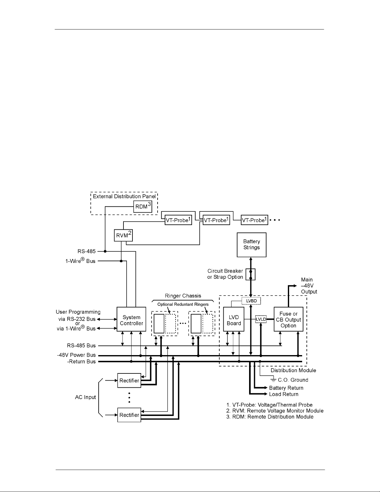
Block Diagrams
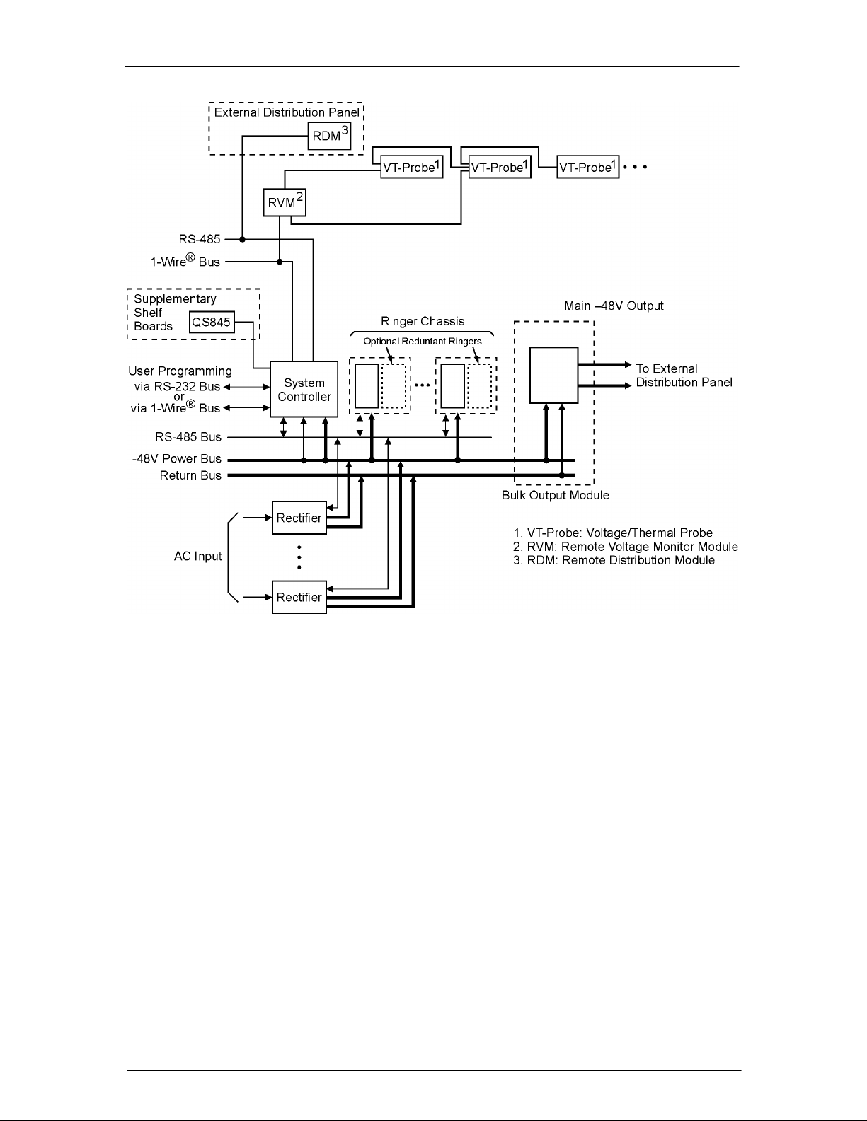
2-1a and 2-1b are basic block diagrams of the CPS6000 System in a single shelf with a
Distribution Module. Figure 2-2 shows the Bulk Output Module in place of the Distribution
Module.
Figure 2-1a: CPS6000 System with Distribution Module
Issue 21 January 2008 10
Page 11
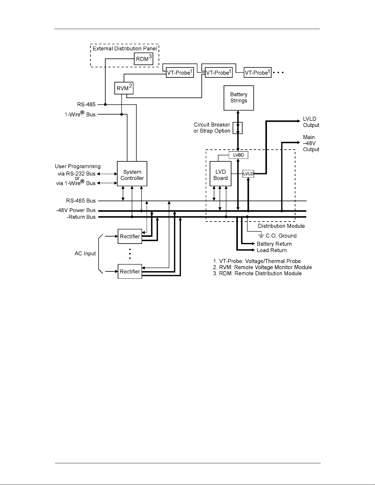
CPS6000 –48V Indoor/Outdoor Power Shelf
Figure 2-1b: CPS6000 System with Distribution Module
Issue 21 January 2008 11
Page 12
CPS6000 –48V Indoor/Outdoor Power Shelf
Figure 2-2: CPS6000 System with Bulk Output Module
Shelf Design
Features
• The shelf is available in 19-inch (phase 2) and 23-inch standard widths and has the
following features:
• Accepts plug-in rectifier, ringer and Distribution Modules.
• 19-inch shelves provide 4 Power Slots.
• 23-inch shelves provide 5 Power Slots
• Rectifiers, Ringer Chassis, and Distribution Modules may be installed in Power Slots.
Permits growth of plant capacity and easy maintenance without service interruption.
Issue 21 January 2008 12
Page 13
CPS6000 –48V Indoor/Outdoor Power Shelf
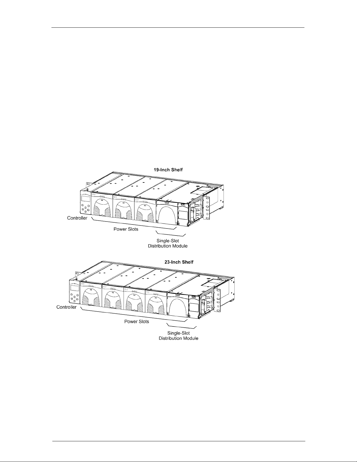
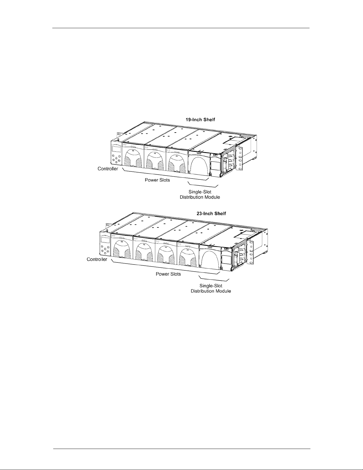
Configurations
The 19-Inch Shelf provides four Power Slots.
The 23-Inch Shelf provides five Power Slots.
Power Slots support Rectifiers, Ringer Chassis, and Distribution Modules. Figure 2-3 shows
the show the locations of the CPS6000 components in the19-inch and 23-inch shelves with
the Single-Slot Distribution Module.
Figure 2-3: CPS6000 Systems with Single-Slot Distribution Module
Issue 21 January 2008 13
Page 14
CPS6000 –48V Indoor/Outdoor Power Shelf
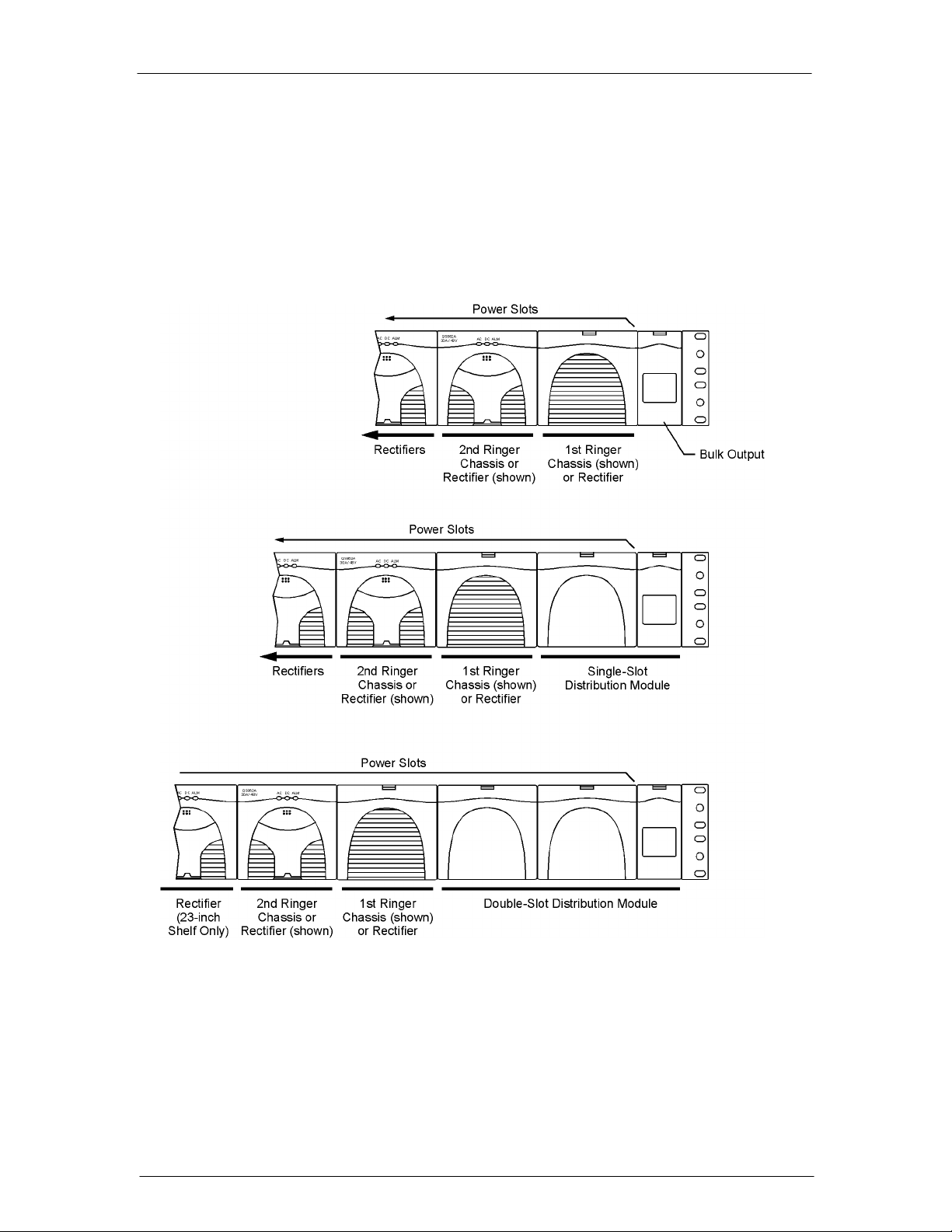
Distribution and Power Module Configurations
The 19-inch shelf has four Power Slots, and the 23-inch shelf has five Power Slots for power
modules (Rectifiers and up to two Ringer Chassis) and distribution options (See 2- 4). With
Bulk Output Distribution only, all slots are available for power modules. The Single-Slot
Distribution Module occupies the right-most Power Slot, and the Double-Slot Distribution
Module occupies the right-most two Power Slots, leaving the remaining Power Slots available
for power modules. Up to two Ringer Chassis can be installed in the right-most remaining
Power Slots.
Figure 2-4: Distribution and Power Module Configurations
Issue 21 January 2008 14
Page 15

CPS6000 –48V Indoor/Outdoor Power Shelf
Battery Reserve System
Introduction
A battery reserve system is a key component for a reliable power system. The CPS6000
provides a primary voltage of -48Vdc that drives load equipment. At the same time, it
provides float and recharge capability for the battery reserve system. If an ac power failure
occurs, the batteries provide power to the load equipment until the ac can be restored.
Types of Batteries
CPS6000 may be used with valve-regulated lead-acid (VRLA) batteries. Up to four strings of
VR-type batteries or equivalent general trade batteries may be connected directly to a
CPS6000 shelf.
Certain Nickel-Cadmium (Ni-Cd) and Lithium-Ion batteries may also be used with the
CPS6000. Please contact your sales representative for details. CPS6000 is also compatible to
Flooded lead-acid batteries.
See Appendix D for detailed descriptions of battery related functions; float and boost
charging, thermal compensation, and system battery test functions.
Issue 21 January 2008 15
Page 16
CPS6000 –48V Indoor/Outdoor Power Shelf
Specifications
Table 2-A: CPS6000 System Specifications
Shelf Single 19-inch or 23-inch shelf
Power Slots per Shelf 4 (19-inch shelf), 5 (23-inch shelf)
Power Units
Installed Position
Installed from the Right
Bulk Output Module
Distribution Module
Ringer Chassis
Installed from the Left
Rectifier Input Distribution Dual ac input (19 and 23-inch shelves)
System Architecture Primary output: 1 primary output power bus per shelf
Primary Power Bus Current
with Bulk Output Module
Output Distribution Primary Bus
Bulk Output Module
Single-Slot and Double-Slot
Distribution Modules
Maximum Discharge Current Based on rectifier capacity. See Note 2
Maximum Recharge Current Installed shelf –48V rectifier capacity minus plant –48V load
Operating Ambient Temperature -40 to 75 °C (-40 to 167 °F), see Note 3
Altitude -200 to 13,000 feet (-61 to 3962 meters). See Note 4
Humidity 10% to 95% non-condensing
Audible Noise < 60 dBA
Radiated and Conducted Emissions FCC Part 15, Class B
Harmonics EN61000-3-2 (IEC61000-3-2)
Voltage Fluctuations EN61000-3-3 (IEC61000-3-3)
Electromagnetic Immunity Meets Telcordia GR-1089-CORE
Electrostatic Discharge EN61000-4-2 Level 3
RF Immunity IEC61000-4-3 Level 3, 10 V/m
EFT IEC61000-4-4 Level 3, No Error; Level 4, No Damage
Surge IEC 61000-4-5 Level 3, No Error; Level 4, No Damage
Conducted Immunity IEC 61000-4-6 Level 3, 10V
Voltage Dips, Interruptions, and Variations IEC 61000-4-11
Earthquake Rating Zone 4, upper floors
Safety Agency Approval
5
Rectifiers
Bulk Output Module
Single-Slot Distribution Module
Double-Slot Distribution Module
Ringer Chassis
Rectifiers (19-inch shelf)
(23-inch shelf)
Individual ac input (19 and 23-inch shelves)
Single ac input (19 and 23-inch shelves)
19-inch shelf: 227A
23-inch shelf: 283A
Battery connections: double-hole lugs to terminate battery
strings.
-48 Vdc bulk power outputs to loads or distribution
• Bullet-style circuit breakers
• GMT-style fuses
See Note 2.
EN55022 (CISPR22), Class B
Underwriters Laboratories (UL) Listed per Subject Letter 1801:
Power Distribution Center for Communications Equipment, and
cUL Certified (CSA 22.2 950): Safety of Information
Technology Equipment
VDE licensed to VDE0805/EN60950
Unit
Max. per
Shelf
1
1
1
2
4
5
Power Slots
Each
0
1
2
1
1
1
Issue 21 January 2008 16
Page 17

CPS6000 –48V Indoor/Outdoor Power Shelf
Rectifiers are individually UL Recognized (UL1950), cUL
Certified (CSA 22.2 234) or evaluated to EN60950 by an EC
Notified Body, as appropriate.
European Economic Community (EEC)
Directives
Note 1: CPS6000 can be used with four strings of batteries depending on Distribution Module
Note 2: When used with Single-Slot and Double-Slot Distribution Modules, maximum output is limited to
200A or the size of the LVD contactor installed (if smaller). See Section 3 for limitations on
maximum currents through Distribution Modules.
Note 3: Operating temperatures and required airflow are different when used with specific rectifiers. See
Tables 2-D through 2-F for rectifier information.
Note 4: For altitudes above 5000 feet, derate the temperature by 3.6 °F per 1000 feet. For altitudes above
1524 meters, derate the temperature by 0.656 degrees Celsius per 100 meters.
Note 5: Power Unit Install Positions:
• Install these units in order beginning with the right most Power Slot
First: Distribution Module
Second: Ringer Chassis
• Install these units in order beginning with the left most Power Slot
First: Rectifiers
EMC Directive 89/336/EEC
Low Voltage Directive 73/23/EEC as amended by Marking
Directive 93/68/EEC
Installation Category
CPS6000 is suitable for connection to ac utility systems where the expected level of lightning
surges complies with ANSI C62.41 Category B or IEC 60664-1 Overvoltage Category II.
A service entrance surge protector is required in applications where the installation categories
can not be classified as being compliant to either ANSI C62.41 Category B or IEC 60664-1
Overvoltage Category II.
CPS6000 rectifiers have been tested for repeated lightning surges typically found in an
Overvoltage Category III installation; however, a service entrance surge protector is
recommended in cabinet applications to bring the power feeds in compliance to the
installation categories above. The service entrance protection should be coordinated with the
protection provided in the power modules.
The power module provides common-mode protection via a 320V MOV in series with a
2500V gas-discharge device and differential-mode protection via a 320V MOV in series with
a 3.5A fuse.
Issue 21 January 2008 17
Page 18
CPS6000 –48V Indoor/Outdoor Power Shelf
Table 2-B: CPS6000 Physical Specifications
Rectifier 3.41 (86.6) 3.4 (86.3) 11.2 (284.5) 5.75 (2.6)
Ringer Chassis 3.41 (86.6) 3.4 (86.3) 11.2 (284.5) 3.45 (1.6)
Ringer 2.4 (61.0) 1.51 (38.4) 9.9 (252) 1.25 (0.6)
19-Inch Shelf 3.41 (86.6) 17.37 (441.2) 12 (304) –
23-Inch Shelf 3.41 (86.6) 20.95 (532.1) 12 (304) –
Single-Slot Distribution Module 3.41 (86.6) 5.1 (129.5) 12 (304) 9 (4.1)
Double-Slot Distribution Module 3.41 (86.6) 8.5 (216) 12 (304) TBM
Bulk Output Module 3.41 (86.6) 1.59 (40.4) 12 (304) 4 (1.8)
23-Inch Frame Mounting
Requirements
19-Inch Frame Mounting
Requirements
Height
in. (mm)
Standard 23 and 26-inch relay racks:
•Vertical mounting centers: 1.0 in. (25 mm) and 1.75 in.
(44 mm)
•Horizontal mounting centers: 22.32 in. (567 mm)
Standard 19-inch relay racks:
•Vertical mounting centers: 1.0 in. (25 mm) and 1.75 in.
(44 mm)
•Horizontal mounting centers: 18.31 in. (465 mm)
Width
in. (mm)
Depth
in. (mm)
front access
13.25 (337)rear access
12.7 (5.77)
front access
13.25 (337)rear access
Weight
lb (kg)
7.5 (3.41)
Table 2-C: CPS6000 Shelf Specifications
Control Unit QS840A / QS841A
Nominal Output Voltages 48/52/54.5 Vdc
Operating Voltage Range 42 to 58 Vdc
Maximum Output Current 200A per 19-inch shelf; 250A per 23-inch shelf
(see Note 1)
Nominal Input Voltage 100/120/200/208/240 Vac
Input Voltage Ranges 85 to 275 Vac
Max Nominal Input Current per Rectifier (based
on 25A rectifier for low line ac, and 50A
rectifier for high line ac)
Boost Voltage 48 to 58 Vdc
Output Voltage Regulation ±0.5%
Output Noise:
Ripple
Wideband Noise
Load Share Accuracy 1.5A (maximum) for QS862A
Maximum Discharge Current
(see Note)
Maximum Recharge Current Installed rectifier capacity minus plant load
Low-Voltage Disconnect 39 to 50 Vdc
Low-Voltage Reconnect 39 to 55 Vdc
Heat Dissipation 177W (604 BTU) per QS862A at full load and
13A at 120 Vac
14.5A at 208 Vac
100 mVrms maximum, 10 Hz to 20 MHz
< 250 mV pk-pk over the range dc to 100 MHz
227A per 19-inch shelf; 284A per 23-inch shelf
120 Vac operation;
Issue 21 January 2008 18
Page 19
CPS6000 –48V Indoor/Outdoor Power Shelf
132W (450 BTU) per QS861A rectifier at full
load and 120 Vac operation;
212W (724 BTU) per QS862A at full load and
240 Vac operation;
130W (445 BTU) per QS861A rectifier at full
load and 240 Vac operation;
267W (911 BTU) per QS865A rectifier at full
load and 240 Vac operation;
Power Factor > 0.98 for loads > 50% of full load
Note: Maximum current is based on Bulk Output Module and 50A QS865A rectifier. System capacity
will decrease with lower rated rectifiers.
Power Slots Available for Rectifiers or Ringer Chassis
Shelf
19-Inch Shelf 4 3 2
23-Inch Shelf 5 4 3
None (Bulk Output Module)
Distribution Module
Single-Wide Double-Wide
Rectifiers
Table 2-D: QS861A Rectifier Specifications
Nominal Output Voltage 48/52/54.5 Vdc
Operating Output Voltage Ranges 42 to 58 Vdc
Boost Voltage 48 to 58 Vdc
Output Current 0 to 15A at 54.5V
Nominal Input Voltage 100/120/200/208/240 Vac (Shutdown from 135 to
150V)
Input Voltage Ranges 85 to 275 Vac
Input Current 8A at 120 Vac
4.4A at 208 Vac
Operating Frequency Range 45 to 66 Hz
Operating Temperature -40 to +75 °C
Output Voltage Regulation ±0.5%
Output Noise, Ripple 250 millivolts peak to peak maximum, over the
range dc to 100 MHz
Load Share Accuracy 1.5A maximum deviation between rectifiers
Heat Dissipation (per rectifier, full load) 132W (450 BTU) at 120 Vac operation
130W (445 BTU) at 240 Vac operation
Power Factor >0.99 (low-line), >0.98 (high line)
Selective High-Voltage Shutdown Above 58 Vdc
Backup High-Voltage Shutdown Above 60 Vdc for 1 millisecond
Table 2-E: QS852A Rectifier Specifications
Nominal Output Voltage 48/52/54.5 Vdc
Operating Output Voltage Ranges 42 to 58 Vdc
Boost Voltage 48 to 58 Vdc
Issue 21 January 2008 19
Page 20

CPS6000 –48V Indoor/Outdoor Power Shelf
Output Current 0 to 20A at 54.5V
Nominal Input Voltage 1200/208/240 Vac
Input Voltage Ranges 150 to 275 Vac
Input Current 6A at 208 Vac
Operating Frequency Range 45 to 66 Hz
Operating Temperature -40 to +75 °C
Output Voltage Regulation ±0.5%
Output Noise, Ripple 250 millivolts peak to peak maximum, over the
range dc to 100 MHz
Load Share Accuracy 1.5A maximum deviation between rectifiers
Heat Dissipation (per rectifier, full load) 133 W (454 BTU) at 240 Vac operation
Power Factor >0.98 (high line)
Selective High-Voltage Shutdown Above 58 Vdc
Backup High-Voltage Shutdown Above 60 Vdc for 1 millisecond
Table 2-F: QS853A Rectifier Specifications
Nominal Output Voltage 48/52/54.5 Vdc
Operating Output Voltage Ranges 42 to 58 Vdc
Boost Voltage 48 to 58 Vdc
Output Current 0 to 25A at 54.5V (100/120 Vac)
Nominal Input Voltage 200/208/240 Vac
Input Voltage Ranges 150 to 275 Vac (Shutdown from 135 to 150V)
Input Current 7.4A at 208 Vac
Operating Frequency Range 45 to 66 Hz
Operating Temperature -40 to +75 °C
Output Voltage Regulation ±0.5%
Output Noise, Ripple 250 millivolts peak to peak maximum, over the
range dc to 100 MHz
Load Share Accuracy 1.5A maximum deviation between rectifiers
Heat Dissipation (per rectifier, full load) 212W (724 BTU) at 200 to 240 Vac operation
Power Factor >0.98 for loads > 50% full load
Selective High-Voltage Shutdown Above 58 Vdc
Backup High-Voltage Shutdown Above 60 Vdc for 1 millisecond
Table 2-G: QS862A Rectifier Specifications
Nominal Output Voltage 48/52/54.5 Vdc
Operating Output Voltage Ranges 42 to 58 Vdc
Boost Voltage 48 to 58 Vdc
Output Current 0 to 25A at 54.5V (100/120 Vac)
0 to 30A at 54.5V (200/240 Vac)
Nominal Input Voltage 100/120/200/208/240 Vac
Input Voltage Ranges 85 to 275 Vac (Shutdown from 135 to 150V)
Input Current 13A at 120 Vac
8.8A at 208 Vac
Operating Frequency Range 45 to 66 Hz
Operating Temperature -40 to +75 °C
Output Voltage Regulation ±0.5%
Issue 21 January 2008 20
Page 21

CPS6000 –48V Indoor/Outdoor Power Shelf
Output Noise, Ripple 250 millivolts peak to peak maximum, over the
range dc to 100 MHz
Load Share Accuracy 1.5A maximum deviation between rectifiers
Heat Dissipation (per rectifier, full load) 177W (604 BTU) at 100 to 120 Vac operation
212W (724 BTU) at 200 to 240 Vac operation
Power Factor >0.98 for loads > 50% full load
Selective High-Voltage Shutdown Above 58 Vdc
Backup High-Voltage Shutdown Above 60 Vdc for 1 millisecond
Table 2-H: QS864A Rectifier Specifications (Preliminary)
Nominal Output Voltage 48/52/54.5 Vdc
Operating Output Voltage Ranges 42 to 58 Vdc
Boost Voltage 48 to 58 Vdc
Output Current 0 to 40A at 54.5V
Nominal Input Voltage 200/208/240 Vac
Input Voltage Ranges 150 to 275 Vac
Input Current 11.8A at 208 Vac
Operating Frequency Range 45 to 66 Hz
Operating Temperature -40 to +75 °C
Output Voltage Regulation ±0.5%
Output Noise, Ripple 250 millivolts peak to peak maximum, over the
range dc to 100 MHz
Load Share Accuracy 1.5A maximum deviation between rectifiers
Heat Dissipation (per rectifier, full load) 240W (819 BTU) at 240 Vac operation
Power Factor >0.98 for loads > 50% full load
Selective High-Voltage Shutdown Above 58 Vdc
Backup High-Voltage Shutdown Above 60 Vdc for 1 millisecond
Table 2-I: QS865A Rectifier Specifications
Nominal Output Voltage 48/52/54.5 Vdc
Operating Output Voltage Ranges 42 to 58 Vdc
Boost Voltage 48 to 58 Vdc
Output Current 0 to 50A at 54.5V
Nominal Input Voltage 200/208/240 Vac
Input Voltage Ranges 150 to 275 Vac
Input Current 14.5A at 208 Vac
Operating Frequency Range 45 to 66 Hz
Operating Temperature -40 to +65 °C
Output Voltage Regulation ±0.5%
Output Noise, Ripple 250 millivolts peak to peak maximum, over the
range dc to 100 MHz
Load Share Accuracy 1.5A maximum deviation between rectifiers
Heat Dissipation (per rectifier, full load) 267W (911 BTU) at 240 Vac operation
Power Factor >0.98 for loads > 50% full load
Selective High-Voltage Shutdown Above 58 Vdc
Backup High-Voltage Shutdown Above 60 Vdc for 1 millisecond
Issue 21 January 2008 21
Page 22
CPS6000 –48V Indoor/Outdoor Power Shelf
Table 2-J: QS820A Ringer Specifications
Input Voltage -40 to -57 Vdc See Output VA Thermal Limiting.
Nominal Input Voltage -48 Vdc
Input Current 5 A max.
Output
Voltage
ac tolerance ± 5 Vac
Regulation ±5% ac component only
dc Offset
dc Offset Tracking
Harmonic Distortion 5% THD
Crest Factor 1.21 to 1.51
Output Frequency 15 to 50 Hz
Frequency tolerance ± 1 Hz
Output VA 100 VA
Thermal Limiting Output VA may be reduced by reducing Vac when
Load Power Factor Operating: 0.5 Leading to 0.9 Lagging
Operating Temperature -40 to +75 °C See Output VA Thermal Limiting.
Heat Dissipation 50 W (170 BTU / hr)
Under Voltage Shutdown 50% of Output Vac Set Point
ac Component
Type of ringing
Battery Backed
Ground Backed
Ground Backed no-dc
Error
65 to 100 Vac
Factory Default: 100Vac
• -40 to +57 Vdc Battery Backed
• +40 to +57 Vdc Ground Backed
• 0 Vdc Offset Disabled
• dc Offset tracks dc Input Voltage
• Factory Default: Enabled
• Battery or Ground Backed is selected by Ringer
Chassis jumper J12 or by external connection of
Ring Rtn to Battery or to Ground. Factory Default:
Battery Backed by Jumper
See figures in the Ringer section.
± 3 Vdc
Factory Default: 20 Hz
operating simultaneously above 50°C and less than
-50Vdc input.
Vac is reduced only sufficiently to prevent damage to
the ringer.
No Damage: 0 Leading to 0.7 Lagging
While shutdown due to external fault, restart will be
performed at approximately 2 minute intervals.
Table 2-K: QS840A and QS841A Control Unit Specifications
Operating Input Voltage Range 38 to 60 Vdc
Input Power 6.0 watts maximum
Plant Parameter Setting Through front panel LCD display and menu keys or with
IBM compatible PC with RS-232 port. 841 also has 10/100
Baset-T network ability
Alarm Contact Ratings 60 Vdc, 0.5A, Form-C
Operating Temperature -40 to +75 °C
Issue 21 January 2008 22
Page 23

CPS6000 –48V Indoor/Outdoor Power Shelf
Table 2-L: QS845A Supplementary Board Specifications
Operating Input Voltage Range Input power through QS840A or QS841A
Plant Parameter Setting None, communicates with shelf components QS840A/QS841A
Alarm Contact Ratings None
Operating Temperature -40 to +75 °C
Issue 21 January 2008 23
Page 24

CPS6000 –48V Indoor/Outdoor Power Shelf
3 Engineering and Ordering
Engineering Information
Introduction
This section discusses the factors to be considered in determining the number of rectifiers and
ringers required in both non-redundant and redundant battery plants.
Rectifier Sizing (Non-Redundant Systems)
In non-redundant systems, the installed rectifier capacity of the battery plant must be
sufficient to provide the current required for the load during normal operations as well as the
current required to recharge the battery following ac power outages.
For the telecommunications industry, the system load current is known as the average busyhour current. (The average busy-hour current drain is defined as the average busy-hour
current drain during busy season with the plant operating at the normal voltage.) Therefore,
the minimum installed rectifier capacity (mirc) is the sum of the average busy-hour (abh)
current and the required battery recharge current, or
mirc = abh + recharge current
The battery recharge current is determined by two system considerations: the maximum time
the system is required to operate in the absence of ac power (reserve time), and the time
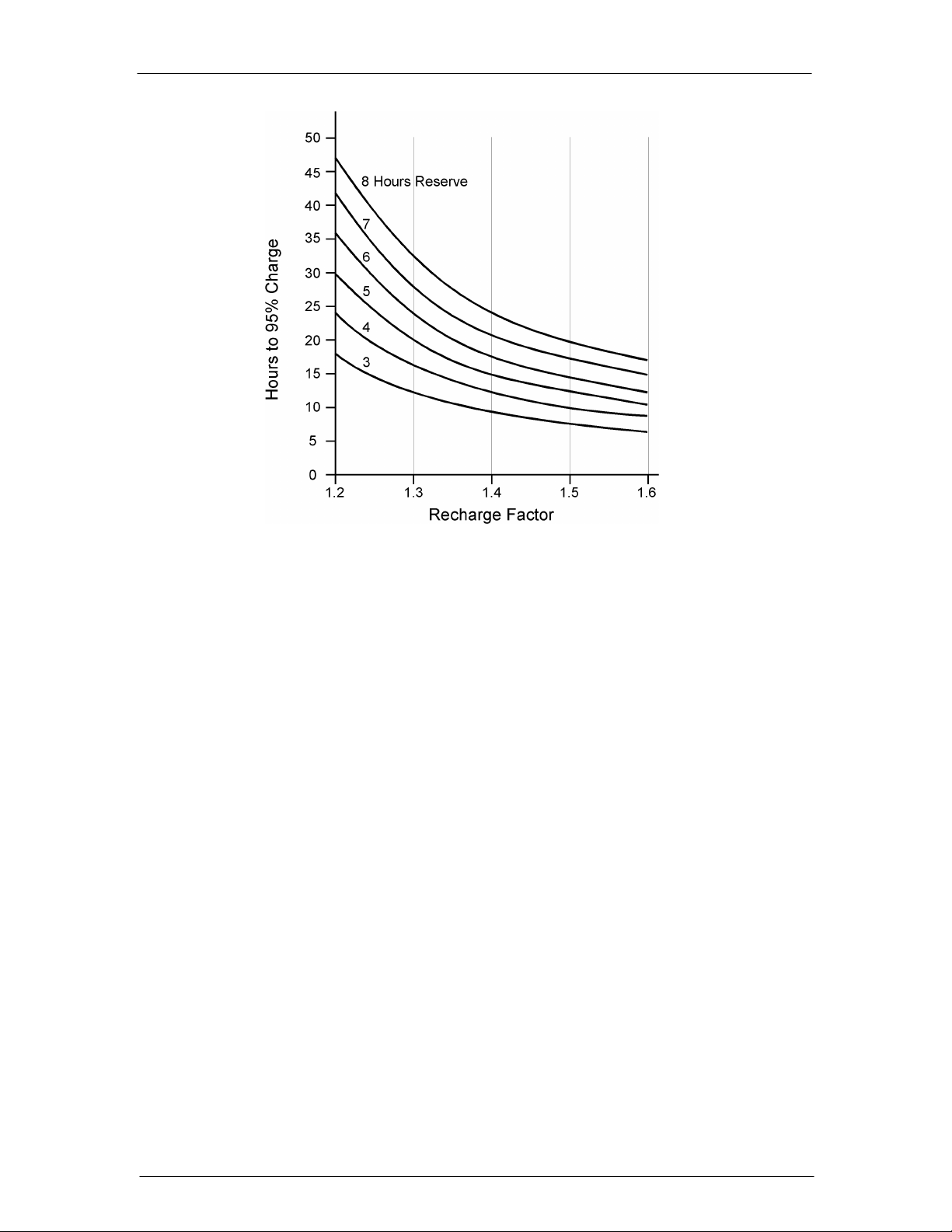
allocated to recharge the battery after ac power returns. These two times and Figure 3-1 may
be used to determine the recharge factor. This factor, when multiplied by the average busyhour current, determines the minimum installed rectifier capacity, or:
mirc = abh x recharge factor
The mirc divided by the individual rectifier capacity determines the number of rectifiers (of
equal capacity) required for a non-redundant system.
Rectifier Sizing (Redundant Systems)
In redundant systems, a spare on-line rectifier is included so that the loss of any one rectifier
will not cause the available plant capacity to fall below the required minimum installed
rectifier capacity. Thus, the loss of a rectifier will not affect the normal system operation nor
will it cause the batteries to discharge, and will allow the batteries to recharge in the required
time.
In cases where the additional spare rectifier will provide the required battery recharge current,
the mirc satisfies the requirements for both non-redundant and redundant systems. In other
cases, rectifiers in addition to the redundant rectifier may be required to provide the battery
recharge current. Typically, the number of spare rectifiers required for a redundant system is
the larger of one spare rectifier or 200% of the rated load.
Issue 21 January 2008 24
Page 25
CPS6000 –48V Indoor/Outdoor Power Shelf
Figure 3-1: Recharge Factor vs. Recharge Time
Plant Configuration Examples
1. To illustrate the relationships between mirc, abh current drains, the recharge factor, and
battery recharge current for non-redundant and redundant systems, consider the following
examples. Note that the QS862A rectifier provides 25A at 54.5 Vdc (100-120 Vac) and
30A at 54.5 Vdc (200-240Vac).
A battery plant is required to provide a load current of 50 amperes, have an 8-hour
discharge time (reserve time) and recharge to 95% of battery capacity in 24 hours.
Determine the number of rectifiers required for non-redundant systems.
From Figure 3-1, the recharge factor is 1.38.
mirc = abh x recharge factor
mirc = 50 x 1.38 = 69 amperes
For low line ac using QS862A 25A (100-120 Vac) rectifiers, three rectifiers (69/25 =
2.76) are required to provide the minimum installed capacity of 69 amperes for a nonredundant system. If one rectifier fails, the remaining rectifiers will provide the abh
capacity.
2. An alternate method to calculate the number of rectifiers necessary is to utilize power. In
the above example, the requisite current is 50A. As most battery plant loads are looking
into constant-power loads, the 50A would increase as the battery voltage decreases during
battery discharge. Assuming the 50A is the current being drawn from the load at the plant
float voltage of 54.5V, the total power being drawn by the load is 2725W (54.5V x 50A).
We can utilize the recharge factors from Figure 3-1 and use a modified mirc formula,
Issue 21 January 2008 25
Page 26

CPS6000 –48V Indoor/Outdoor Power Shelf
therefore:
mirc = power x recharge factor
mirc = 2725W x 1.38 = 3761W
In this high line ac example using QS862A 1635W (200-240 Vac) constant power
rectifiers, three rectifiers (3761/1635 = 2.3) are needed to support the load and recharge
the batteries within the requisite time.
Ringer and Ringer Chassis
Ringer Chassis each support one 100 VA ringing output. Redundant ringing outputs require
two Ringers in each Ringer Chassis.
Ordering Information
Ordering Guide
An ordering guide may be downloaded from the Lineage Power web site. This guide will
augment the information found here.
Note: Ordering information here is presented only from the viewpoint of miscellaneous
item ordering and may not be complete. Complete System ordering should done using
the ordering guide only.
Comcodes
The CPS6000 can be ordered by 9-digit numeric character sets called comcodes. The
following guides you through the comcode selection process in creating a power system.
Please refer to the product description section on the individual components for more details.
Power Shelves
Shelves are available in 23-inch (584 mm) and 19-inch (483 mm) rail widths. Mounting
hardware is provided. Refer to Ordering Guide for other shelf types.
Baffle
A 1U tall baffle is available to mount between shelves, below the shelf or above the shelf. See
Appendix F for application information.
Distribution Modules
The Platform has standard single slot, dual slot, front bulk and rear bulk output module
options. An external 23” distribution panel is also available for systems with the bulk output.
Battery breakers are available in lieu of the battery straps. However, maximum current
allowed through each battery breaker is 50A instead of the 100A through the battery strap.
For load breakers in a single slot distribution module, a max of two 60A load breakers can be
used. If only a single breaker is used in the topmost position, a 70A breaker may be used
Issue 21 January 2008 26
Page 27
CPS6000 –48V Indoor/Outdoor Power Shelf
Office Alarm Cable
WARNING
Disconnect alarm cable before cutting it to length. Cutting the alarm cable while it is
plugged into the controller will damage the controller.
A cable assembly is available that mates to the host-interface connector on the controller
allowing access to alarms. This cable is terminated on one end with a connector that mates to
the Distribution Module host-interface connector, and un-terminated on the other end. Refer
to the ordering guide for cable lengths available
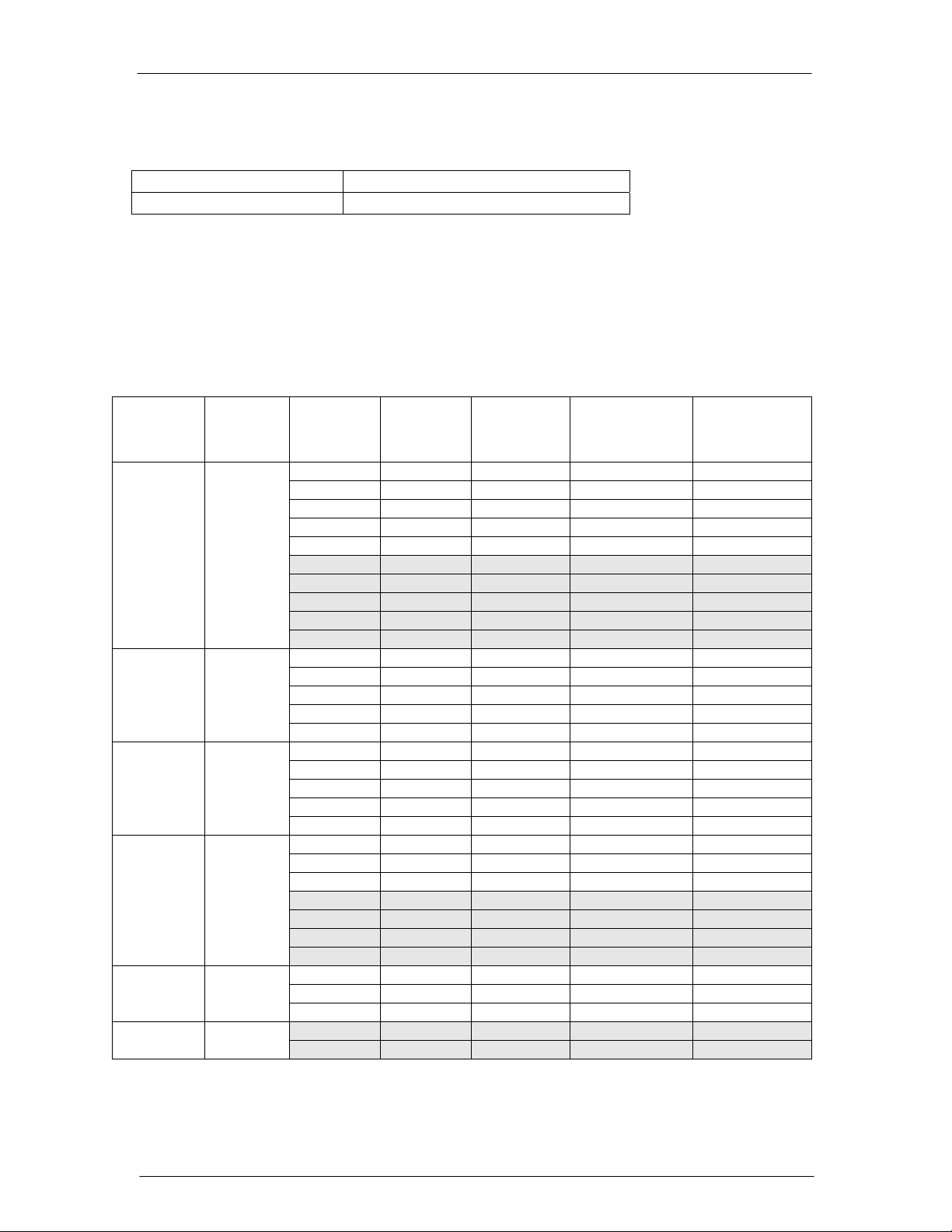
Distribution Module Circuit Breakers
The following bullet-style circuit breakers, which have been accepted for use in dc load and
battery applications, are available for the current Distribution Module. These breakers only
alarm for a trip condition. For a single slot distribution module, a max of two 60A load
breakers can be used. If only a single breaker is used in the topmost position, a 70A breaker
may be used
Size (Amps) Comcode Size (Amps) Comcode
3 407998137 25 407998194
5 407998145 30 407998202
10 407998152 45 407998210
15 407998160 50 407998228
16 407998178 60 407998236
20 407998186 70 407998244
Some versions of the distribution module accept breakers that alarm for trip or open
condition. The comcodes for such breakers are provided below. These breakers can ONLY be
used with specific distribution modules
Size (Amps) Comcode Size (Amps) Comcode
3 CC408606834 30 CC408606891
5 CC408606842 40 CC408606900
10 CC408606850 45 CC408606917
15 CC408606867 50 CC408606925
20 CC408606875 60 CC408606933
25 CC408606883
Caution - Please check the type of breaker the distribution module
accepts before using the above comcodes
Pluggable Strap
Size(Amps) Comcode
100A Pluggable Strap CC109106548
Issue 21 January 2008 27
Page 28
CPS6000 –48V Indoor/Outdoor Power Shelf
Distribution Module GMT Fuses
The following GMT fuses have been accepted for use in dc load applications, are available
for the current Distribution Module.
Size (Amps) Comcode Size (Amps) Comcode
0.25 405006222 7.5 405725433
0.5 406976894 10 406159236
1.33 405673146 12 407845197
2 405181983 15 406473959
3 406976985 20 408555453
5 406159061
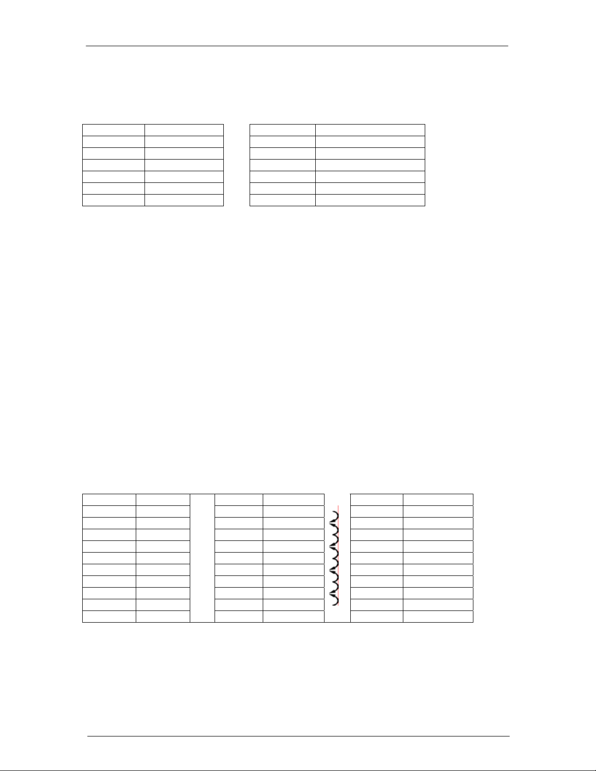
The following shows the possible fuse loading scenario for the Single-Slot and Double-Slot
Distribution Modules. 20A fuse positions can be used only with factory wiring. When using
20A fuses, adjacent fuse positions must be left open.
For the Single-Slot Distribution Module with 10 GMT fuses, Field installation is only rated
for 10A fuses. No more than 80A may be carried through the 10 fuse positions, or 40A
through each half section. 15A and lower rated fuses may be used in any combination and
position, as long as they do not violate the previous 80A/40A rule.
For the Single-Slot Distribution Module with 5 GMT fuses, a maximum load of 32 A is
permitted with restrictions on the fuse positions. Specifically:
Position F1 defined as the bottom fuse position and F5 as the top fuse position.
1. Configuration #1 - F1+F2 <= 15A, F3<=15A, and F5+F4<= 10A
2. Configuration #2 - F1<=15A; F2=No Fuse; F3<=15A; F4=No Fuse; F5<=10A 3.
For the Double-Slot Distribution Module, each 8-fuse board can support a maximum of 80A.
Single-Slot Distribution Module
Position Max Fuse Position Max Fuse Position Max Fuse
10 10 15A 8 15A/20A
9 20A 9 7
8 8 15A 6 15A/20A
7 20A 7 5
6 6 15A 4 15A/20A
5 5 3
4 20A 4 15A 2 15A/20A
3 3 1
2 20A 2 15A
1 1 15A
(Arrows indicate
alternate positions)
Double-Slot
Distribution Module
Issue 21 January 2008 28
Page 29
CPS6000 –48V Indoor/Outdoor Power Shelf
Controller
There are two controller options for the CPS6000. The QS840A system controller allows for
control and monitoring of system functions and setting of all system parameters. The QS841
provides integrated Ethernet access and other enhanced features. Refer to Section 5 for more
controller details and Appendix A for programming information. The QS845A supplemental
kit allows up to 3 supplemental shelves to be controlled by the QS840A/QS841A controller
on the primary shelf.
Rectifiers
The constant-power rectifiers each occupy a single slot in the CPS6000 shelf. If a full
complement of rectifiers is not required, a rectifier slot filler may be to cover empty rectifier
slots. The slot filler is not necessary from an earthquake standpoint.
Model Amperage Comcode
QS861A Rectifier 15A low and high line ac 108993531
QS852A Rectifier 20A high line ac CC109106440
QS853A Rectifier 25A high line ac CC109121290
QS862A Rectifier 25A low line/30A high line ac 108986704
QS864A Rectifier 40A high line ac 108994513
QS865A Rectifier 50A high line ac 108990074
QS850 Slot Filler N/A 108994273
Ringer Chassis
Ringer Chassis each occupy a single Power Slot in the CPS6000 Shelf.
Ringer Chassis Comcode
QS820M Ringer Chassis 108991262
Ringer Output Cable
Ringer Cables one per Ringer Output (Ringer Chassis).
Item Comcode
Ringer Output Cable H569-470 G kit – 15’ cable
with connector for CPS6000/CPS2000 shelf on
one end and unterminated leads on the other
end.
Ringer Output Cable – 150 ft CC848804765
Commercial - Molex:
Plug 39-01-4031
Socket (3 per plug):
Terminal Type 5556
16 AWG 39-00-0079
18 AWG 39-00-0059
Tool 11-01-0197
847922101
Commercial
Ringers
Up to two Ringers plug into a Ringer Chassis.
Issue 21 January 2008 29
Page 30
CPS6000 –48V Indoor/Outdoor Power Shelf
One Ringer per Ringer Chassis is non-redundant (simplex).
Two Ringers per Ringer Chassis is 1 + 1 redundant (duplex).
Ringer Comcode
QS820A Ringer 108990082
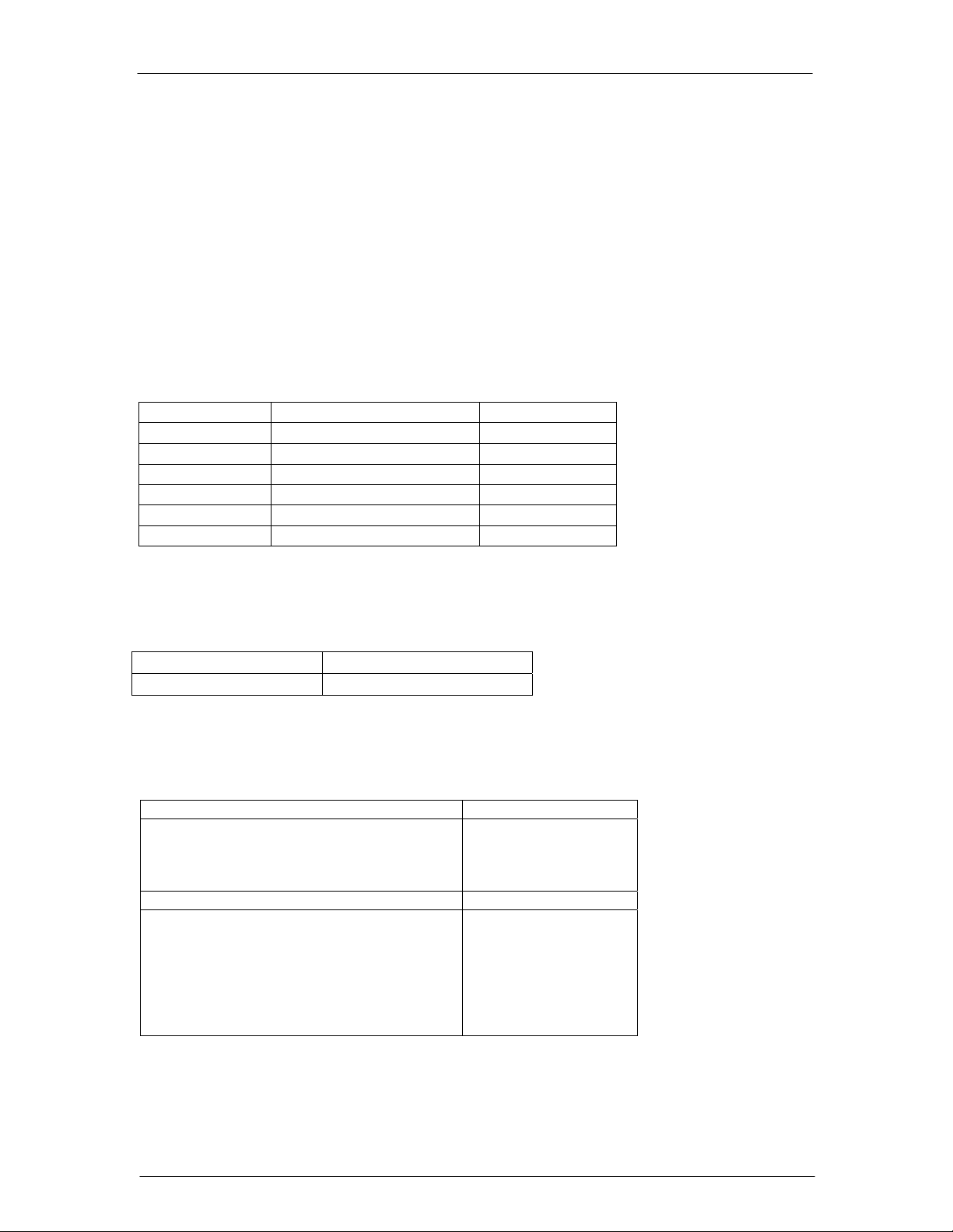
AC Power Cables
An ac power cable must be ordered. A standard ac cable set will not fit in the CPS6000 shelf.
Verify that the sum of the input currents for all the rectifiers served by an ac circuit breaker
does not exceed 80% of the breaker’s rating.
Table 3-A: Rectifier AC Input Current Table
Lineage
Power
Rectifier (A)
Model
Number of
Rectifier
Nominal
Input
Voltage
Number of
Rectifiers
per AC feed
Nominal AC
Current (A)
Minimum Circuit
Breaker value
recommended
(A)*
75°C Minimum
Recommended
Wire Gauge
(AWG)*
120 1 7.8 15 14
120 2 15.6 20 12
120 3 23.4 30 10
120 4 31.2 40 8
15A QS861A
120 5 39.1 50 8
208 1 4.4 15 14
208 2 8.8 15 14
208 3 13.2 20 12
208 4 17.6 25 10
208 5 22.0 30 10
208 1 6 15 14
208 2 12 15 14
20A QS852A
208 3 18 25 10
208 4 24 30 10
208 5 30 40 8
208 1 7.4 15 14
208 2 14.8 20 12
25A QS853A
208 3 22.2 30 10
208 4 29.6 40 8
208 5 37.0 50 8
120 1 13.0 20 12
120 2 26.0 35 8
120 3 39.1 50 8
25/30A QS862A
208 1 8.8 15 14
208 2 17.6 25 10
208 3 26.4 35 8
208 4 35.3 45 8
208 1 11.8 15 14
40A QS864A
208 2 23.5 30 10
208 3 35.3 45 8
50A QS865A
208 1 14.5 20 12
208 2 29.1 40 8
*Conduit and further temperature deratings may be required in some installations .Cross-check table with
local code and regulation requirements
Issue 21 January 2008 30
Page 31

CPS6000 –48V Indoor/Outdoor Power Shelf
Thermal Compensation
Thermal Compensation: For thermal compensation, the QS873A Voltage/Thermal probe
(VT-Probe) and its associated cables must be ordered. Refer to Section 5 for details on their
interconnection, and Section 9 for more information on VT-Probes. The probe is provided
with a weatherproof case.
Thermal Compensation/Voltage Monitoring: When voltage monitoring for battery string
voltage imbalance detection is to be implemented in addition to thermal compensation, the
VT-probe and its associated cables must be ordered. Refer to Section 5 for details on their
interconnection, and Section 9 for more information on VT-Probes and voltage monitoring.
Remote Distribution Monitor Module
The Remote Distribution Monitor Module allows the CPS6000 system controller to monitor
for open circuit breakers and fuses, monitor current through a battery shunt, and
monitor/control low-voltage disconnect contactors at an external distribution panel that is
bulk-fed from the CPS6000 system. See Section 11 for more details.
Inter-Shelf Kit for Multiple Shelves
Supplementary bulk-output shelves may be added to a bulk-output primary shelf to create a
larger plant. Only the primary shelf requires a controller. The inter-shelf kit contains a QS845
shelf controller (with blank faceplate) and a connecting cable with connectors on both ends.
Refer to Appendix F for thermal considerations while paralleling shelves.
Lugs
Please refer to ordering guide H569-470 for lugs specific to distribution modules. The
following table is generic and needs to be used in conjunction with the ordering guide.
Note: TEPS lugs in the WP91412 specification are Burndy parts. The Panduit and T&B (and
any others) may have different dimensions.
WP-91412
GA Description
2 Straight, STR 54 405348202 YA2CL-2TC14 LCD2-14A-Q 54207 (STR)
2 Straight, FLEX 8 405347683 YAV2C-L2TC14-FX LCDX2-14A-E 54208 (Flex)
2 45°, STR ? ? YA2CL-2TC14-45 LCD2-14AH-Q 54207UF (STR)
2 45°, FLEX 193 408210524 YAV2C-L2TC14-FX-45 LCDX2-14AH-E 54208UF (Flex)
4 Straight, STR / FLEX 5 405347576 YAV4C-L2TC14-FX LCDX4-14A-L (FLEX)
4 45°, STR / FLEX ? ? YAV4C-L2TC14-FX-45 LCDX4-14AH-L (FLEX)
6 Straight, STR / FLEX 3 405347519 YAV6C-L2TC14-FX LCDX6-14A-L (FLEX)
6 45°, STR / FLEX ? ? YAV6C-L2TC14-FX-45 LCDX6-14AH-L (FLEX)
8 Straight, STR / FLEX 75 406021626 YA8CL2TC14 LCDX8-14A-L (FLEX)
8 45°, STR / FLEX ? ? YA8CL2TC14-45 LCDX8-14AH-L (FLEX)
List
Comcode Burndy Equivalent Panduit Similar T&B Similar
54206 (STR)
LCD4-14A-L (STR)
LCD4-14AH-L (STR)
LCD6-14A-L (STR)
LCD6-14AH-L (STR)
LCD8-14A-L (STR)
LCD8-14AH-L (STR)
54206 (FLEX)
54206UF (STR)
54206UF (FLEX)
54205 (STR)
54205 (FLEX)
54205UF (STR)
54205UF (FLEX)
542040410 (STR)
542040410 (FLEX)
N/A
Issue 21 January 2008 31
Page 32

CPS6000 –48V Indoor/Outdoor Power Shelf
4 Safety
Safety Statements
Please read and follow all safety instructions and warnings before installing, maintaining, or
repairing the CPS6000 System:
• The CE Mark demonstrates compliance with the European Union Council Directives
for Low Voltage and EMC.
• The CPS6000 platform is Underwriters Laboratories (UL) Listed per Subject Letter
1801, DC Power Distribution Centers for Telecommunications Equipment.
• CPS6000 shelves equipped with QS820A ringers (in development) have hazardous
secondary voltages on the secondary bus output connectors.
• Install only in restricted access areas (dedicated equipment rooms, equipment closets,
or the like) in accordance with articles 110-16, 110-17, and 110-18 of the U.S.
National Electric Code (NEC), ANSI/NFPA No. 70, and pursuant to applicable local
codes.
• This equipment is to be used in controlled environments (an area where the humidity is
maintained at levels that cannot cause condensation on the equipment, the
contaminating dust is controlled, and the steady-state ambient temperature is within
the range specified).
• This equipment has been evaluated for continuous use in ambient temperature from -
40°C to 75°C when used with the QS862A rectifier.
• This equipment must not be installed over combustible surfaces.
• For installations in the United States, Listed compression connectors are to be used to
terminate Listed field-wired conductors where required. For all installations, the
appropriate connector is to be applied only to the correct size conductor as specified
by the connector manufacturer, using only the connector manufacturer's recommended
tooling or tooling approved for that connector.
• If the proper connector for the country of installation is not provided, obtain appropriate
connectors and follow manufacturer’s and all local requirements for proper
connections. All national and local rules and regulations should be followed when
making field connections.
• Load connections to Bulk Output Modules should be made in close proximity to the
power shelf.
• The main output voltage (48V) meets SELV requirements.
Issue 21 January 2008 32
Page 33

CPS6000 –48V Indoor/Outdoor Power Shelf
• Insulation on field-wired conductors should be rated no less than 90° Celsius. Wire
conductor size should be sized per electrical codes for 75° Celsius wire, and based on
the ampacity of the associated protection device. Wiring internal to enclosed
equipment cabinets should be rated at 105° Celsius (minimum).
• Torque electrical connections to the values specified on labels or in the product
documentation.
• Battery input cables must be dressed to avoid damage to the conductors (caused by
routing around sharp edges or routing in areas where wires could get pinched) and
undue stress on the connectors.
• Alarm contacts on the office alarm connector (J1) are not fused within the distribution
panel; therefore, current limiting protection for these contacts must be provided by
external circuits. Maximum ratings for alarm connections are 60Vdc and 0.5 amperes.
Exceeding these maximum ratings could result in fire or damage to the unit.
• Fuse and/or circuit breaker loads must not exceed 80% of the fuse and/or circuit
breaker current rating. Distribute loads across the panel.
• The short circuit current capability of the battery input to the distribution panel must
not exceed 10,000A.
• AC branch circuits to this equipment must be protected with either fuses or circuit
breakers sized as required by the National Electric Code (NEC) and/or local codes.
The maximum size of the over-current protector is based on the type of shelf. Refer to
the equipment ratings to assure rating of equipment will not exceed 80% of the value
of the protector chosen.
• An accessible ac disconnect/protection device to remove ac power from the equipment
in the event of an emergency must be provided.
• High leakage currents are possible due to contribution from simultaneous multiple AC
input connections. Earth ground connection is essential before connecting the ac
source to the shelf. This connection must be achieved by ensuring that the C.O.
grounding stud is connected as shown in the Installation Section, or quality service
personnel shall ensure that the rack system is bonded per the provision below.
• In enclosed equipment cabinets, the CPS6000 mounting framework must be connected
directly to the cabinet ac service ground bus. For applications in huts, vaults, and
central offices, the CPS6000 mounting framework must be connected to the system
integrated ground grid.
• Installing fuses or circuit breakers not specified for use in these distribution modules
may result in injury to service personnel or equipment damage. Use only replacement
parts listed in this manual and on the equipment drawings.
• The telecom-type (e.g., GMT type) fuses can produce sparks during interruption or
clearing of a fault on a high energy circuit. Use only fuses provided with safety caps
for this type of circuit. Installing telecom-type fuses not equipped with safety caps
may result in injury to service personnel.
Issue 21 January 2008 33
Page 34

CPS6000 –48V Indoor/Outdoor Power Shelf
• While installing batteries, follow all safety precautions outlined in the appropriate
battery product manuals.
• The terminal block for the GMT fuse panel is rated for 20A with factory wiring, but
only 10A for field installation.
• All ac inputs for the J85470S1 L12 and L13 must be connected to maximum 60A panel
board breakers from maximum two ac conduit connections.
• CPS6000 outputs are not connected to earth. Earthing of rectifier outputs may be
performed externally to the shelf at a “ground window” or “mesh ground”. Connection
of Ringer tip outputs to CPS6000 Battery or Ground is optional via Ringer Chassis
jumper or external connection.
• The QS841 has an IEEE 802.3 compliant 10Base-T network interface with a
grounded connector shield.. Where intra building lightning surge protection is of
concern, Lineage Power recommends the use of a shielded cable, where both ends are
tied to ground. This cable must be supplied by the user. (example: CAT 5 E STP)
Issue 21 January 2008 34
Page 35

CPS6000 –48V Indoor/Outdoor Power Shelf
Warning Statements and Safety Symbols
The symbols may sometimes be accompanied by some type of statement; e.g., “Hazardous
voltage/energy inside. Risk of injury. This unit must be accessed only by qualified
personnel.” Signal words as described below may also be used to indicate the level of hazard.
Indicates the presence of a hazard that will cause death or severe personal
DANGER
WARNING
CAUTION
injury if the hazard is not avoided.
Indicates the presence of a hazard that can cause death or severe personal
injury if the hazard is not avoided.
Indicates the presence of a hazard that will or can cause minor personal
injury or property damage if the hazard is not avoided.
This symbol identifies the need to refer to the equipment instructions for
important information.
These symbols (or equivalent) are used to identify the presence of hazardous
ac mains voltage.
This symbol is used to identify the presence of hazardous ac or dc voltages.
It may also be used to warn of hazardous energy levels.
One of these two symbols (or equivalent) may be used to identify the
presence of rectifier and battery voltages. The symbol may sometimes be
accompanied by some type of statement, for example: “Battery voltage
present. Risk of injury due to high current. Avoid contacting conductors with
uninsulated metal objects. Follow safety precautions.”
One of these two symbols may be used to identify the presence of a hot
surface. It may also be accompanied by a statement explaining the hazard. A
symbol like this with a lightning bolt through the hand also means that the
part is or could be at hazardous voltage levels.
This symbol is used to identify the protective safety earth ground for the
equipment.
This symbol is used to identify other bonding points within the equipment.
This symbol is used to identify the need for safety glasses and may
sometimes be accompanied by some type of statement, for example: “Fuses
can cause arcing and sparks. Risk of eye injury. Always wear safety glasses.”
Issue 21 January 2008 35
Page 36

CPS6000 –48V Indoor/Outdoor Power Shelf
Precautions
When working on or using this type of equipment, the following precautions should be noted:
• This unit must be installed, serviced, and operated only by skilled and qualified
personnel who have the necessary knowledge and practical experience with electrical
equipment and who understand the hazards that can arise when working on this type of
equipment.
• The equipment could be powered by multiple ac inputs. Ensure that the appropriate
circuit protection device for each ac input being serviced is disconnected before
servicing the equipment. Do not disconnect permanent bonding provisions unless all ac
inputs are disconnected.
• Batteries may be connected in parallel with the output of the rectifiers. Turning off the
rectifiers will not necessarily remove power from the bus. Make sure the battery power
is also disconnected and/or follow safety procedures while working on any equipment
that contains hazardous energy/voltage.
• Hazardous energy and voltages are present in the unit and on the interface cables that
can shock or cause serious injury. Follow all safety warnings and practices when
servicing this equipment. When equipped with ringer modules, hazardous voltages will
be present on the ringer output connectors.
In addition to proper job training and safety procedures, the following are some basic
precautions that should always be used:
• Use only properly insulated tools.
• Remove all metallic objects (key chains, glasses, rings, watches, or other jewelry).
• Wear safety glasses. Fuses can produce sparks. High energy levels on buses and
distribution components can produce severe arcing.
• Test circuits before touching.
• Lock out and tag circuit breakers/fuses when possible to prevent accidental turn on.
• Be aware of potential hazards before servicing equipment.
• Identify exposed hazardous electrical potentials on connectors, wiring, etc. (note the
condition of these circuits, especially wiring).
• Use care when removing or replacing covers; avoid contacting circuits.
Issue 21 January 2008 36
Page 37

CPS6000 –48V Indoor/Outdoor Power Shelf
Special Installation Notes
Deutsch
Installationsanleitung
Eingangsspannung ( Voltage ) : 2x AC 120/200-240V V
Eingangsstrom ( Current ) : QS801A, max 45A, QS800A, max 30A
Eingangsleistung ( Watts ) :
Nennfrequenz ( Frequency ) : 50 / 60 Hz
Seriennummer ( Assembly No. ):--
Modellnummer (Modell No. ) : QS801A, QS 800A
Abmessungen sind nur zur Referenz : 150mm x 22.5mm x 77.5mm
( Dimensions are for reference only )
Max. Umgebungstemperatur : max. 75 deg. C
( Max. Operation temperatur )
Achtung: Für kontinuierlichen Feuerschutz sollte die Sicherung nur mit einer des
gleichen Types ersetzt werden.
Sicherungswert :
( Warning : For continued protection against fire replace with same type and rating of
fuse )
Das System ist ein Gerät der Schutzklasse I / Überspannungs Kategorie II
( Power Supply is a Class I equipment / overvlotage category II )
Ausgangsspannungen und -stöme: DC 58 V / SELV
( Output Voltage and Current )
--Das Gerät darf nur in Räumen mit beschränktem Zutritt aufgestellt werden.
( Nur ausgebildetes Personal )
--Nur für Aufstellung auf Boden oder einer anderen brennbaren Oberfläche geeignet.
--Das Gerät hat keinen eigenen Ausschalter, es muß daher mit einem Ein- und
Ausschalter im Versorgungskreis versehen sein.
--Das Gerät ist für den Einbau in IT- Geräte in einem Rahmen bestimmt (siehe
weitere Anleitung)
--Beim Einbau des Gerätes ist daraf zu achten das alle Anforderungen gemäß
EN60950 eingehalten werden.
ACHTUNG: HOHER ABLEITSTROM
VOR ANSCHLUSS AN DEN VERSORGUNGSSTROMKREIS
UNBEDINGT ERDUNGSVERBINDUNG HERSTELLEN
Issue 21 January 2008 37
Page 38

CPS6000 –48V Indoor/Outdoor Power Shelf
Espanol
Notas especiales para instalaciones en países de habla hispana
• Instrucciones de instalación
(Installation Instructions)
• Voltaje (Voltage):
Vea tabla 2-A
• Corriente (Current):
Vea tabla 2-A
• Frecuencia (Frequency):
50/60Hz
• Voltaje y corriente de salida (Output Voltage and Current):
Vea tabla 2-A
• Temperatura máxima de operación (Maximum Operation Temperature):
75°C (167°F)
• Sin cabina contra incendios, suelo no combustible
(No fire enclosure, non-combustible floor)
• Evaluado en EN60950
(Evaluated to EN60950)
Issue 21 January 2008 38
Page 39

CPS6000 –48V Indoor/Outdoor Power Shelf
5 Installation
CPS6000 Installation
Purpose
CPS6000 Shelf Installation guide for generic installations. Additional requirements are
needed for application specific installations. Refer to Appendix F for spacing requirements.
Audience
Field application personnel.
Precautions
Observe ESD protection while installing circuit packs
Safety
• Always consider personal safety.
• Make sure the system is properly grounded per the National Electrical Code and local
building codes.
• Remove all metal jewelry before beginning the installation.
Installation Tools
•Wire cutters and strippers •Digital meter, +/- 0.02%
•Heat shrink gun •Screw Drivers (flat-blade and Phillips)
•Torque wrench (0-240 in-lb / 28 Nm) •ESD wrist strap
•48 Volt test load
Parts List
Single-Wide
Distribution Module
Double-Wide
Distribution Module
Ringer Chassis
Shelf
Comcode Qty Description
801085119
802286773
802841635
407646330
408515823
7-22050-2
801085119
802286773
802841635
407646330
7-22050-2
848702007
7-22050-2 1 #4 Screw
901078717 8 12-24 mounting screw
2
3/8-inch bolt
2
3/8-inch lock washer
2
3/8-inch flat washer
2
Shelf plastic bushing
1
Fuse puller
2
#4 screw
2
3/8-inch bolt
2
3/8-inch lock washer
2
3/8-inch flat washer
2
Shelf plastic bushing
4
#4 screw
1
Spacer
Issue 21 January 2008 39
Page 40

CPS6000 –48V Indoor/Outdoor Power Shelf
Installing the CPS6000 Shelf
CPS6000 Unpacking and Installation
There are two distribution options for the CPS6000, a Single-Slot Distribution Module and a
Bulk Output Module. Only one distribution box can be used in a CPS6000 shelf. This
hardware assembly is field installable, however in most cases the factory will have already
installed the distribution module when it is required.
Step Action
1. Unpacking. Inspect the shipping container for any signs of damage. If damage
exists, have the carrier’s representative sign a note acknowledging the damage.
2. Carefully cut the sealing tape and remove the shelf from the carton. Use the
parts list to verify all materials are included. Save the shipping package until all
parts are operating within specifications.
3. Is there a Distribution Module already installed in the right-most shelf
position?
Yes - Go to the Install the
CPS6000 shelf section.
4. Remove the Distribution Module Assembly from the carton. The Assembly and
the shelf will be shipped in separate cartons.
5. Is the Single-Slot or the Bulk Output Distribution Module being installed?
Bulk Output Distribution
Module - Go to Step 8.
6. Slide the Assembly into the rightmost slot.
7. Verify the hook on the front engages under the shelf. See Figure 5-1.
No – Continue
Single-Slot or Double-Slot Distribution
Module - Continue.
Figure 5-1: Distribution Module
Issue 21 January 2008 40
Page 41

CPS6000 –48V Indoor/Outdoor Power Shelf
Step Action
8. Insert one #4 Screw inside the left side of the Bulk Output Module, hand tight
to approximately 5 in-lb. See Figure 5-2.
9. Insert one #4 Screw on the right side of the shelf, hand tight to approximately
5 in-lb. See Figure 5-3.
10. Put a 3/8-inch lock washer and a flat washer on the 3/8-inch bolt. Locate the
two access holes on the rear of the shelf. Attach the Distribution Module to the
shelf with the washers and two bolts. Torque to 240 in-lb.
11. Cover the two access holes with the Black Plastic Covers shown.
Figure 5-2: Bulk Output Module
Figure 5-3: Distribution Module
Issue 21 January 2008 41
Page 42

CPS6000 –48V Indoor/Outdoor Power Shelf
Install the CPS6000 Shelf
Important Note
The following procedures are in order for a typical application. If the left side of the shelf will
be blocked after the shelf is installed in the framework, the following procedures should be
done before installing the shelf:
• Inter-Shelf Connections (multi-shelf installations only)
• AC Connections
• Office Alarm Cable
• Thermal Probe Connection
Leave a sufficient service loop on these cables.
Install the CPS6000 Shelf
Follow the steps in the table below to mount the CPS6000 shelf into a 19-inch or 23-inch
frame.
Step Action
1. Locate the 2 mounting brackets, one on each side of the CPS shelf; align the
holes in the shelf-mounting bracket with the holes in the mounting frame. See
Figure 5-4.
2. Attach the CPS shelf to the frame using a minimum of four (two on each side)
of the 12-24 screws included in the supplied parts bag. Refer to the table
below for Torque Specifications.
Hardware
Torque
Nm In-lbs.
Metric M5 4 35
12-24 4 35
Metric M6 7.3 65
Figure 5-4: CPS6000 Frame Mounting
Issue 21 January 2008 42
Page 43

CPS6000 –48V Indoor/Outdoor Power Shelf
Controller
Controller Installation
The Controller mounts in the controller housing located on the left side of the CPS shelf,
Figure 5-5. The Controller is field installable, however in most cases it will be factory
installed.
Warning: You must properly protect the Controller against ESD discharge.
Note: There is an ESD cord connection located on the left side of the shelf.
Step Action
1. Does the CPS shelf have the Controller already installed?
Yes - Proceed to the Rectifier
installation section
2. Slide the controller into the shelf until it is fully seated in the connector on the
rear of the CPS shelf. See Figure 5-5.
3. Connect one end of the display cable to the connector on the controller.
Connect the display faceplate to the other end of the display cable. Carefully
dress the display cable when attaching to the shelf to ensure the cable does not
get pinched.
4. Insert the tab on the bottom of the faceplate into the slot on the bottom of the
controller housing.
5. Push the display faceplate into the shelf until the latch on the top of the
controller housing catches.
No - Continue
Issue 21 January 2008 43
Page 44

CPS6000 –48V Indoor/Outdoor Power Shelf
Figure 5-5: Controller Installation
Issue 21 January 2008 44
Page 45

CPS6000 –48V Indoor/Outdoor Power Shelf
QS845A Supplementary Shelf Board
Multi-Shelf Installations
The QS845A allows up to four CPS6000 shelves to be paralleled. It can be used either with
the QS840A or the QS841A controller. This board is installed in the controller position on
supplemental CPS6000 shelves and enables the subsequent shelf equipment to communicate
with the controller on the initial shelf. The following procedure is for installing the QS845A
Supplementary Boards and making inter-shelf connections.
Install the QS845A Supplementary Shelf Board
Step Action
1. Does the system have a supplementary shelf?
Yes - Continue No - Proceed to Thermal
Compensation Connections
2. Does the supplementary shelf have the QS845A controller already installed?
Yes - Proceed to Thermal
Compensation Connections
3. Slide the QS845A into the shelf until it is fully seated in the connector on the
rear of the CPS shelf. See Figure 5-6.
4. Insert the tab on the bottom of the faceplate into the slot on the bottom of the
controller housing.
5. Push the display faceplate into the shelf until the latch on the top of the
controller housing catches.
No - Continue
Figure 5-6: QS845A Supplementary Board Installation
Issue 21 January 2008 45
Page 46

CPS6000 –48V Indoor/Outdoor Power Shelf
Inter-Shelf Connection
Refer to Figure 5-7 for the following procedure.
Step Action
1. Connect a shelf-interconnect cable from P5 (SYS AUX PORT) on the primary
shelf controller to the shelf SHF 2 connector on shelf 2.
2. Using shelf-interconnect cables, daisy-chain the remaining shelves as required,
connecting from the TO NEXT SHELF connector, to the next applicable shelf
connector as shown.
Figure 5-7: Inter-Shelf Connections
Issue 21 January 2008 46
Page 47

CPS6000 –48V Indoor/Outdoor Power Shelf
Thermal Compensation Connections
Thermal Compensation
The optional QS837A VT-Probes are used to measure battery temperature for slope thermal
compensation, and to measure battery voltage for battery voltage imbalance detection when
the Voltage Monitoring Module 108958422 card is used. There is a maximum 18 probes.
Note: The number of probes per string is to be defined by the user. Typical installation
requires 1 thermal probe per string of batteries.
Refer to Section 11 Peripheral Devices for more details about Voltage/Thermal Probes and
the Remote Voltage Monitoring Module if required.
Note: Do Not mount the VT-Probe under a lug or battery strap. The probe mounts on
top of the - lug or battery strap.
Note: Probes can be mounted prior to making the connections at the controller.
Step Action
1. Is the Voltage Monitoring option being used?
2. No - Locate the 848719795 Thermal
Probe Cable. Near the 3 Pin
connector (Probe end), the volt sense
wire has a 1 Pin connector on the
end, cut and discard this wire and
insulate the trimmed end.
3. Connect the 3 Pin Connector into the 3 position plug on the VT-Probe.
4. Connect the other end of the Thermal Probe Cable to the controller P5- SYS AUX
PORT connector. See Figure 5-8.
5. Are additional VT-Probes being used?
6. Yes - Using a interconnect cable
connect the 2 pin connector to the
first thermal probe and then connect
the next probe with the 3 pin
connector, daisy chain until all probes
are connected. See Figure 5-8.Two
interconnect cables are available;
• 5 foot cable 848719803
• 10 foot cable 848719811
7. Attach probe case to each VT-Probe making sure the case pin inserts into the hole
on the probe. Close the case and verify the case is securely latched. See
Figure 5-9.
Yes - Connect the 848652947 Battery
Voltage Monitor Cable between the
ES771A Battery Voltage Monitor Card
and the controller P5- SYS AUX PORT
connector. See Figure 5-10.
No - Complete.
Issue 21 January 2008 47
Page 48

CPS6000 –48V Indoor/Outdoor Power Shelf
Figure 5-8: VT-Probe Connections to Controller
Figure 5-9a: Connecting Battery Monitor Voltage Wire to Thermal Probe Cable
Issue 21 January 2008 48
Page 49

CPS6000 –48V Indoor/Outdoor Power Shelf
Figure 5-9b: Tie Wraps for strain relief and additional support
Figure 5-9c: Connecting Thermal Probe Cable to the battery
Issue 21 January 2008 49
Page 50

CPS6000 –48V Indoor/Outdoor Power Shelf
Figure 5-10: VT-Probe/Battery Voltage Monitor Connections to Controller
Issue 21 January 2008 50
Page 51

CPS6000 –48V Indoor/Outdoor Power Shelf
Office Alarms
An office alarm connector (J1) is provided on the QS840A/QS841A controller board. This
connector provides access to the output of the alarm relays. Discrete wire and ribbon cable
assemblies are available for making office alarm connections to the controller.
Step Action
1. Determine which office alarm connections are required per user specifications.
2. Make user-defined terminations of the Office Alarm Cable leads as shown in
Figure 5-11.
3. Connect the Office Alarm Cable to J1 on the QS840A Controller.
Figure 5-11: J1 Office Alarm Connector
Refer to Appendix E for an adapter cable that uses the CPS4000 alarm color scheme if
required.
Issue 21 January 2008 51
Page 52

CPS6000 –48V Indoor/Outdoor Power Shelf
Controller Connections
The QS840A and QS841A provide the same interfaces with the exception of the LAN
connection which is available on the QS841A. The QS841A provides a standard RJ45
receptacle, P6, for the 10/100 Base-T Ethernet connection. Following is the view of the
controller and its interfaces.
The QS841A has an IEEE 802.3 compliant 10Base-T network interface with a grounded
connector shield. Where intra building lightning surge protection is of concern,
Lineage
Power recommends the use of a shielded cable, where both ends are tied to ground. This
cable must be supplied by the user. (example: CAT 5 E STP)
Connection to the LAN is made by attaching standard Cat-5 cable from P5 to the appropriate
10/100Base-T LAN connection. The cable should be appropriately dressed out of the
CPS6000 system to the LAN connection. The shroud of P5 has been terminated to chassis to
accommodate the use of a shielded Cat-5 cable connection.
AC Connections
AC Connections to Shelf
Review the ac connection on the installed shelf. Refer to Tables 3-B and 3-C for detailed
CPS6000 rectifier ac input requirements.
Caution: Ensure ac power is OFF and use appropriate lock-out tag-out procedures before
continuing with ac connections.
Caution: When connecting to utility source, ensure all local and national wiring rules are
being complied with.
Caution: When routing AC cables ensure cable does not come in contact with sharp or rough
surfaces that may damage insulation and cause a short circuit. Make sure cable does not come
in contact with any pinch points such as doors.
Issue 21 January 2008 52
Page 53

CPS6000 –48V Indoor/Outdoor Power Shelf
Step Action
1. Insert the H569-470A ac cord into the ac receptacles on the CPS shelf. Refer
Figure 5-12a, b, c or d for the appropriate shelf
2. Terminate the supply end of the cable with an appropriate plug (plug not
provided).
Figure 5-12a: Dual AC Input Connections
Issue 21 January 2008 53
Page 54

CPS6000 –48V Indoor/Outdoor Power Shelf
Figure 5-12b: Single cord AC Input Connections
Figure 5-12c: Dual AC Input Cord (10 Awg, 10 ft) Connections
Issue 21 January 2008 54
Page 55

CPS6000 –48V Indoor/Outdoor Power Shelf
Figure 5-12d: Rear AC Input Connections
Issue 21 January 2008 55
Page 56

CPS6000 –48V Indoor/Outdoor Power Shelf
AC Connections to External AC Distribution Panel
CAUTION: Disconnect all AC branch circuits prior to making AC connections to the
CPS6000 System.
Ensure ac power is OFF to the CPS6000 system before continuing with ac When
connecting to utility source, ensure all local and national wiring rules are being
complied with.
Figure 5-13: AC Input Connections
Refer to Rectifier AC Input Current table for input current values of rectifiers
Issue 21 January 2008 56
Page 57

CPS6000 –48V Indoor/Outdoor Power Shelf
C.O. Ground Conductor Installation
C.O. Ground Conductor Installation
Use an M6 double-hole lug on 5/8-inch center (Not provided) to terminate one end of the
Central Office (C.O.) ground conductor to the CPS shelf. Terminate the other end of the
conductor with a lug appropriate for the installation site. The C.O. Ground conductor can be
top or bottom fed. 6 AWG is the maximum gauge that can be used with regular 5/8-inch
center lugs. To use 2 AWG, a suitable narrow tongue lug like the Burndy/FCI may be
evaluated.
Install C.O. Ground Conductor
This procedure is used to connect the Central Office Ground Conductor.
Step Action
1. Is the cable routed from the top?
2. Yes - Connect the conductor lug to
the bottom 2 positions for C.O.
ground. See Figure 5-14a and b.
3. Connect the C.O. ground conductor to the top two mounting positions.
4. Attach the M6 screws and torque to 65 in-lb (7.3 Nm).
No - Continue.
Figure 5-14a: C.O. Ground Conductor Connection
Issue 21 January 2008 57
Page 58

CPS6000 –48V Indoor/Outdoor Power Shelf
Figure 5-14b: C.O. Ground Conductor Connection
Rectifier Installation
Install the Rectifier
This procedure is used to install the rectifier in the CPS6000 shelf. Figure 5-15 is a 23-inch
shelf with 4 rectifier positions and a Single-Slot Distribution Module.
Note: All rectifier ac and dc connections are made when rectifiers are seated in the shelf.
Rectifiers will power up when ac is applied to the shelf.
Step Action
1. Before engaging the rectifier connector into the back of the rectifier slot, press
the Latch release button, the latch will spring open. See Figure 5-15.
2. Firmly push the rectifier into the rectifier slot until the connector on the rear of
the rectifier engages with the connector at the back of the rectifier slot on the
CPS shelf. The latch will pop most of the way up when the rectifier is properly
seated. Push the latch up into the latched position.
3. Repeat until all rectifiers are installed.
Issue 21 January 2008 58
Page 59

CPS6000 –48V Indoor/Outdoor Power Shelf
Figure 5-15: Rectifier Installation
Ringer Installation
Install the Ringer Chassis and Ringer Modules
This procedure is used to install ringer chassis’s and ringer modules in the CPS6000 shelf.
Figure 5-16 shows a shelf, Ringer chassis and a Distribution Module. Up to two Ringer
Chassis’s may be installed per shelf, one in each of the two right-most power slots to the left
of the Distribution Section. Each Ringer chassis accepts two ringer modules, a primary and a
spare. For redundant ringing, install both Primary and Spare Ringers in each Ringer Chassis.
The Ringer chassis and ringer modules are shipped separate.
Warning: Consider the Ring signal as hazardous voltage.
Warning: Ringer chassis’s and Ringer modules will be powered when installed in the shelf
when rectifiers and/or battery power is present.
Note: Ringer output connections are made after ringers are seated in the Ringer chassis.
Note: The primary and spare Ringer modules install facing opposite directions.
Issue 21 January 2008 59
Page 60

CPS6000 –48V Indoor/Outdoor Power Shelf
Note: No rectifiers may be installed to the right of a Ringer Chassis.
Step Action
1.
Slide the ringer chassis into the power slot until the connector on the rear of the ringer
chassis engages with the connector at the back of the power slot on the shelf. Verify the
hook under the front left of the ringer chassis hooks under the shelf.
2. Press down on the faceplate latch and open the faceplate. See Figure 5-16.
3.
Secure the ringer chassis to the shelf using one #4 screw, hand tight to approximately 5 inlbs. See Figure 5-16.
4. Repeat until all ringer chassis’s are installed.
Figure 5-16: Ringer Chassis Installation
Step Action
5. Locate connector on rear of ringer module and the mating connector on the inside
rear of the ringer chassis. Align the ringer module connector with the ringer
chassis connector. Place the ringer module in the guides and slide the ringer in
until it fully engages with the connector at the back of the ringer chassis.
Note: The Ringer modules install facing opposite directions. See figure 5-17.
6. Repeat until all primary and spare ringer modules are installed.
Issue 21 January 2008 60
Page 61

CPS6000 –48V Indoor/Outdoor Power Shelf
Figure 5-17: Ringer Installation
Step Action
7. Use Tip Jumper J12 to set the Ringer output type. See Figure 5-16 for J12 Tip
Jumper location.
Note: Ringer output type is determined by connecting Ring Return (Tip) to Battery
or Ground. External connection of Ring Return (TIP) to Battery or Ground may be
used with J12 in EXTERNAL position. Ringer output is disabled if Ring Return is
not connected to Battery or to ground. See Section 10 for more information on
Ringing Types.
Ringing Type
Ground Backed 1. TIP BAT
Battery Backed 2. TIP GND
Ground Backed – no-dc 2. TIP GND Also requires Controller configuration of
Externally Selected 3. EXTERNAL Requires external connection of Tip to
Tip Jumper
J12 Position
Comments
dc Offset: Disabled
Battery or Ground.
8. Warning: Consider the Ring signal as hazardous voltage.
Connect Ringer loads using Molex 39-01-4031 connector, Socket Terminal to the
HDR13 plug located inside the Ringer Chassis at the bottom-front. See Figure 5-
18.
9. Route ringer load cables through upper or lower notches in Ringer chassis and
distribution module chassis. See Figure 5-18.
Issue 21 January 2008 61
Page 62

CPS6000 –48V Indoor/Outdoor Power Shelf
Figure 5-18: Ringer Load Cable and Routing
Issue 21 January 2008 62
Page 63

CPS6000 –48V Indoor/Outdoor Power Shelf
Battery Strings Installation
Up to four battery strings can be connected to the CPS6000 Distribution Module.
Warning: Batteries contain hazardous electrical energy, sulfuric acid, and explosive
hydrogen gas. Follow all precautions noted in the manufacturer’s literature accompanying the
batteries.
Warning: If a battery disconnect switch is being used, mount the switch before proceeding
and make sure it is in the OFF/OPEN position prior to making any connections.
Connect Battery Strings
This procedure is used to connect up to four battery strings to the CPS6000.
Step Action
1. If battery circuit breakers are required, remove the straps installed by the
factory and install the bullet-style circuit breakers into the bottom two
positions in the Distribution Module. See Figure 5-19. Caution: Turn the
circuit breakers to the OFF position until the unit is ready to be energized.
2. Place batteries on the battery trays in a 48 V string arrangement per
manufacturer’s instructions.
3. Make battery string V- and RTN connections to the Distribution Module.
Refer to the appropriate Figures 5-19b through 5-19e for battery string
connections to Distribution Modules.
5. Secure the cables to the battery terminals with M6 nuts. Torque to 65 in-lb
(7.3 Nm).
Figure 5-19a: Accessing Battery String Connections
Issue 21 January 2008 63
Page 64

CPS6000 –48V Indoor/Outdoor Power Shelf
Figure 5-19b: Battery String Connections – Single-Slot, No GMT Fuses
Figure 5-19c: Battery String Connections – Single-Slot, 5 GMT Fuses
Issue 21 January 2008 64
Page 65
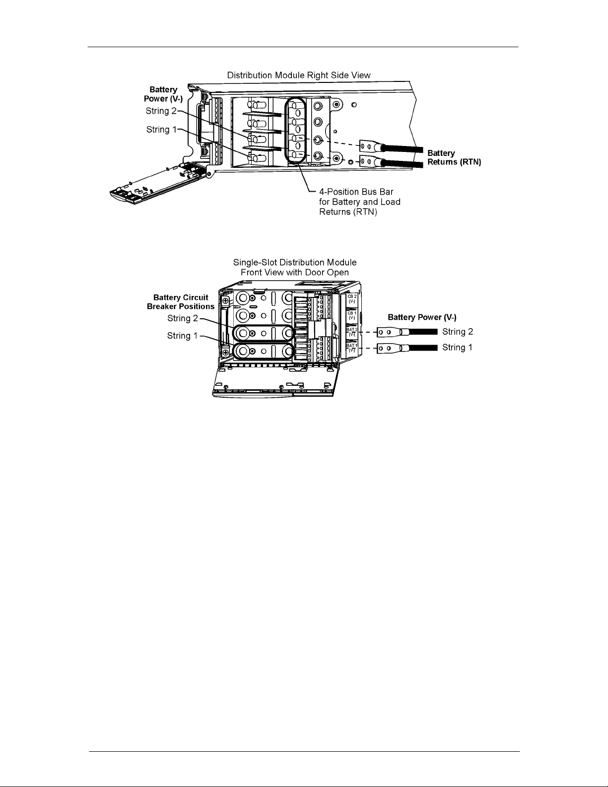
CPS6000 –48V Indoor/Outdoor Power Shelf
Figure 5-19d: Battery String Connections – Single-Slot, 10 GMT Fuses
Issue 21 January 2008 65
Page 66

CPS6000 –48V Indoor/Outdoor Power Shelf
Figure 5-19e: Battery String Connections – Double-Slot
Issue 21 January 2008 66
Page 67

CPS6000 –48V Indoor/Outdoor Power Shelf
Load Connections
Loads can be connected using 2 bullet-style circuit breakers, GMT fuses or Direct Bus
Connections.
Double-Slot Distribution Module Note
Check if Double-Slot Distribution Module positions can be used for load positions, make
connections as described here. Positions are converted from battery to a load positions using
an adapter on the circuit breaker. This is described in the section, “Installing Circuit Breakers
and Fuses.”
Terminate Load Connections - Bullet-Style Circuit Breakers
Two Circuit Breakers can be installed in the top two positions in the Distribution Module.
The load terminals on the circuit breakers can secure cabling from 18 AWG (1mm2) to No. 2
AWG (33mm2).
Step Action
1. Insert Load breakers in the top two positions in the Distribution Module.
2. Terminate the load cables on the load buss with M6 nuts and torque to 65 in-lb
(7.3Nm). See Appropriate Figures 5-20a, through 5-20c for Distribution
Module connections.
Issue 21 January 2008 67
Page 68

CPS6000 –48V Indoor/Outdoor Power Shelf
Figure 5-20a: Rear Load Connections
Figure 5-20b: Front Load Connections – Single-Slot, 5 GMT Fuses
Issue 21 January 2008 68
Page 69

CPS6000 –48V Indoor/Outdoor Power Shelf
Figure 5-20c: Front Load Connections – Single-Slot, 10 GMT Fuses; Double-Slot
Issue 21 January 2008 69
Page 70

CPS6000 –48V Indoor/Outdoor Power Shelf
Terminate Load Connections - GMT Fuses
Single-Slot Distribution
When using 20 A fuses adjacent fuse positions must be left open. No more than 80A may be
carried through the 10 fuse positions, or 40A per half-section. Up to 14 AWG wire can be
used to connect loads to each of the fuse positions. See Figure 5-21 for fuse position and
terminal block designations.
Double-Slot Distribution
The 16 GMT fuse position terminal blocks will accommodate 10 AWG wire. Each fuse board
(A and B) has 8 GMT positions and is sized to handle up to 80A of total current and can
support up to four 20 amp fuses if spaced properly. If 20A fuses are used, then adjacent fuse
positions must be left empty. See Figure 5-22 for fuse position and terminal block
designations.
Step Action
1. Strip 0.24 inches (0.6cm) of insulation from the wire.
2. Insert the stripped wire through the side of the shelf and into the screw
terminal. Torque to 4.5 in. lbs (0.5 Nm). See Figure 5-21 for Single-Slot, and
Figure 5-22 for Double-Slot Distribution Modules.
Issue 21 January 2008 70
Page 71

CPS6000 –48V Indoor/Outdoor Power Shelf
Figure 5-21: GMT Fuse Connections, Single-Slot Distribution Module
Issue 21 January 2008 71
Page 72

CPS6000 –48V Indoor/Outdoor Power Shelf
Figure 5-22: GMT Fuse Connections, Double-Slot Distribution Module
Issue 21 January 2008 72
Page 73
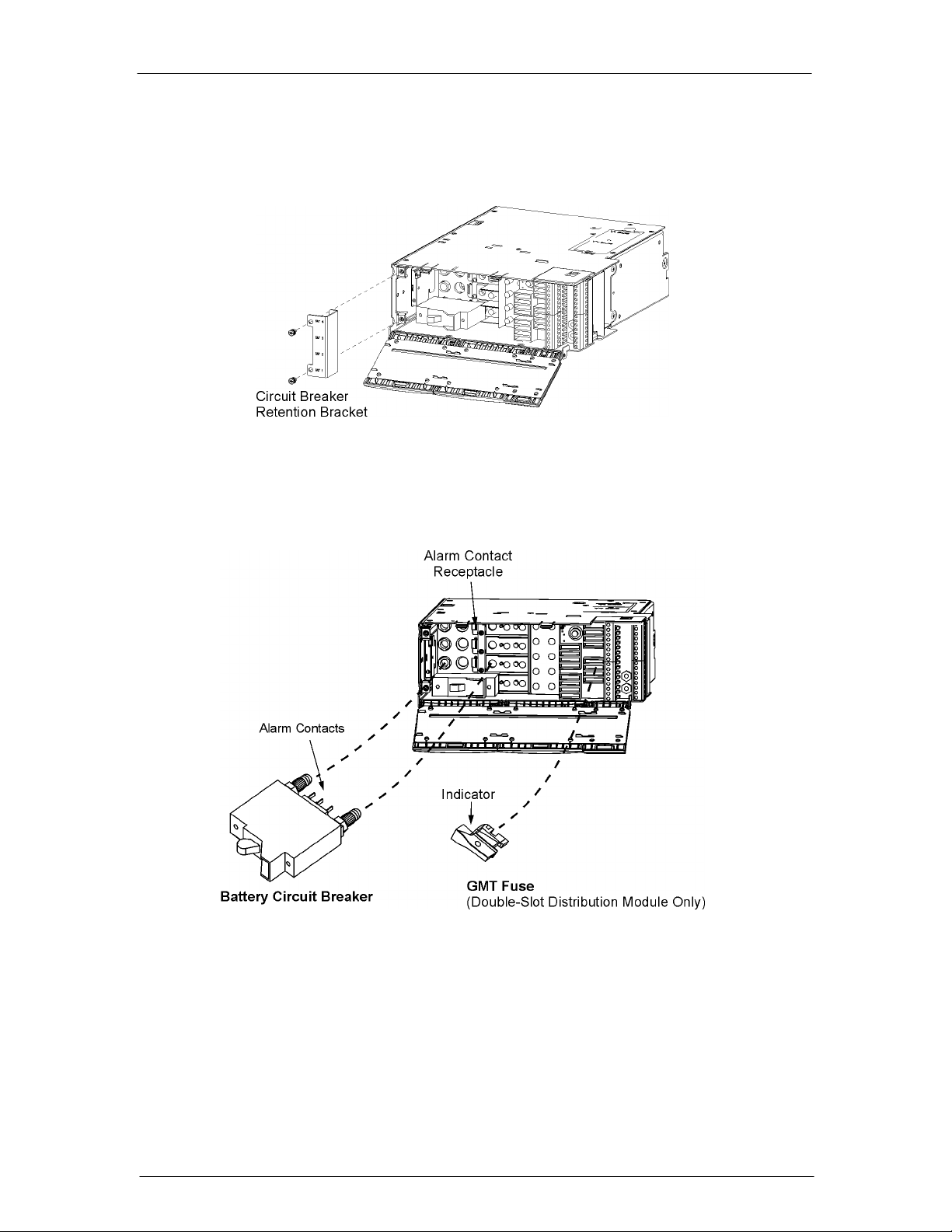
CPS6000 –48V Indoor/Outdoor Power Shelf
Circuit Breaker and Fuse Installation
Figure 5-23 and 5-24shows the proper circuit breaker and fuse orientation for installation.
Retention bracket may or may not be provided with all configurations.
Figure 5-23: Circuit Breaker Retention Bracket
Figure 5-24: Circuit Breaker and Fuse Installation
Issue 21 January 2008 73
Page 74

CPS6000 –48V Indoor/Outdoor Power Shelf
Terminate Load Connections - Direct to Bus Connections
The Distribution Module can be connected directly to the unprotected (no fuses or circuit
breakers) dc output bus. Connections are made from the top of the unit. Lug covers are not
provided they must be ordered separately.
Warning: Cables terminated directly to the DC output bus in Figure 5-25 are unfused. Ensure
cables ends are protected before terminating cables.
Step Action
1. Terminate 45° lugs (with 1/4-inch holes on 5/8-inch centers) to bus landings
(hot spots) and torque M6 screws to 65 in-lbs. (7.3Nm).
2. Break tabs off back of lug cover (see Figure 5-25).
3. Insert the front post of the lug cover into the mounting hold and snap the tab
on the back of the lug cover into place.
Figure 5-25: Direct Connection to V+ (shown) / V- Output Bus
Issue 21 January 2008 74
Page 75

CPS6000 –48V Indoor/Outdoor Power Shelf
Load Connections - Bulk Output
Bulk Output Distribution Option
Load connections are made to the Bulk Output Distribution Module as shown in Figures 526a or 5-26b or 5-26C
Figure 5-26a: Front Bulk Output Load Connections – up to 2Awg
Figure 5-26b: Large Cable (1Awg) Bulk Output Load Connections
Issue 21 January 2008 75
Page 76

CPS6000 –48V Indoor/Outdoor Power Shelf
Figure 5-26c: Rear Bulk Output Load Connections
Battery and Load Connections - External DC Distribution Panel
Battery Cable Connection
Dress battery cables internal to the equipment frame up the right side of the frame to enter the
top of a Group 163 distribution panel of H5694720 arranged for battery input.
Group 163 distribution panels are typically factory configured with four positions for battery
input and eighteen positions configured for load outputs.
Figure 5-27: Distribution Factory Configuration
Issue 21 January 2008 76
Page 77

CPS6000 –48V Indoor/Outdoor Power Shelf
Configure Additional Battery Inputs (optional)
Configure the distribution panel for the additional battery inputs as required, in groups of
four.
Step Action
1. Remove breaker terminal posts in groups of four.
2. Install busbars.
3. Remove jumpers and reinstall as shown to separate the alarm contacts between
the battery input and load output sections.
4.
If optional internal battery switches are required:
Install 1, 2, or 3 pole battery switches as required to match battery discharge
current. Make sure switch is down, in the OFF position.
If optional internal battery switches are not required:
Install no-switch jumper busses as required.
5. Using a voltmeter, verify polarity of the battery cables.
6. Attach the POSITIVE cable to the RTN bus position in line with the switch.
7. Attach the NEGATIVE cable to the busbar directly above the switch.
8. Using a voltmeter, verify polarity of the battery connection between the RTN
and battery input bus.
9. Leave the switch in the OFF position until the unit is ready to be energized.
Figure 5-28: Remove Circuit Breaker Terminal Posts
Issue 21 January 2008 77
Page 78

CPS6000 –48V Indoor/Outdoor Power Shelf
Figure 5-29: Install 4-String Battery Busbar
Figure 5-30: Relocate Alarm Jumper
Issue 21 January 2008 78
Page 79

CPS6000 –48V Indoor/Outdoor Power Shelf
Figure 5-31: Jumper Locations in Completed 8-Position Configuration
Issue 21 January 2008 79
Page 80

CPS6000 –48V Indoor/Outdoor Power Shelf
Figure 5-32: Battery and Load Connections to Distribution Panel
Issue 21 January 2008 80
Page 81

CPS6000 –48V Indoor/Outdoor Power Shelf
Bullet Style Circuit Breakers
Comcode Amperage CB Positions Min Wire Gauge
407998137 3 1 10
407998145 5 1 10
407998152 10 1 10
407998160 15 1 10
407998178 16 1 10
407998186 20 1 10
407998194 25 1 10
407998202 30 1 10
408213486 40 1 10
407998210 45 1 8
407998228 50 1 8
407998236 60 1 6
407998244 70 1 6
407998251 80 1 4
407998269 90 1 4
407998277 100 1 2
408185353 125 2 2
408185346 150 2 1/0
408564941 200 3 2/0
408535752 250 3 4/0
Issue 21 January 2008 81
Page 82

CPS6000 –48V Indoor/Outdoor Power Shelf
Initial Start-up
The system is ready to be powered up. Please verify all connections are as described prior to
applying ac power.
Step Action
1. If using battery disconnect switches place them in their ON/CLOSED
positions prior to applying ac power.
2. Turn on the ac service circuit breakers to apply power to the CPS6000 power
system.
3. Verify that All LEDs on all components including rectifiers, controllers, LVD
boards, and remote voltage monitor modules are green.
4. Verify that the reading on the controller display is 54.5 Vdc. Note that if the
connected batteries are not fully charged, the voltage may be lower. If
possible, open the external disconnect switches or activate the disconnect
switches in the Distribution Module prior to making measurements.
5. If the conditions in Steps 3 and 4 are not met refer to Section 13,
Troubleshooting.
6. Refer to Section 6 for changing system parameters from the default settings if
required (float voltages, alarm thresholds, controller settings, etc.)
7. For QS841A only :
If network parameters have been obtained from the corporate network
administrator and the controller is ready to be configured for network
operations follow the steps below: Otherwise the installation is complete.
The following Network Configuration Parameters must be obtained
from your Network Administrator before starting:
• IP address
• Subnet mask
• Host name
• Gateway IP address
Note: Host and Gateway may be optional.
Configuration of the network parameters may be done in one of two different
ways:
(1) Easy View
(2) Serial Port
8 Configuring the network parameters for QS841A only :
Using EasyView
Using a PC with EasyView running connected to J3 of the QS841A go to
Configure
parameters and click “OK” to save.
Æ
Port Communications Æ Network Port 1. Enter all network
Issue 21 January 2008 82
Page 83

CPS6000 –48V Indoor/Outdoor Power Shelf
Serial Port
The appropriate IP address, subnet mask, hostname, and default gateway IP
address must be configured on the QS841A through serial port J3.
To login to the QS841A, follow these steps:
a. Start-up the PC terminal program (Windows Terminal,
ProComm, etc.) using the following communication
parameters:
Baud : 9600
Data : 8
Parity : none
Stop : 1
Handshaking: none
Flow Control: none
b. Connect the PC to the QS841A local port (RS-232) connector
J3
c. Wait for any diagnostic messages to pass.
d. Wait for the “ENTER PASSWORD:” command line prompt.
e. Type the Network Administrator password (default:
administrator).
f.
Wait for the “$” prompt.
8A Configuring Static Network Parameters
After a valid password entry, a login header with the following format similar
to that below will be displayed:
Board Code QS841A
Serial Number 05DJ09112345
Boot Block version 1.0
Application Code version 1.0
Default Web Pages version 1.0
Custom Web Pages not found
Ethernet Address 00-60-1D-00-5C-07
IP Address not configured
Subnet Mask not configured
Default Gateway not configured
Host Name not configured
For assistance type help
$
Typing HELP at the “$” will show all available network administration
commands and command line formats.
*note: 1) commands are not case sensitive
2) for the commands that follow, ddd is a number from 0 – 255
• To set the IP Address, type:
Issue 21 January 2008 83
Page 84

CPS6000 –48V Indoor/Outdoor Power Shelf
CHA NET1,IP=ddd.ddd.ddd.ddd
Verify by typing:
STA NET1,IP
• To set the Subnet mask, type:
CHA NET1,SUB=ddd.ddd.ddd.ddd
Verify by typing:
STA NET1,SUB
• Optional:
To set the Default Gateway Address, type:
CHA NET1,GTWY=ddd.ddd.ddd.ddd
Verify by typing:
STA NET1,GTWY
•
Optional:
To set the Host Name, type:
CHA NET1,HOST=“hostname”
Verify by typing:
STA NET1,HOST
8B Logging out of the QS841A MCU.
To terminate the configuration session, enter the “bye” command. The
QS841A will notify the user if configuration is not complete. This message
will have the following format:
NOTICE:
Default Gateway may be required for network access.
Host Name may be required for network access.
Logging off...
Messages referencing the Gateway and Host Name are acceptable, since these
parameters are optional.
Note: If the IP address or Subnet mask messages appear, for example:
IP Address is required for network access.
Subnet mask is required for network access.
Then the configuration procedure must be repeated.
8C Post Installation Procedure.
Once configuration has been completed
g. Disconnect the PC from the QS841A local port (RS-232)
connector J3.
h. After approximately one minute, observe the LEDs on the J3
network connector:
• Green - STATUS LED: ON
• Yellow - Link / Active LED: ON
The QS841A should be communicating over the network.
Issue 21 January 2008 84
Page 85
CPS6000 –48V Indoor/Outdoor Power Shelf
6 AC, Alarm, and Control Cable
Reference Information
Overview
This section contains additional information (connector pin designations, etc.) that may be
required for making, customizing, or troubleshooting system connections.
AC Utility Connection
Note: Each ac connection to the CPS6000 shelf is to be provided with circuit breaker
protection at maximum 40A for a 23-inch shelf with dual ac feed and low-line (120V) input.
For high-line (200-240V) input, a 40A circuit breaker is adequate.
CAUTION: Ensure ac power is OFF to the CPS6000 system before continuing with ac
utility connection.
The 23-inch dual-feed shelf requires the H569-470 G50A ac cord, which consists of two sets
and is unterminated at the utility end. Insert these into the ac receptacles on the CPS6000
shelf. Terminate the other end with an appropriate plug. Follow all safety rules provided with
the plug when connecting the plug to the cable assembly. Refer to the following table for ac
feed polarity.
AC Voltage
120V 200 to 240V Cable Color Code Cable Color Code
Line 1 Line 1 Black Brown
Neutral Line 2 / Neutral White Blue
Ground Ground Green Green / Yellow
Guide the utility end of the ac cords to the utility source. When routing cable, please ensure
cable does not traverse any sharp or rough surfaces that may over time cause its insulation to
abrade. Also, please be careful to route cables away from doors and the like to prevent any
possible damage from pinching.
When connecting to utility source, ensure all local and national wiring rules are being
complied with.
Issue 21 January 2008 85
Page 86

CPS6000 –48V Indoor/Outdoor Power Shelf
Controller Connections
Figure 6-1 shows the Controller connector locations.
Figure 6-1: Controller Connectors for QS840 and QS841A
Shelf Paralleling Connector
J2 is a 4-pin connector provided on the controller for paralleling up to three additional
shelves. This connector is accessible when the controller is inserted in the shelf. Two of the
lines on the connector are used for inter-shelf RS-485 communication (RS485+, RS485-), two
for shelf addressing, and one for the current share for rectifiers and one for V-. Pin
assignments for this connector are shown in the following table:
Pin Signal Description
1 RS485+ RS-485 GP communication bus
2 RS485- RS-485 GP communication bus
3 RECT_PG_EN Programming enable signal to rectifier (future use)
4 ISHARE Rectifier analog current share
Auxiliary Port Connector
An RJ-45 receptacle (P5) is provided on the QS840A/QS841A board for connecting to the
QS773X VT-Probes or to the QS771A Remote Voltage Monitor. This connector is accessible
when the controller is inserted in the shelf. The signals and pin assignments for this interface
are shown in the following table:
Issue 21 January 2008 86
Page 87

CPS6000 –48V Indoor/Outdoor Power Shelf
Pin Signal Description
1 RS-485 + RS485 GP communication bus
2 RS-485 - RS485 GP communication bus
3 SIG_RTN Protected signal return for RS485 and 1-wire
4
5 1-Wire 1-wire communication signal
6 +5V Protected +5V Power
7
8
Local RS232 Serial Port Connector
A DB-9 connector (J3) with a male housing and female pins supporting a local RS-232 port
with a subset of handshake signals is provided for local terminal access. This connector
provides an isolated RS-232 communication port for notebook computers and PCs.
The local port pin assignments should take the assignment as a Data Circuit-terminating
Equipment (DCE). This assignment is shown in the following table.
Pin Signal Description
1 RS-232 DCD *RS-232 Data Carrier Detect (output)
2 RS-232 TXD RS-232 Transmit (output)
3 RS-232 RXD RS-232 Receive (input)
4 RS-232 DSR RS-232 Data Set Ready (input)
5 RS-232 ISO GND RS-232 Isolated Ground
6 RS-232 DTR *RS-232 Data Terminal Ready (output)
7 RS-232 CTS RS-232 Clear To Send (input)
8 RS-232 RTS RS-232 Request To Send (output)
9 NC No Connect
* These signals are not necessary for supporting a local port connection.
LAN Connection (Ethernet)
A standard integrated RJ-45 receptacle (P6) is provided on the QS841A for connecting to an
appropriate 10/100 Base-T LAN. P6 is shielded with the shield being tied to chassis. This
connector is accessible when the controller is inserted in the shelf. The signals and pin
assignments for this interface follow industry standard and are shown in the following table:
Pin Signal Description
1 TX+ Tranceive Data+
2 TX- Tranceive Data3 RX+ Receive Data+
4 n/c Not connected
5 n/c Not connected
6 RX- Receive Data7 n/c Not connected
8 n/c Not connected
Issue 21 January 2008 87
Page 88
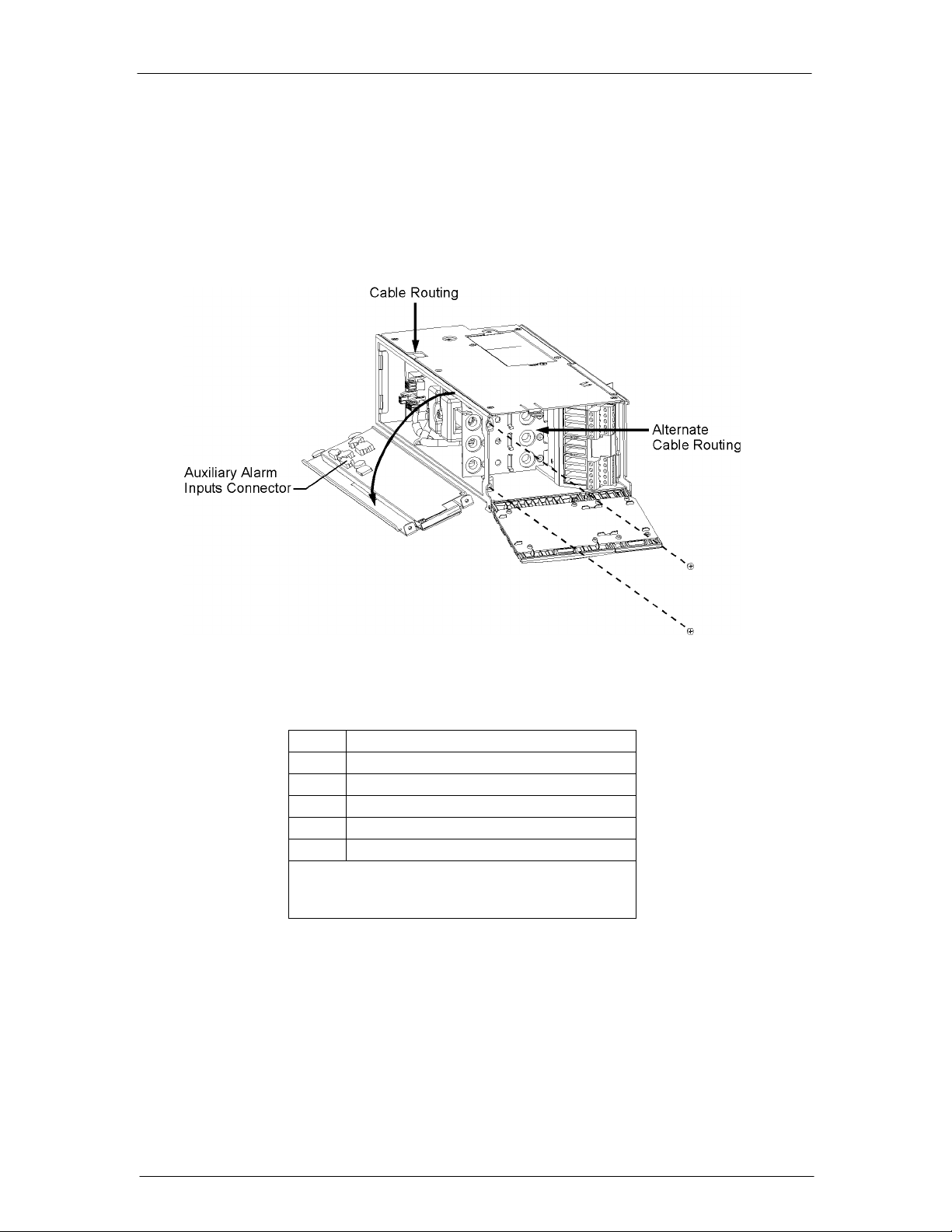
CPS6000 –48V Indoor/Outdoor Power Shelf
Auxiliary Alarms
Distribution Module
Four auxiliary alarm inputs are provided, auxiliary inputs 1 through 4, and are configurable
through RS-232 interface of the controller. Auxiliary alarm inputs can be made on the AMM
board. Remove the Distribution Module side cover and AMM board for access to the
connector as shown. The auxiliary alarm input connector pin assignments are shown below.
Figure 6-2: P5 Auxiliary Alarms Connector
Pin
*Alarms are generated by connecting alarm contact
inputs to Vminus, typically through a clean relay
contact from the monitored device.
Alarm*
1 Auxiliary 1
2 Auxiliary 2
3 Auxiliary 3
4 Auxiliary 4
5 Return (Vminus/Battery)
Mating connector information for this 4-pin connector is as follows:
Housing: Amp part number 1445022-4
Contact (on a strip): Amp part number 794606-2
Contact (loose piece): Amp part number 794610-2
Issue 21 January 2008 88
Page 89

CPS6000 –48V Indoor/Outdoor Power Shelf
Bulk Output Module
A fuse alarm input for monitoring an external distribution is available on the Bulk Output
Module on connector J3, pin 1 (Figure 6-3).
Figure 6-3: Bulk Output Module Connectors
The input can be connected to a relay which provides system voltage on alarm. Pin 2 (V-) can
be used to provide system voltage with a clean relay contact.
Additional Bulk Output Module Connections
Vsense-, Vsense+
Pins 1 and 2 (Vsense- and Vsense+) on J2 are wired to monitor system voltage internal to the
Bulk Output Module. To monitor system voltage externally, unplug the mating connector
from J2 and connect Vsense- and Vsense+ to the external source to be monitored.
Issue 21 January 2008 89
Page 90

CPS6000 –48V Indoor/Outdoor Power Shelf
7A QS840A System Controller
Overview
The QS840A Controller provides system monitoring and control features, as well as office
alarm outputs from rectifiers, LVD boards, and remote modules. This section describes the
controller features, functions and alarms.
Controls and Display
Figure 7-1 shows the front panel controls and display of the controller.
Figure 7-1: QS840A Controller Faceplate
The backlight of the four-line LCD display changes color to reflect the system alarm status as
follows:
Green Normal
Amber Minor Alarms Present
Red Major Alarms Active
The up and down arrow keys can be used to adjust screen contrast when the controller is
displaying the default screen. Contrast adjustment is also available through the menus at
Menu>Configuration>System Settings. At the default menu, the left and right arrows are also
used to toggle the display from displaying the system voltage or the system load current.
Otherwise, the left and right arrow keys are used to navigate the menus and the up and down
arrow keys are used to change values when configuring the system. A black box highlighting
a menu item indicates that the item has sub-menus.
Issue 21 January 2008 90
Page 91

CPS6000 –48V Indoor/Outdoor Power Shelf
Connectors
Figure 7-2 shows a side view of the controller unit.
Figure 7-2: QS840A Controller Unit Side View
An isolated RS-232 connector (J3) is provided for local access or for connection to an
external modem. The software interface is compatible with Lineage Power EasyView for
Windows GUI software for PCs. Software support is also provided for use with Lineage
Power Galaxy Manager for web-based remote access and monitoring.
The controller also includes six alarm relays. Two are pre-assigned as power Major and
power Minor alarm relays. The four remaining relays are available as user-definable alarms
and have been predefined for the various QS840A configurations.
Software
The software is functionally divided on the Main Menu into the following categories:
Alarms
Warnings
Status
Control/Operations
History
Configuration
The following figures show a map view of each category and the settings and operations
found in each, and are followed by brief descriptions of the menu items. Alarms and
Warnings are not hierarchal mapped and are presented in chronological order of occurrence
when they are present. “No Active Alarms” or “No Active Warnings” will be displayed when
they are no alarms or warnings detected by the controller.
Figures 7-3a through 7-3d provide a menu flow map of the QS840A controller software
followed by brief descriptions of the menu items. Older or customer controller may have only
some of the described menu items
Issue 21 January 2008 91
Page 92

CPS6000 –48V Indoor/Outdoor Power Shelf
Figure 7-3a: Software Menu Map
Issue 21 January 2008 92
Page 93

CPS6000 –48V Indoor/Outdoor Power Shelf
Figure 7-3b: Control / Operations and History Menus
Issue 21 January 2008 93
Page 94

CPS6000 –48V Indoor/Outdoor Power Shelf
Figure 7-3c: Configuration Menu (part 1)
Issue 21 January 2008 94
Page 95

CPS6000 –48V Indoor/Outdoor Power Shelf
Figure 7-3d: Configuration Menu (part 2)
Issue 21 January 2008 95
Page 96

CPS6000 –48V Indoor/Outdoor Power Shelf
CPS6000 Controller Minimum Configuration
General Information
QS840A is the nerve center of the CPS6000 Battery Plant. The controller has six alarm
relays; Two are pre-assigned as power major and power minor alarms. The four remaining
relays are available as user-definable alarms to external devices.
QS840A
• Provides system monitoring and control features
• Controls alarm reporting from rectifiers, Low Voltage Disconnects (LVD), and other
system components.
User Interface and Display
Overview
QS840Aís primary user interface is a front panel display which includes the following:
• An array of simple push-button controls
• A backlit four-line LCD display that changes color to reflect the system alarm status as
follows:
Green Normal
Amber Minor Alarms Present
Red Major Alarms Active
Minimum Configuration
The Controller has many configurable parameters. All parameters are discussed in this
section. The following steps cover the minimum configuration.
Key Description Function
Display Menu
Up and Down Arrows
Left and Right Arrows
Previous Menu
Press to access the menu. Display Menus, Refresh, Save
Changes
Press to adjust values when configuring the system
parameters. Also used to adjust screen contrast when the
controller default screen is displayed.
Press to select the digit to adjust and navigate the menus.
Press to back up to a previous menu.
Issue 21 January 2008 96
Page 97
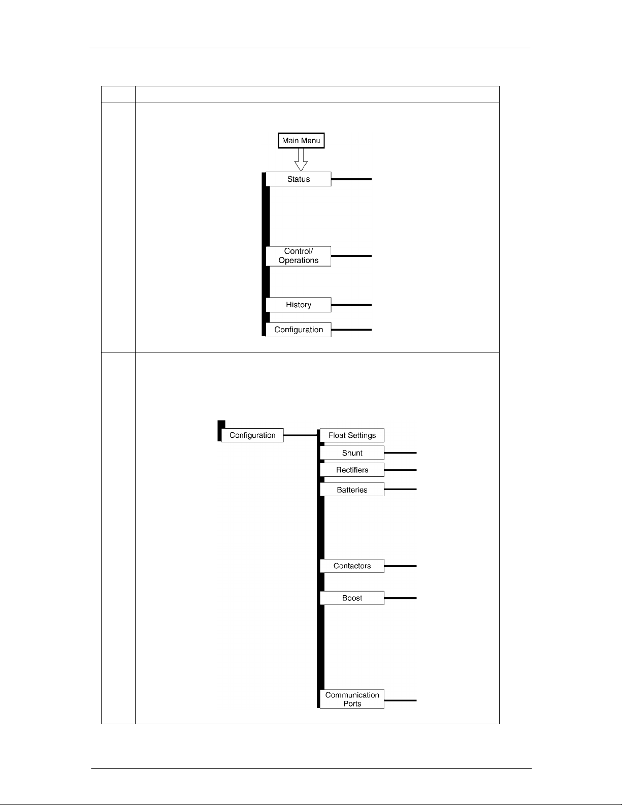
CPS6000 –48V Indoor/Outdoor Power Shelf
Step Action
1. From the default screen, press the Display Menu key to see the Main Menu.
2. Press the down arrow key until Configuration is highlighted, press the
Display Menu key and the following selections are available; Float settings,
Shunt rating, Rectifier Redundancy, Batteries, Contactors, Boost, System
Settings, and Communication Ports.
Issue 21 January 2008 97
Page 98

CPS6000 –48V Indoor/Outdoor Power Shelf
3. The Float Settings option will be highlighted, press the Display Menu key to
access the Float Settings Menu.
4. The Set Point option will be highlighted. Press the Display Menu key to view
or change the Float voltage Set Point. Use the left and right arrow keys to
adjust the Set Point voltage. Once the Voltage has been set to the desired
value Press the Display Menu key to save the change. The voltage range is
42.0 to 56.5 Volts. Factory default is -54.5V.
5. Select Voltage Alarms to set the four Voltage Alarm thresholds.
Alarm Description
Very High Voltage
Major
High Voltage
Minor
BD (Battery on Discharge)
Major
Very Low Voltage
Major
Alarm occurs and the unit is shut down when the system
detects voltage above its set threshold. The threshold can be set
from 50V to 60V in 1V increments. The factory default setting
is 57V
Alarm indicates an abnormally high output voltage but does
not shut the unit down. The alarm threshold can be set from
50V to 60V in 1V increments. The factory default setting is
56V.
Alarm occurs when the system is operating either completely
or partially on battery power. The alarm threshold can be set
from 46V to 55V in 0.1V increments. The factory default
setting is 51.0V.
Alarm indicates an imminent system shutdown due to
discharging batteries or low output voltage. Factory default -
46.0V.
Note: Factory defaults listed are for the standard QS840A controller.
Status
This area of the menu provides an overview of system threshold settings, equipment
operation, and present component values. Only state type information is available in this
menu. No configuration or operations are possible from the Status portion of the menu
system. Following are the elements available in the Status menu.
Rectifiers: Total installed capacity of the system, total output current of all rectifiers, and the
individual rectifier currents by rectifier number (Gnn).
Issue 21 January 2008 98
Page 99

CPS6000 –48V Indoor/Outdoor Power Shelf
Batteries: The following battery management information is available under Status:
Installed Capacity User entered system battery capacity in AH. Automatically entered
when using smart Lithium batteries.
On-Line Capacity Available battery reserve from installed capacity value directly
connected to the bus. It is always the same value configured for
installed capacity except for when the smart lithium batteries are
utilized.
Current Current flowing into or out of the batteries.
Number Of Strings The total number of battery strings installed in the system.
Highest Temp Highest battery temperature being measured by the thermal probes.
Temp Probes Number of installed thermal probes.
Mid-Cell Volts Number of installed Mid-cell voltage measurement modules.
Battery Test Result Shows whether the most recent battery test was completed, and the
reserve time.
Next Test The date of the next automatic battery discharge test. The automatic
discharge test feature must be enabled for this to work.
Live Reserve Time Present value of battery reserve time calculated by the controller
Shunt Currents:
A maximum of six measured currents from each Distribution Control
and Monitoring module present in the system is displayed.
Disconnect States: The status of the LVBD (Low Voltage Battery Disconnect) and
LVLD1-3 (Low Voltage Load) disconnects are displayed. “None” is displayed if
there are no contactors in the system.
Alarm Thresholds: Present alarm threshold settings in xx.xV format of the following system
alarms:
Float Voltage
Alarms
Boost Voltage
Alarms
High Batt Temp Highest temperature being measured by the thermal probes
Reserve Low Low battery reserve time
High Ambient Temp High ambient temperature
Low Ambient Temp Low ambient temperature
Ringer Thresholds: Present status of up to two ringer chassis:
State Ringer chassis present or not
VA Output VA of ringer
Primary Ringer module present in primary position
Secondary Ringer module present in secondary/redundant position
Very High Major, Very High Minor, BD Major and Very Low
Major
Very High Major and High Minor
Issue 21 January 2008 99
Page 100

CPS6000 –48V Indoor/Outdoor Power Shelf
Enable-Disable Info: Displays the enable/disable status of the following features:
Temp Comp Temperature compensation
Low Temp Comp Low temperature compensation
Recharge Ilim Recharge current limit
Auto Boost Automatic boost charge
Auto Batt Test Automatic battery test
Rect Redund Rectifier redundancy
Mid-Cell V Mon Mid-cell voltage monitoring
Imminent Shutdn Imminent system shutdown alarm (LVBD)
Local Write Whether or not the system can be configured through the local port.
Modem Write Whether or not the system can be configured through the modem port.
System Info: Various high level system statuses.
Controller Info Provides the versions of software for the overall controller
(QS840A_MC1), boot block of the controller, display, and the defaults.
Date System controller present date using configured format.
Time System controller present time using configured format.
Ambient Temperature System controller present temperature using configured format.
Control/Operations
The following are the system control and operation functions that can be performed from the
front panel. These operations are generally used in post installation and maintenance modes.
Start Lamp Test Temporarily illuminates all status indicators of attached rectifiers,
distribution monitoring and control modules and the system
controller.
Restart Rectifiers Restarts all system serial controlled rectifiers. Does not affect
rectifiers, and other system devices that are already functioning.
Clear Events Used to clear momentary events or alarms. It clears the following
system alarms: Check Battery, Reserve Time Low, Battery
Voltage Imbalance
Uninstall Equipment Clears alarms related to the removal of a system component such
as a rectifier, thermal probe, or voltage monitoring module.
Alarm Test Initiates the asserting the Form-C alarms.
Start Battery Test Initiates the manual battery test feature. A stop battery test
operation is displayed to interrupt the testing and return the unit to
normal operation. The manual battery test utilizes the configured
test duration and a system bus voltage threshold to represent the
end of reserve.
Start Boost
Initiates the manual battery Boost feature. A stop battery Boost
operation is displayed to interrupt the Boost operation mode and
return the unit to normal operation.
Issue 21 January 2008 100
 Loading...