

Page 1

CPS2500D +/-190V
Downstream System
Product Manual
Select Code 167-102-106
Comcode 848755265
Issue 4
January 2008
Page 2

Page 3

Product Manual
Select Code 167-102-106
Comcode 848755265
Issue 4
January 2008
CPS2500D +/-190V
Downstream System
Notice:
The information, specifications, and procedures in this manual are
subject to change without notice. Lineage Power assumes no
responsibility for any errors that may appear in this document.
© 2008 Lineage Power
All International Rights Reserved
Printed in U.S.A.
Page 4

Page 5

CPS2500D +/-190V Downstream System
Table of Contents
1 Introduction
CPS2500D Downstream System 1-1
Overview 1-1
Applications 1-1
Web Site 1-1
Customer Service Contacts 1-2
Customer Service, Technical Support,
Product Repair and Return, and Warranty Service 1-2
Customer Training 1-2
On-Line Power Systems Product Manuals 1-2
EasyView software 1-2
2 Product Description
Physical Description 2-1
Block Diagram 2-1
Operation 2-2
Specifications 2-3
Electrical 2-4
Maximum Output Power 2-5
Installation category: 2-5
3 Engineering and Ordering
Ordering Information 3-1
Engineering 3-2
4 Safety
Safety Statements 4-1
Warning Statements and Safety Symbols 4-4
Deutsch 4-6
Espanol 4-6
5 Installation
CPS2500D Installation 5-1
Purpose 5-1
Precautions 5-1
Safety 5-1
Installation Tools 5-1
Issue 4 January 2008 Table of Contents - 1
Page 6

CPS2500D +/-190V Downstream System
Unpack the CPS2500D Shelf 5-2
CPS2500D Unpack 5-2
Ground Configuration 5-3
Ground Jumper 5-3
Inspect the Network 5-4
Check and Mark Wiring Compliance 5-4
Install the CPS2500D Shelf 5-5
CPS2500D Frame Install 5-5
CPS2500 Cable Install 5-6
Installing the Converters 5-7
QS882A Converter Installation 5-7
Install the QS882A Converters 5-7
Recognizing Normal States 5-8
Recognize Normal States 5-8
Diagnosing Abnormal States 5-9
Diagnosing Abnormal States 5-9
6 Electrical Interface Reference Information
Shelf Electrical Interfaces 6-1
Connector Details 6-1
Connector Pinouts 6-2
7 Reference Information
CPS2500D Shelf 7-1
QS882A Converter 7-3
8 Product Warranty
Appendix A Operating Temperature and Vertical Spacing
Overview A-1
Operating Temperature A-1
Revision History
2 - Table of Contents Issue 4 January 2008
Page 7

CPS2500D +/-190V Downstream System
List of Figures
Figure 1-1: CPS2500D Downstream System 1-1
Figure 2-1: QS800A Shelf Block Diagram 2-1
Figure 2-2: Unit Maximum Output Power vs. Input Voltage 2-5
Figure 3-1: Constant Delivered Power Curves
(normal range of operation) 3-2
Figure 5-1: Ground Jumper 5-3
Figure 5-2: QS800A Frame Mounting 5-5
Figure 5-3: ESD Ground Jack 5-6
Figure 5-4: QS800A with All Cables Attached 5-6
Figure 5-5: Align the QS882A Converter 5-7
Figure 5-6: QS800A with All Cables Attached 5-7
Figure 5-7: Recognizing Normal States
(with associated LED display definitions) 5-8
Figure 5-8: Output Voltage Low - Additional Circuits Required 5-9
Figure 5-9: Converter Internal Fault 5-10
Figure 5-10: Remove Converter 5-10
Figure 5-11: Network Wiring Fault 5-11
Figure 5-12: Network Wiring Faulty on Circuit 6B 5-11
Figure 5-13: Relay Identification for Replacement 5-13
Figure 7-1: QS800A Shelf Mounting Hole Dimensions 7-1
Figure 7-2: Depth and Height Dimensions 7-1
Figure 7-3: 12-Inch Shelf Mounting Hole
Dimensions (CC109139853) 7-2
Figure 7-4: Shelf Equipped with 19-Inch Adapter Bracket
(CC848828525) 7-2
Figure 7-5: Q882A Size 7-3
Issue 4 January 2008 List of Figures - 1
Page 8

Page 9

CPS2500D +/-190V Downstream System
List of Tables
Table 2-A: Absolute Maximum Ratings 2-3
Table 2-B: Electrical Specifications 2-4
Table 7-A: LED Truth Table 7-4
Issue 4 January 2008 List of Tables - 1
Page 10

Page 11
CPS2500D +/-190V Downstream System
1 Introduction
CPS2500D Downstream System
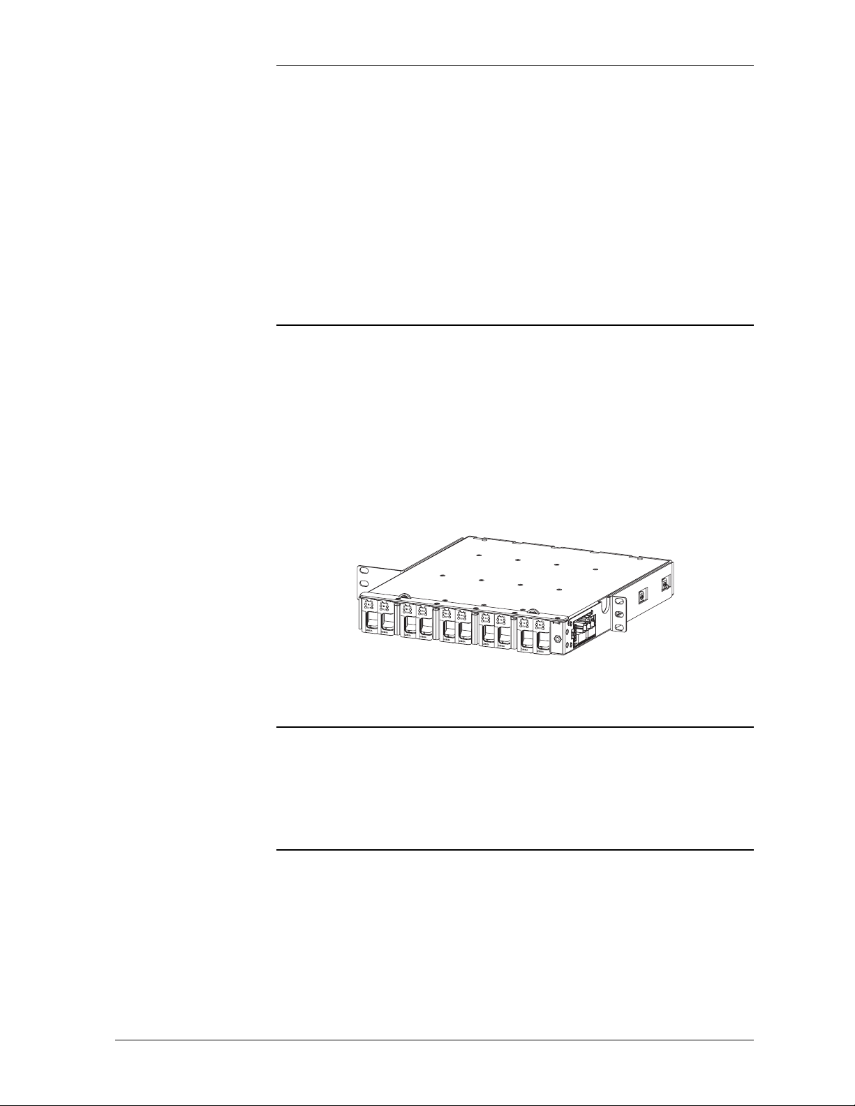
Overview The CPS 2500D System consists of up to ten QS882A dual converter cards in
a shelf with input and output wiring and an alarm and connector card on the
right side. Each converter on the QS882A card:
• Accepts 100VA limited source voltage in a range of 190 to 395 volts.
• Delivers up to 65W at nominal -48 volts.
A fully configured shelf delivers a maximum load power of 1300 Watts in an
outdoor cabinet. If converter card redundancy is desired the maximum power
that can be delivered is 1170 Watts.
Figure 1-1: CPS2500D Downstream System
Applications The CPS2500D is the part of a telephone line powered system that is located
with the video switching equipment at a site not served by batteries - typically
a cross connect cabinet. It is designed to operate most optimally from a
CPS3200U source on the other end of the telephone lines near a battery
reserve, but works with other upstream vendor equipment.
Web Site For further information about CPS6000 systems visit the CPS6000 Web site at
http://www.lineagepower.com/
Issue 4 January 2008 Introduction 1 - 1
Page 12

CPS2500D +/-190V Downstream System
Customer Service Contacts
Customer Service, Technical Support, Product Repair and Return, and Warranty Serv ice
Customer Training Lineage Power offers customer training on many Power Systems products. For
Downloads and Software
For customers in the United States, Canada, Puerto Rico, and the US Virgin
Islands, call 1-800-THE-1PWR (1-800-843-1797). This number is staffed
from 7:00 am to 5:00 pm Central Time (zone 6), Monday through Friday, on
normal business days. At other times this number is still available, but for
emergencies only. Services provided through this contact include initiating the
spare parts procurement process, ordering documents, product warranty
administration, and providing other product and service information.
For other customers worldwide the 800 number may be accessed after first
dialing the AT&T Direct country code for the country where the call is
originating, or you may contact your local field support center or your sales
representative to discuss your specific needs.
information call 1-972-284-2163. This number is answered from 8:00 a.m.
until 4:30 p.m., Central Time Zone (Zone 6), Monday through Friday.
To download the latest product information, product software and software
upgrades, visit our web site at
http://www.lineagepower.com/
1 - 2 Introduction Issue 4 January 2008
Page 13
CPS2500D +/-190V Downstream System
)
2 Product Description
Physical Description
Block Diagram
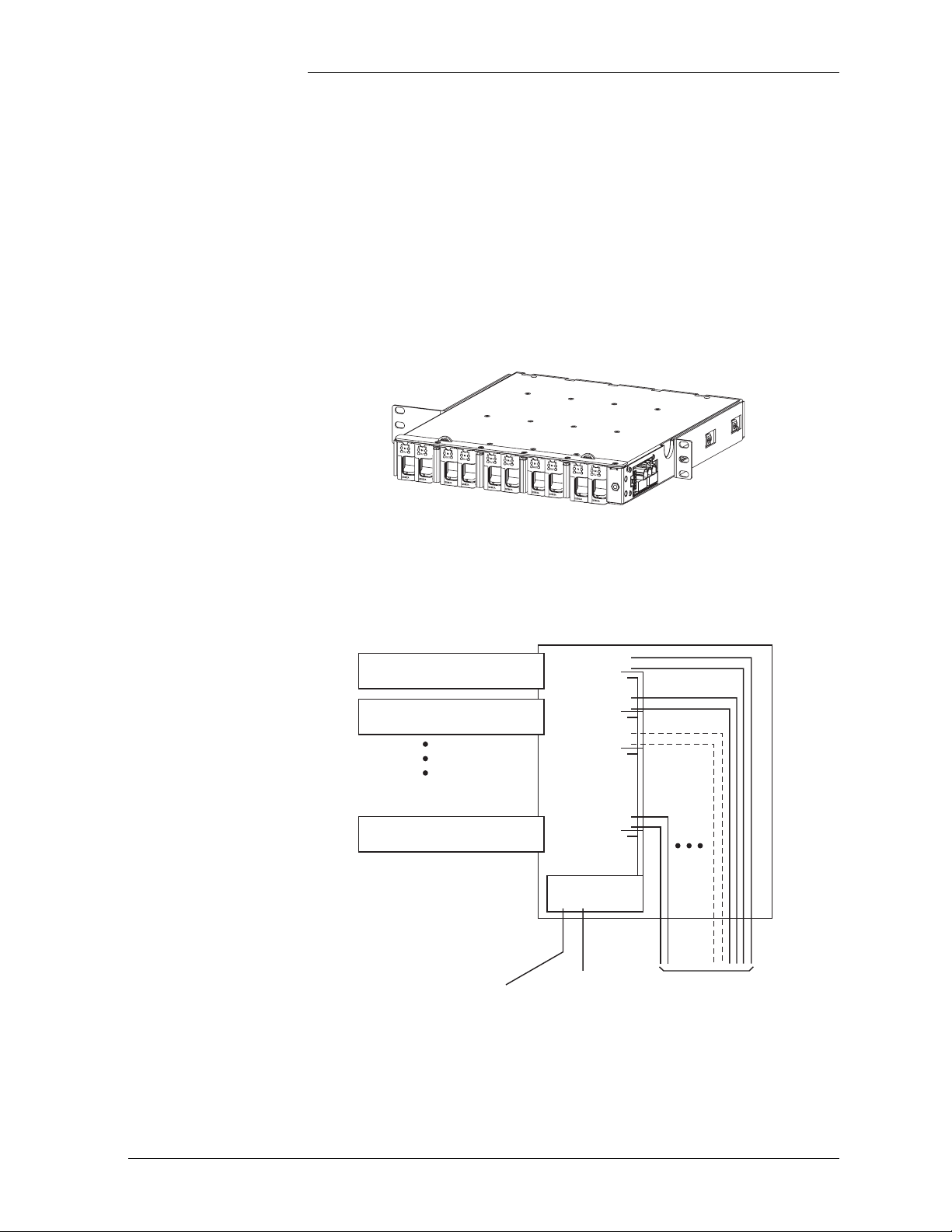
QS882A Dual Converter
QS882A Dual Converter
QS882A Dual Converter
P321
Signal Output
Cable
QS800A Shelf
Slot 1
Slot 2
Slot 10
Alarm Card
P700
-48V Output
Power Cable
P800
+/-190V Input
Power Cable
(20 Telephone Pairs
Figure 2-1: QS800A Shelf Block Diagram
Issue 4 January 2008 Product Description 2 - 1
Page 14

Operation
CPS2500D +/-190V Downstream System
Power comes in on P800 from up to 20 independent 100VA +/- 190V circuits.
Power comes out on P700 at -54 volts. Maximum current for a fully
provisioned shelf is 24 Amps or 1300 Watts. Major and minor alarms are
available on P321. The alarms are configured as Form C closures. A major
indicates circuit or input failure on 2 or more circuits. A minor alarm indicates
circuit or input failure of one circuit.
Section 5 has a step by step installation and trouble shooting process using the
Display LEDs as a primary guide to next actions.
2 - 2 Product Description Issue 4 January 2008
Page 15
Specifications
CPS2500D +/-190V Downstream System
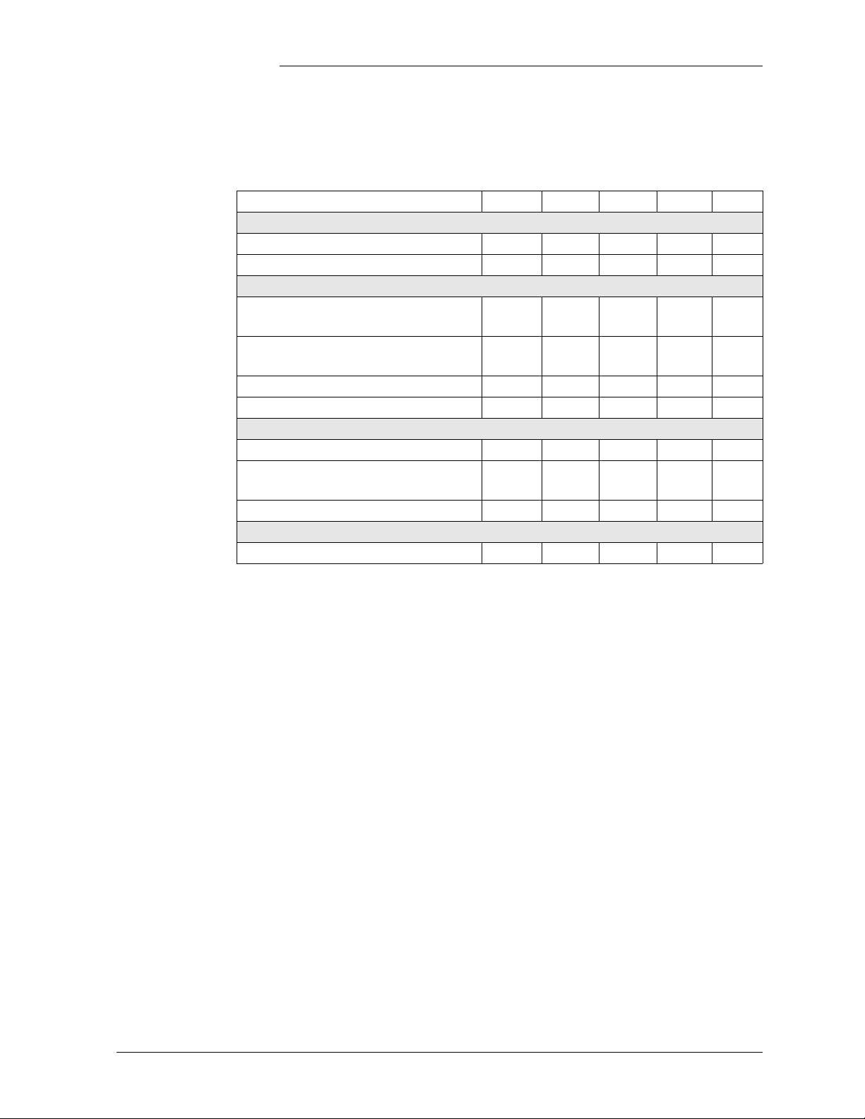
Table 2-A: Absolute Maximum Ratings
Parameter Symbol Min Typ Max Unit
Input Voltage
Continuous VI 0 380 400 Vdc
TransientDuration = 10ms Vtr 400 TBD Vdc
Te mp er at ur e
Normal Operating Ambient
Temperature at 150 lfm airflow
Operating Ambient Temperature at
higher (TBD) airflow
(See Thermal Considerations section)
Storage Temperature Tstg -55 125 °C
Power
Input Power (per Power unit) Pin 200 W
Power Dissipation (Power unit
Dissipation)
Output Power (per Power unit) Pout 130 TBD W
Isolation
Input to Output Voltage 1500 Vdc
TA -40 65 °C
TA -40 75 °C
Pdiss 27 TBD W
Issue 4 January 2008 Product Description 2 - 3
Page 16
CPS2500D +/-190V Downstream System
Electrical Unless otherwise specified, specifications apply over all operating input
voltage, output load current and temperature conditions.
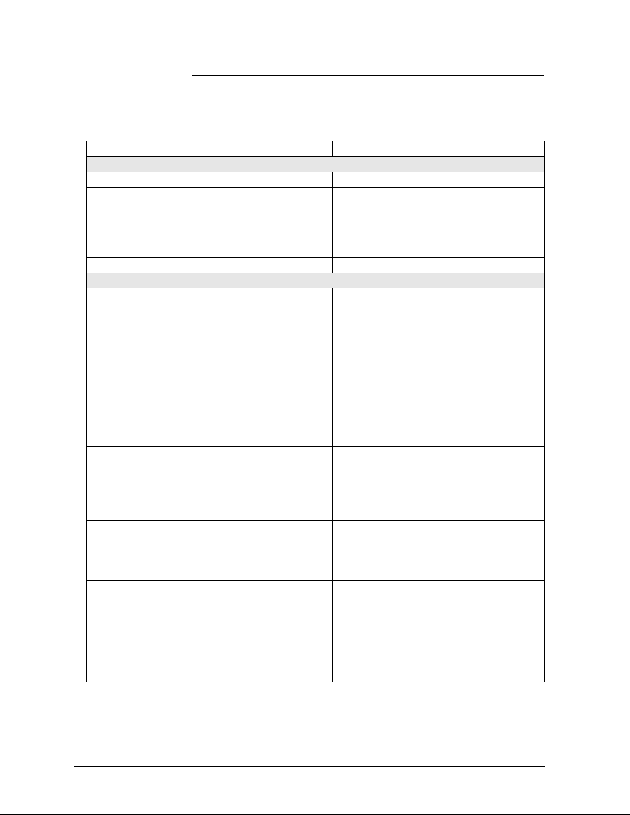
Table 2-B: Electrical Specifications
Parameter Symbol Min Typ Max Unit
Input
Operating Input Voltage Vi 130 391.1 400 Vdc
Maximum Input Current
0.233
0.241
0.250
(±190 Vdc: Vioc=320 Vdc to 398 Vdc, Io=Io, max)
Future Code:
Iin max
0.314
0.33
0.347
(±130 Vdc: Vioc=250 Vdc to 278 Vdc, Io=Io, max)
Inrush Transient (Duration: <= 1.0 ms) Ipk 0.25 Adc
Output (per Power Unit, 2 Circuits)
Output Voltage Set-point
(Vin=Vin min, Io=1.47A, Ta =25°C)
Vo , s e t -54.5 Vdc
Output Voltage
(Over all operating input voltage, resistive load, and
Vo -52.0 -- -55.0 Vdc
temperature conditions until end of life)
Output Regulation
Line (Vin=Vin min to Vin max)
Load* (Io=Io min to Io max)
--
--
0.5
TBD
--
3.5
%Vo
%Vo
*Output voltage droops as load current
increases to provide system current sharing.
Temperature (TA = -40°C to +85°C)
--
150
--
Output Ripple and Noise on nominal output
(Vin=Vin nom and Io=Io min to Io max)
RMS (5Hz to 20MHz bandwidth)
Peak-to-Peak (5Hz to 20MHz bandwidth)
--
--
140
200
--
mVrms
--
mVpk
External Capacitance Co max -- -- 3,000 µF
Output Power (per circuit pair, Vo=Vo min) Io 0 2.5 Adc
Efficiency (Io=Io max, Vo=Vo set, Ta=25°C)
Vin=260V
Vin=380V
η 86
83
%
Dynamic Load Response
(ΔIo/Δt=1A/10µs, Vin=Vin nom, Ta=25°C)
Load Change from Io=50% to 75% of Io max
Peak Deviation
Load Change from Io=75% to 50% of Io max
Peak Deviation
Vpk
ts
Vpk
ts
%Vo set
%Vo set
Settling Time (Vo<10% peak deviation)
Adc
mV
µs
µs
2 - 4 Product Description Issue 4 January 2008
Page 17
CPS2500D +/-190V Downstream System
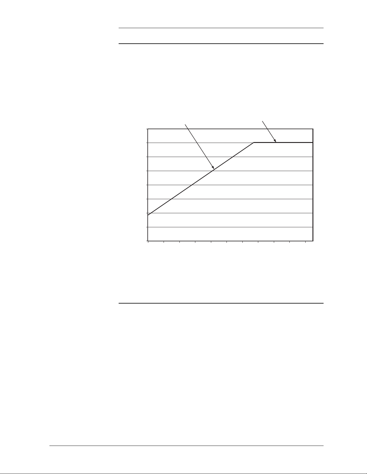
Maximum Output Power
The following graph shows the low side tolerance output power from the pair
of dc/dc circuits on each unit, as input voltage delivered to the unit varies due
to losses in the copper feeder pairs. Efficiency is assumed to be linear with 84%
at Vin minimum of 190V (Pin =2 x (190 x 0.239) = 2 x 45.41W = 90.82W),
and 83% at Vin maximum of 380V; maximum input current is limited to 0.239
Amps at all input voltages.
Output power limited by
thermal dissipation
Watts
Output power limited by
maximum input current
140.0
130.0
120.0
110.0
100.0
90.0
80.0
Installation category:
Unit Output Power (per circuit pair)
70.0
60.0
190 210 230 250 270 290 310 330 350 370 390
Input Voltage
Figure 2-2: Unit Maximum Output Power vs. Input Voltage
Unit Maximum Output Power vs. Input Voltage when fed from +/-190V
upstream source.
Input power shall be provided by up to 20 telephone wire pairs. The host
system must protect each pair to a level corresponding to a CommScope
3C*EW Gas tube primary protector. This protector has a voltage breakdown
range of 265-465 Volts and an impulse spark over range of <265-700 Volts.
Issue 4 January 2008 Product Description 2 - 5
Page 18

Page 19

CPS2500D +/-190V Downstream System
3 Engineering and Ordering
Ordering Information
Shelf Description Comcode
QS882A Converter Unit 108994918
QS800A Shelf 108994926
QS800B 12-Inch Complete Shelf (requires
external ground connection)
19-Inch Adapter Bracket CC848828525
CC109139853
Issue 4 January 2008 Engineering and Ordering 3 - 1
Page 20

Engineering
CPS2500D +/-190V Downstream System
Engineering a telephone line powered system requires knowledge about the
resistance of the input wires feeding each circuit. To make a rough estimate
follow these steps. An example follows each step in [ ] brackets.
1. Assess the total resistance of the loop feeding each circuit. [ 600Ω ]
2. Decide how much power your load requires. [ 600W ]
3. Choose the highest power curve available for circuits with the input
resistance provided by your network. [ For 600Ω, the 60Watt line almost
works. This looks like about 58 Watts.]
Figure 3-1: Constant Delivered Power Curves
(normal range of operation)
3 - 2 Engineering and Ordering Issue 4 January 2008
Page 21

CPS2500D +/-190V Downstream System
4. Use the 80% efficiency factor to determine how much power is delivered
per circuit. [58 Watts * .8 = 46.4 Watts]
5. Divide your total load by the power delivered per circuit to determine the
minimum number of circuits required to support the load. [ 600 Watts / 46.4
Watts = 12. 93 circuits or 13 circuits.]
6. Add cards to reach the level of redundancy desired. [ One card redundancy
so 16 circuits or 8 cards.]
Issue 4 January 2008 Engineering and Ordering 3 - 3
Page 22

Page 23

CPS2500D +/-190V Downstream System
4 Safety
Safety Statements
Please read and follow all safety instructions and warnings before installing,
maintaining, or repairing the system:
• The system is Underwriters Laboratories (UL) Recognized per the
applicable requirements of UL60950-1 and UL60950-21.
• For the product to be safe the chassis must be grounded by a permanent
means.
• The return conductor of the -48V shall be earthed.
• Install only in restricted access areas (dedicated equipment rooms,
equipment closets, or the like) in accordance with articles 110-31, 110-32,
and 110-33 of the U.S. National Electric Code (NEC), ANSI/NFPA No.
70, and pursuant to applicable local codes.
• The telecommunication line cable, carrying the +/-190V, shall be
minimum 26 AWG, and rated minimum 200V. Consideration shall be
taken at the time of installation to verify cable rating.
• Primary protection must be provided on all the telecommunication line
cable consistent with UL 497.
• Airflow must be provided at a rate of 150 lfm across the entire cross
section of the shelf for operation in environments from -40°C to 65°C.
• This equipment is to be used in controlled environments (an area where
the humidity is maintained at levels that cannot cause condensation on the
equipment, the contaminating dust is controlled, and the steady-state
ambient temperature is within the range specified).
• This equipment must not be installed over combustible surfaces.
• For installations in the United States, Listed compression connectors are
to be used to terminate Listed field-wired conductors where required.
For all installations, the appropriate connector is to be applied only to the
correct size conductor as specified by the connector manufacturer, using
only the connector manufacturer's recommended tooling or tooling
approved for that connector.
Issue 4 January 2008 Safety 4 - 1
Page 24

CPS2500D +/-190V Downstream System
• If the proper connector for the country of installation is not provided,
obtain appropriate connectors and follow manufacturer’s and all local
requirements for proper connections. All national and local rules and
regulations should be followed when making field connections.
• A bulk output option is provided; load connections should be made in
close proximity to the power shelf.
• The main input voltage (+/-190V) shall meet UL60950-21 RFT-V
requirements. DO NOT CONNECT TO RFT-C CIRCUITS.
• The main output voltage (48V) meets SELV requirements.
• Insulation on field-wired conductors should be rated no less than 90°
Celsius. Wire conductor size should be sized per electrical codes for 75°
Celsius wire, and based on the ampacity of the associated protection
device. Wiring internal to enclosed equipment cabinets should be rated at
105° Celsius (minimum).
• Torque electrical connections to the values specified on labels or in the
product documentation.
• Cables must be dressed to avoid damage to the conductors (caused by
routing around sharp edges or routing in areas where wires could get
pinched) and undue stress on the connectors.
• Alarm contacts are not fused in the shelf; therefore, current limiting
protection for these contacts must be provided by external circuits.
Maximum ratings for alarm connections are 60Vdc and 0.5 amperes.
Exceeding these maximum ratings could result in fire or damage to the
unit.
• For applications in cabinets, huts, vaults, and central offices, the system
mounting framework must be connected to the system integrated ground
grid.
• The designed capacitance between +/-190V RFT-V conductors is 1uF and
the measured capacitance between +/-190V and earth is 1uF. DO NOT
add capacitance to the system to reach values that exceed safety limits per
the following figure:
4 - 2 Safety Issue 4 January 2008
Page 25

CPS2500D +/-190V Downstream System
Issue 4 January 2008 Safety 4 - 3
Page 26

CPS2500D +/-190V Downstream System
Warning Statements and Safety Symbols
The symbols may sometimes be accompanied by some type of statement; e.g., “Hazardous voltage/energy
inside. Risk of injury. This unit must be accessed only by qualified personnel.” Signal words as described
below may also be used to indicate the level of hazard
DANGER
WARNING
CAUTION
Indicates the presence of a hazard that will cause death or severe personal injury if the
hazard is not avoided.
Indicates the presence of a hazard that can cause death or severe personal injury if the
hazard is not avoided.
Indicates the presence of a hazard that will or can cause minor personal injury or
property damage if the hazard is not avoided.
This symbol identifies the need to refer to the equipment instructions for important
information.
These symbols (or equivalent) are used to identify the presence of hazardous ac mains
voltage.
This symbol is used to identify the presence of hazardous ac or dc voltages. It may
also be used to warn of hazardous energy levels.
One of these two symbols (or equivalent) may be used to identify the presence of
rectifier and battery voltages. The symbol may sometimes be accompanied by some
type of statement, for example: “Battery voltage present. Risk of injury due to high
current. Avoid contacting conductors with uninsulated metal objects. Follow safety
precautions.”
One of these two symbols may be used to identify the presence of a hot surface. It
may also be accompanied by a statement explaining the hazard. A symbol like this
with a lightning bolt through the hand also means that the part is or could be at
hazardous voltage levels.
This symbol is used to identify the protective safety earth ground for the equipment.
This symbol is used to identify other bonding points within the equipment.
This symbol is used to identify the need for safety glasses and may sometimes be
accompanied by some type of statement, for example: “Fuses can cause arcing and
sparks. Risk of eye injury. Always wear safety glasses.”
4 - 4 Safety Issue 4 January 2008
Page 27

Precautions
CPS2500D +/-190V Downstream System
When working on or using this type of equipment, the following precautions
should be noted:
• This unit must be installed, serviced, and operated only by skilled
and qualified personnel who have the necessary knowledge and
practical experience with electrical equipment and who understand
the hazards that can arise when working on this type of equipment.
• The equipment could be powered by multiple ac inputs. Ensure that
the appropriate circuit protection device for each ac input being
serviced is disconnected before servicing the equipment. Do not
disconnect permanent bonding provisions unless all ac inputs are
disconnected.
• Batteries may be connected in parallel with the output of the
rectifiers. Turning off the rectifiers will not necessarily remove
power from the bus. Make sure the battery power is also
disconnected and/or follow safety procedures while working on any
equipment that contains hazardous energy/voltage.
• Hazardous energy and voltages are present in the unit and on the
interface cables that can shock or cause serious injury. Follow all
safety warnings and practices when servicing this equipment. When
equipped with ringer modules, hazardous voltages will be present
on the ringer output connectors.
• In addition to proper job training and safety procedures, the
following are some basic precautions that should always be used:
–Use only properly insulated tools.
– Remove all metallic objects (key chains, glasses, rings,
watches, or other jewelry).
– Wear safety glasses. Fuses can produce sparks. High energy
levels on buses and distribution components can produce severe
arcing.
– Test circuits before touching.
– Lock out and tag circuit breakers/fuses when possible to
prevent accidental turn on.
– Be aware of potential hazards before servicing equipment.
– Identify exposed hazardous electrical potentials on connectors,
wiring, etc. (note the condition of these circuits, especially
wiring).
– Use care when removing or replacing covers; avoid contacting
circuits.
Issue 4 January 2008 Safety 4 - 5
Page 28

CPS2500D +/-190V Downstream System
Special Installation Notes
Deutsch Installationsanleitung
Espanol Notas especiales para instalaciones en países de habla hispana
4 - 6 Safety Issue 4 January 2008
Page 29

CPS2500D +/-190V Downstream System
5 Installation
CPS2500D Installation
Purpose CPS 2500D Shelf Installation
Precautions Observe ESD protection while installing circuit packs
Safety • Always consider personal safety.
• Make sure the system is properly grounded per the National Electrical
Code and local building codes.
• Remove all metal jewelry before beginning the installation.
Installation Tools • Wire cutters and strippers
• Heat shrink gun
• Torque wrench (0-240 inch-lb or 28 Nm)
• 5/16 inch (8mm) hex driver
• 10 mm hex driver
• 48 Volt test load
• Digital meter with an accuracy of +/- 0.02%
• Screw Drivers (flat-blade and Phillips)
•ESD wrist strap
Issue 4 January 2008 Installation 5 - 1
Page 30

CPS2500D +/-190V Downstream System
Unpack the CPS2500D Shelf
CPS2500D Unpack The box contains:
• One QS800A Shelf
• One 848744961 Power Cable
• One 848745547 Alarm Signal Cable
• Product documentation
Step Action
Unpack the box.
1
Inspect the shipping container for any signs of damage. If damage
exists, have the carrier’s representative sign a note acknowledging
the damage.
Carefully cut the sealing tape and remove the shelf, cables and
2
documentation from the carton.
Save the shipping package until all parts are operating within
3
specifications.
5 - 2 Installation Issue 4 January 2008
Page 31

CPS2500D +/-190V Downstream System
Ground Configuration
Ground Jumper
Step Action Action
1
Is Ground to RTN connection made on a fuse or distribution panel?
Yes - If Ground Jumper is
present, remove Ground Jumper
as shown below.
No - If Ground Jumper is not
present, install Ground Jumper as
shown below.
Figure 5-1: Ground Jumper
Issue 4 January 2008 Installation 5 - 3
Page 32

CPS2500D +/-190V Downstream System
Inspect the Network
Check and Mark Wiring Compliance
Each location in the network where the input is available to be touched must
be protected and marked as an A2 voltage.
Step Action
Is accessibility to the circuit throughout the network consistent with A2
1
requirements?
Voltage
Class General Public Employees Craftspersons
A1 Restricted
A2 Inaccessible Restricted
A3 Inaccessible Inaccessible Restricted
Is the 5-pin protector marked as a special circuit?
2
Does the 5-pin protector protect each pair to a level corresponding to a CommScope
3
3C*EW Gas tube primary protector? This protector has a voltage breakdown range
of 265-465 Volts and an impulse spark over range of <265-700 Volts. Protectors
with a lower voltage breakdown rating will be problematic.
Access
Exposed Exposed
Exposed
Access
Access
(Excsptions)
To meet UL60950-21 specific procedural steps must be taken at the time of
installation. This section goes through those steps. These steps should be
performed before power is distributed in the network. Normally the final step
is performed by closing the circuit using a 5-pin protector after DC power is
applied to the system.
Step Action
Recognize that the Remote Feed Telecommunication Voltage limited (RFT-V)
1
circuit is voltage limited to +190V and -190V from ground.
Is the total capacitance to ground on each line of the circuit less than 10 µF?
2
The QS882A introduces less than 1 µF. The sourcing electronics and line must
introduce less than 9 µF of capacitance.
Is the total capacitance line to line of the circuit less than 40 µF?
3
The QS882A introduces less than 1 µF. The sourcing electronics and line must
introduce less than 39 µF of capacitance from tip to ring.
Is the remote equipment also a RFT-V voltage limited circuit?
4
Both ends of the circuit must be designed to the same standard. This must be
verified before the equipment is connected together.
Is the voltage rating of the Network Wiring sufficient to support 190V to ground?
5
Is the chassis of the system bonded to ground?
6
Verify by both observation and measurement before powering the system.
5 - 4 Installation Issue 4 January 2008
Page 33

CPS2500D +/-190V Downstream System
Install the CPS2500D Shelf
CPS2500D Frame Install
Use the following procedure to mount the CPS 2500D shelf into a frame with
mounting holes located on 12.9 inch (328 mm) centers.
Step Action
Locate the 2 mounting brackets, one on each side of the QS800A
1
shelf; align the holes in the shelf-mounting bracket with the holes in
the mounting frame. See Figure 5-2.
Attach the CPS shelf to the frame using 6 screws threaded to match
2
the holes in the equipment frame. Refer to the table below for Torque
Specifications.
Torque
Hardware Nm in-lb
Metric M5 4 35
12-24 4 35
Metric M6 7.3 65
12 34 56 7 910
AB
IN
OUT
AB
IN
OUT
AB
IN
OUT
AB
IN
OUT
AB
IN
OUT
AB
IN
OUT
AB
IN
OUT
8
AB
IN
OUT
AB
IN
OUT
AB
IN
OUT
QS882A
QS882A
Frame Mounting
Screws Go Here
Figure 5-2: QS800A Frame Mounting
QS882A
QS882A
QS882A
QS882A
QS882A
QS882A
QS882A
ESD
QS882A
And Here
Issue 4 January 2008 Installation 5 - 5
Page 34

CPS2500D +/-190V Downstream System
Install the CPS2500D Shelf (continued)
CPS2500 Cable Install
Follow the steps below to route cables to and from the QS800A shelf.
Step Action
Insert ESD wrist strap pin into ESD jack shown in Figure 5-3.
1
Connect the ground lug to the shelf as shown in Figure 5-3. Use two
2
10-32 by 5/8 inch or shorter threaded fasteners and a double hole lug
with holes on 5/8 inch centers to secure a 6 AWG ground lead to the
location on the right of the shelf just in front of the power output
connectors. Torque to 30 inch –lbs.
Locate the 2 included cable sets that came with the shelf and the
3
pigtailed 50 pin connector that is permanently attached to the shelf.
Attach the 2 included cable sets, 848744961 and 848745547, to the
4
QS800A Shelf as shown in Figure 5-4. The connectors are keyed so
that they only fit in the correct way.
Attach the terminal ends of each cable, labeled P800 for input +/-
5
190V, P700 for -48V out, and P321 for signals out, to the using
equipment according the Figure 5-4 and documentation for the using
equipment.
Figure 5-3: ESD Ground Jack
848744961
P800
848745547
P321
P700
Figure 5-4: QS800A with All Cables Attached
5 - 6 Installation Issue 4 January 2008
Page 35

CPS2500D +/-190V Downstream System
Installing the Converters
QS882A Converter Installation
Install the QS882A Converters
QS882A Converters mount in the QS800 shelf. Note that numbering starts
from the left and is correlated to the marking on the 5-pin protector block
cabinet input wiring panels.
Warning: You must properly protect yourself against ESD discharge prior
to installing the QS882A Controller.
Note: There is an ESD cord connection located on the right side of the shelf.
This procedure is used to install each QS882A Converter.
Step Action
Remove the QS882A converter from its shipping container.
1
Align the plastic converter housing on the right and insulated
2
circuit board on the left.
Guide the converter into the first available slot by positioning the
3
plastic converter housing in the notch on the top right edge of the
opening. See Figure 5-5.
Slide the converter into the shelf until it is fully seated in the
4
connector on the rear of the CPS shelf.
Push the display faceplate into the shelf until the latch on the top of
5
the converter housing catches. See Figure 5-6.
Repeat this process as needed for your application.
6
A
B
IN
OUT
Push in until
latch clicks
QS882A
Figure 5-5: Align the QS882A Converter
Issue 4 January 2008 Installation 5 - 7
Figure 5-6: QS800A with All Cables Attached
Page 36

CPS2500D +/-190V Downstream System
Recognizing Normal States
Recognize Normal States
Once power is provided to the CPS 2500D system the LEDs on the converters
will illuminate. Understanding what the LEDs mean allows one to recognize
normal states and diagnose abnormal states. The top row of LEDs show the
state of the input to the converters. The bottom row of LEDs show the state of
the output from the converters.
Step Action
Observe the LEDs.
1
Does the display look like a combination of the states shown in
2
Figure 5-7: Normal States?
Yes - The system is operating
3
normally. Proceed to the next
No - Continue to Diagnosing
Abnormal States.
task.
111
AB
Green GreenGreen
Green Green
Both Pairs
Powered
IN
OUT
QS882A
Green
A Pair
Powered
B Pair
Never
Powered
AB
IN
OUT
QS882A
Neither Pair
Ever
Powered
AB
IN
OUT
QS882A
Figure 5-7: Recognizing Normal States
(with associated LED display definitions)
5 - 8 Installation Issue 4 January 2008
Page 37

CPS2500D +/-190V Downstream System
Diagnosing Abnormal States
Diagnosing Abnormal States
Abnormal states are presented in order of increasing difficulty to repair:
a) Output Voltage Low - Additional Circuits Required
b) One converter fault or two converter faults
c) Network Wiring Fault
Step Action
Observe the LEDs.
1
Does the display look like a combination of the states shown in
2
Figure 5-8: Normal States?
Yes - The system load exceeds
3
the sourcing capability of the
No - Continue to the next step
Diagnosing Abnormal States.
CPS2500D shelf. Add
additional converters following
the procedure described as
QS882A Converter Installation.
1
AB
Green
IN
OUT
Additional Circuits Required
Output Voltage Low
QS882A
Figure 5-8: Output Voltage Low - Additional Circuits Required
Issue 4 January 2008 Installation 5 - 9
Page 38

CPS2500D +/-190V Downstream System
Diagnosing Abnormal States (continued)
Diagnosing
Abnormal States
Abnormal state:
One converter fault and two converter faults.
Step Action
Observe the LEDs.
1
Does the display look like a combination of the states shown in
2
Figure 5-9: Converter Internal Fault?
Yes - Replace the faulty
3
converter by first removing it as
No - Continue to the next step of
Diagnosing Abnormal States.
shown in Figure 5-10 and then
installing a replacement
converter following the
procedure described as QS882A
Converter Installation.
11
AB
Green GreenGreen Green
One Converter
Internal Fault
IN
OUT
Red RedGreen Red
Two Converters
Internal Faults
AB
IN
OUT
QS882A
Figure 5-9: Converter Internal Fault
2. Pull forward with
latch depressed
Figure 5-10: Remove Converter
A
IN
OUT
QS882A
QS882A
B
1. Press down to
unlatch module
5 - 10 Installation Issue 4 January 2008
Page 39

CPS2500D +/-190V Downstream System
Diagnosing Abnormal States (continued)
Diagnosing
Abnormal States
Abnormal state:
Network Wiring Fault
Step Action
Observe the LEDs.
1
Does the display look like a combination of the states shown in
2
Figure 5-11: Network Wiring Fault?
Yes - Trace the fault back to the
3
5 pin protector and circuit where
it enters the cabinet using the
slot identifiers and circuit
identifiers as shown in example
Figure 5-12: Network Wiring
Faulty on Circuit 6B. The
problem resides outside the
CPS2500D system. Resolve the
wiring problem using the
standard procedures provided by
the network service provider.
No - Continue to the next step of
Diagnosing Abnormal States.
Input Voltage
Interrupted on
Green
Green
11
AB
Green RedRed Red
Green
B Pair
IN
OUT
Input Voltage
Interrupted on
Both Pairs
QS882A
AB
IN
OUT
QS882A
Figure 5-11: Network Wiring Fault
1
AB
IN
OUT
QS882A
2
AB
IN
OUT
QS882A
3
AB
IN
OUT
QS882A
4
AB
IN
OUT
QS882A
5
AB
IN
OUT
QS882A
6
AB
IN
OUT
QS882A
Figure 5-12: Network Wiring Faulty on Circuit 6B
Red
Issue 4 January 2008 Installation 5 - 11
Page 40

CPS2500D +/-190V Downstream System
Diagnosing Abnormal States (continued)
Diagnosing
Abnormal States
Resolving Abnormal states starting from the office alarms. The CPS2500D
provides Power Major and Power Minor office alarms according to this logic:
one converter circuit output out of limits is a minor; two converter circuits out
of limits is a major.
Step Action
Observe the office alarm contact closure states. Do you have a
1
Power Major or a Power Minor Alarm?
For Power Major Alarms,
2
a)Observe the LEDs on the
module in position 1.
b)Use the Diagnosing
Abnormal States using
LEDs above to resolve the
state of the first QS882A
module to a normal state.
c)Work across the shelf
position by position until all
QS882A converters are
displaying a normal state.
For Power Minor Alarms,
a)Observe the LEDs on the
module in position 1.
b)Work across the shelf position
by position until the QS882A
displaying an abnormal state
is found.
c)Use the Diagnosing Abnormal
States using LEDs above to
resolve the state of that
QS882A module to a normal
state.
d)If all the modules are
displaying a normal state
and a Power Major is still
being issued the Power
Major Relay should be
replaced. The power Major
Relay is marked K1 and
located closer to the back of
the shelf in Figure 5-13.
e)Replace the Socketed Relay
with Lineage Power Part
Number 406789586.
f) Confirm that the alarms
have been successfully
retired.
d)If all the modules are
displaying a normal state and
a Power Minor is still being
issued the Power Minor Relay
should be replaced. The power
Minor Relay is marked K2
and located closer to the front
of the shelf in Figure 5-13.
e)Replace the Socketed Relay
with Lineage Power Part
Number 406789586.
f) Confirm that the alarms have
been successfully retired.
5 - 12 Installation Issue 4 January 2008
Page 41

CPS2500D +/-190V Downstream System
Diagnosing Abnormal States (continued)
Diagnosing
Abnormal States
(continued)
Figure 5-13: Relay Identification for Replacement
Issue 4 January 2008 Installation 5 - 13
Page 42

Page 43

CPS2500D +/-190V Downstream System
6 Electrical Interface Reference
Information
Shelf Electrical Interfaces
Interface
+/- 190V DC Input 12 P800
-48V DC Output 24 P700 Use 8 AWG stranded THHN wire.
Alarm Output 24 P321
Cable Length
(inches)
Connector
Label
Comments
Connector Details The following parts are used on QS800A wiresets. Choose the appropriate
mating connector for your specific application.
Connector Description Manufacturer Part Number
P800 50-position plug assembly (1/26 side entry) Cinch KS21997L1
P700 3-position receptacle Molex Receptacle 42816-0312
with 42815-0031 (8 AWG wire)
P321 16-position receptacle Molex Receptacle 39-01-2165
with 39-00-0059 sockets (24-18
AWG wire)
Issue 4 January 2008 Electrical Interface Reference Information 6 - 1
Page 44

CPS2500D +/-190V Downstream System
Connector Pinouts P800
P800
-190V Pin +190V Pin Pair
1 26 1
2 27 2
3 28 3
4 29 4
5 30 5
6 31 6
7 32 7
8 33 8
9 34 9
10 35 10
11 36 11
12 37 12
13 38 13
14 39 14
15 40 15
16 41 16
17 42 17
18 43 18
19 44 19
20 45 20
Pins 20-25 and 46-50 are not connected.
Mate for P800 can be constructed using AMP Kit part number 1-229913-1.
This 50 pin “Cable to Cable Receptacle with Tapered Cover and Screw Kit”
accepts 24 AWG solid or stranded wire. The cable housing should be dressed
away from pins 1 and 26 with the bundle exiting over pins 25 and 50.
P700
P700
Pin With jumper in place (default) With jumper removed
1 Not Used No Connection
2 -48V -48V
3 RTN / Frame Ground RTN
To create a custom wireset that connects directly to the shelf, mate for P700
can be constructed using:
• Molex Mini-Fit SR. 3 position housing: 42816-0312
• Molex Mini-Fit SR 8 AWG contact 42815-0031
• 8 AWG stranded UL1028 MTW 600V wire
Our stock cable uses black for -48 and white for return
6 - 2 Electrical Interface Reference Information Issue 4 January 2008
Page 45

CPS2500D +/-190V Downstream System
P321
P321
Pin Function
1 Power Major Alarm NC
2 Power Major Alarm Common
3 Power Major Alarm NO
4 Power Minor Alarm NC
5 Power Minor Alarm Common
6 Power Minor Alarm NO
7-16 No Connection
Notes:Both alarms are fail-safe isolated Form C contact closures
NC = Normally Closed, NO = Normally Open
Use same ratings for relays as CPS4000 alarm relays
Alternate Alarm Wireset
Alarm Output Connector
Pin Function
1 Power Major Alarm NC
2 Power Major Alarm Common
3 Power Major Alarm NO
4 Power Minor Alarm NC
5 Power Minor Alarm Common
6 Power Minor Alarm NO
Notes:Both alarms are fail-safe isolated Form C contact closures
NC = Normally Closed, NO = Normally Open
Use same ratings for relays as CPS4000 alarm relays
To create a custom wireset that connects directly to the shelf, mate for the
Alarm Output Connector can be constructed using:
• AMP 6 Position Housing 1445022-6
• AMP Socket Contact 794606-1
• 22 AWG Stranded Wire
Issue 4 January 2008 Electrical Interface Reference Information 6 - 3
Page 46

Page 47

CPS2500D +/-190V Downstream System
7 Reference Information
CPS2500D Shelf
13.6 in. (345.4 mm)
12.9 in. (327.7 mm)
1.25 in.
(37.8 mm)
Front View
Figure 7-1: QS800A Shelf Mounting Hole Dimensions
Figure 7-2: Depth and Height Dimensions
0.625 in.
(15.9 mm)
Issue 4 January 2008 Reference Information 7 - 1
Page 48

CPS2500D +/-190V Downstream System
Figure 7-3: 12-Inch Shelf Mounting Hole Dimensions (CC109139853)
Figure 7-4: Shelf Equipped with 19-Inch Adapter Bracket (CC848828525)
7 - 2 Reference Information Issue 4 January 2008
Page 49

QS882A Converter
CPS2500D +/-190V Downstream System
A
B
IN
OUT
1.6 in.
(41 mm)
QS882A
11 in.
280 mm
0.8 in.
(20 mm)
Figure 7-5: Q882A Size
Issue 4 January 2008 Reference Information 7 - 3
Page 50

CPS2500D +/-190V Downstream System
Table 7-A: LED Truth Table
LED Indicators Condition Shelf Alarm
1
AB
Green Green
Green
IN
OUT
Green
Both circuits receiving input voltage
within acceptable range with input current
below maximum input value, and
delivering acceptable output.
None
1
AB
Green
Green
Green Red
Green
Red Red
Green
Green
IN
OUT
1
AB
IN
OUT
1
AB
IN
OUT
1
AB
IN
OUT
1
AB
IN
OUT
Green
Red
Circuit A receiving input voltage within
acceptable range with input current below
maximum input value and delivering
acceptable output.
Circuit B has never received power.
Neither circuit has received acceptable
input voltage since insertion into powered
shelf.
Input voltage has been interrupted to
circuit B. Occurs after circuit B has been
powered acceptably.
Input voltage has been interrupted to both
circuits A and B. Occurs after both
circuits have been powered acceptably.
Circuit B has internal failure but
acceptable input power.
Circuit A has acceptable input and output
power.
None
None
MIN
MAJ
MIN
1
AB
Green Green
Red
Green Green
IN
OUT
1
AB
IN
OUT
Red
Both circuit A and circuit B have internal
faults while input power is acceptable.
Load power exceeds source powere
delivery capability. Both circuits in input
MAJ
MAJ
limit mode.
Note: Minor and Major alarms are mutually exclusive. Only one can be
asserted at a time.
7 - 4 Reference Information Issue 4 January 2008
Page 51

CPS2500D +/-190V Downstream System
8 Product Warranty
A. Seller warrants to Customer only, that:
1. As of the date title to Products passes, Seller will have the right to sell,
transfer, and assign such Products and the title conveyed by Seller shall be
good;
2. During the warranty period stated in Sub-Article B below, Seller’s
Manufactured Products (products manufactured by Seller), which have been
paid for by Customer, will conform to industry standards and Seller’s
specifications and shall be free from material defects;
3. With respect to Vendor items (items not manufactured by Seller), Seller
warrants that such Vendor items, which have been paid for by Customer, will
be free from material defects for a period of sixty (60) days commencing
from the date of shipment from Seller’s facility.
B. The Warranty Period listed below is applicable to Seller’s Manufactured
Products furnished pursuant to this Agreement, commencing from date of
shipment from Seller’s facility, unless otherwise agreed to in writing:
Warranty Period
Product Type New Product Repaired Product*
Central Office
Power Equipment
*The Warranty Period for a repaired Product or part thereof is six (6) months
or, the remainder of the unexpired term of the new Product Warranty Period,
whichever is longer.
C. If, under normal and proper use during the applicable Warranty Period, a defect
or nonconformity is identified in a Product and Customer notifies Seller in
writing of such defect or nonconformity promptly after Customer discovers such
defect or nonconformity, and follows Seller's instructions regarding return of
defective or nonconforming Products, Seller shall, at its option attempt first to
repair or replace such Product without charge at its facility or, if not feasible,
provide a refund or credit based on the original purchase price and installation
charges if installed by Seller. Where Seller has elected to repair a Seller’s
Manufactured Product (other than Cable and Wire Products) which has been
installed by Seller and Seller ascertains that the Product is not readily returnable
for repair, Seller will repair the Product at Customer’s site.
With respect to Cable and Wire Products manufactured by Seller which Seller
elects to repair but which are not readily returnable for repair, whether or not
24 Months 6 Months
Issue 4 January 2008 Product Warranty 8 - 1
Page 52

CPS2500D +/-190V Downstream System
installed by Seller, Seller at its option, may repair the cable and Wire Products at
Customer’s site.
D. If Seller has elected to repair or replace a defective Product, Customer shall have
the option of removing and reinstalling or having Seller remove and reinstall the
defective or nonconforming Product. The cost of the removal and the
reinstallation shall be borne by Customer. With respect to Cable and Wire
Products, Customer has the further responsibility, at its expense, to make the
Cable and Wire Products accessible for repair or replacement and to restore the
site. Products returned for repair or replacement will be accepted by Seller only
in accordance with its instructions and procedures for such returns. The
transportation expense associated with returning such Product to Seller shall be
borne by Customer. Seller shall pay the cost of transportation of the repaired or
replacing Product to the destination designated by Customer.
E. Except for batteries, the defective or nonconforming Products or parts which are
replaced shall become Seller's property. Customer shall be solely responsible for
the disposition of any batteries.
F. If Seller determines that a Product for which warranty service is claimed is not
defective or nonconforming, Customer shall pay Seller all costs of handling,
inspecting, testing, and transportation and, if applicable, traveling and related
expenses.
G. Seller makes no warranty with respect to defective conditions or nonconformities
resulting from actions of anyone other than Seller or its subcontractors, caused by
any of the following: modifications, misuse, neglect, accident, or abuse;
improper wiring, repairing, splicing, alteration, installation, storage, or
maintenance; use in a manner not in accordance with Seller’s or Vendor’s
specifications or operating instructions, or failure of Customer to apply
previously applicable Seller modifications and corrections. In addition, Seller
makes no warranty with respect to Products which have had their serial numbers
or month and year of manufacture removed, altered, or experimental products or
prototypes or with respect to expendable items, including, without limitation,
fuses, light bulbs, motor brushes, and the like. Seller’s warranty does not extend
to any system into which the Product is incorporated. This warranty applies to
Customer only and may not be assigned or extended by Customer to any of its
customers or other users of the Product.
THE FOREGOING WARRANTIES ARE EXCLUSIVE AND ARE IN LIEU OF
ALL OTHER EXPRESS AND IMPLIED WARRANTIES, INCLUDING BUT NOT
LIMITED TO WARRANTIES OF MERCHANTABILITY AND FITNESS FOR A
PARTICULAR PURPOSE. CUSTOMER’S SOLE AND EXCLUSIVE REMEDY
SHALL BE SELLER’S OBLIGATION TO REPAIR, REPLACE, CREDIT, OR
REFUND AS SET FORTH ABOVE IN THIS WARRANTY.
8 - 2 Product Warranty Issue 4 January 2008
Page 53

CPS2500D +/-190V Downstream System
Appendix
A
Operating Temperature and Vertical Spacing
Overview The CPS2500 System has been designed for mounting in cabinets where
-48Vdc is required. It is designed for use with other equipment that requires
vertical airflow cooling. To operate in 65°C environments, 150 linear feet per
minute (Lfm) airflow must be provided.
Operating Temperature
75°C operation is possible with additional airflow. Confirmation testing is
required.
Issue 4 January 2008 Operating Temperature and Vertical Spacing Appendix A - 1
Page 54

Page 55

CPS2500D +/-190V Downstream System
Revision History
Issue 4 Rebranding.
Issue 3 Added safety, grounding, jumper, and connector information. Added QS800B
shelf and 19-inch adapter bracket.
Issue 2 Formatting issues only.
Issue 4 January 2008 Revision History - 1
Page 56

CPS2500D +/-190V Downstream System
2 - Revision History Issue 4 January 2008
 Loading...