

Page 1
Critical Power
Product Manual
CPS2400U Upstream System – 19”
Remote Power System
48 Vdc Input, ±190 Vdc Output
Converter/Limiter System
Service and Assistance - +1 877 546 3243 or +1 972 244 9288 PE.TechSupport@ge.com
© 2013 General Electric Company. All rights reserved. www.gecriticalpower.com
850028186 r04 December 2013 1
Page 2

CPS2400U Upstream System – 19” Product Manual CPS2400U
Table of Contents
Table of Contents ............................................................................................................................................................................................................................ 2
Table of Figures ................................................................................................................................................................................................................................ 3
Table of Tables .................................................................................................................................................................................................................................. 4
Introduction........................................................................................................................................................................................................................................ 5
Reference Documents ........................................................................................................................................................................................................ 5
Customer Service Contacts .............................................................................................................................................................................................. 5
On-Line Power Systems Product Manuals and Software ................................................................................................................................ 5
Product Description ....................................................................................................................................................................................................................... 6
Operation ................................................................................................................................................................................................................................... 7
Configurations ......................................................................................................................................................................................................................... 8
Installation .......................................................................................................................................................................................................................................... 9
Prepare for Installation ....................................................................................................................................................................................................... 9
Mount Shelves ....................................................................................................................................................................................................................... 10
Ground Converter Shelves .............................................................................................................................................................................................. 11
Connect Input Power ......................................................................................................................................................................................................... 12
Connect Load Wiring ......................................................................................................................................................................................................... 15
Inspect the Network ........................................................................................................................................................................................................... 16
Install Controller ................................................................................................................................................................................................................... 17
Set Shelf ID .............................................................................................................................................................................................................................. 18
Install Inter-Shelf Signal Cables ................................................................................................................................................................................... 20
Connect Office Alarms ...................................................................................................................................................................................................... 20
Connect Local Network .................................................................................................................................................................................................... 21
Install Converters ................................................................................................................................................................................................................. 22
Apply DC Power .................................................................................................................................................................................................................... 22
Verify Normal States .......................................................................................................................................................................................................... 23
Verify UL Installation Compliance ............................................................................................................................................................................... 23
Configure Controller ........................................................................................................................................................................................................... 23
Confirm Operation of Alarm Wiring ........................................................................................................................................................................... 24
Troubleshooting ............................................................................................................................................................................................................................. 25
System ....................................................................................................................................................................................................................................... 25
Alarm Card .............................................................................................................................................................................................................................. 27
Converter LEDs...................................................................................................................................................................................................................... 29
Locating Failed Fans .......................................................................................................................................................................................................... 30
Reference Information ............................................................................................................................................................................................................... 31
Connections ............................................................................................................................................................................................................................ 31
Vertical Spacing, Airflow, Baffles, and Fan Shelves ........................................................................................................................................... 33
Lugs ............................................................................................................................................................................................................................................. 34
Specifications .................................................................................................................................................................................................................................. 35
Dimensions ............................................................................................................................................................................................................................. 36
Standards Compliance ..................................................................................................................................................................................................... 37
Installation Area ................................................................................................................................................................................................................... 37
Installation Environment .................................................................................................................................................................................................. 37
Installation Category.......................................................................................................................................................................................................... 37
Safety ................................................................................................................................................................................................................................................... 38
Safety Statements ............................................................................................................................................................................................................... 38
Precautions ............................................................................................................................................................................................................................. 40
Appendix A: Operating Temperature Measurement and Vertical Spacing .................................................................................................... 41
Appendix B: Alarm Reference Table .................................................................................................................................................................................... 42
Appendix C: Operation without a Controller - Alarm Wiring .................................................................................................................................. 44
Appendix D: Installationsanleitung ...................................................................................................................................................................................... 47
Revision History .............................................................................................................................................................................................................................. 48
850028186 r04 December 2013 2
Page 3

CPS2400U Upstream System – 19” Product Manual CPS2400U
Table of Figures
Figure 1 Block Diagram -48V Fed Converter Shelf ........................................................................................................................................................ 7
Figure 2 Configuration.................................................................................................................................................................................................................. 8
Figure 3 Fan Shelf Mounting ................................................................................................................................................................................................... 10
Figure 4 Baffle Mounting ........................................................................................................................................................................................................... 10
Figure 5 Converter Shelf Mounting ...................................................................................................................................................................................... 11
Figure 6 Converter Shelf Ground .......................................................................................................................................................................................... 11
Figure 7 ESD Jack .......................................................................................................................................................................................................................... 12
Figure 8 Converter Shelf DC Connections Access ....................................................................................................................................................... 12
Figure 9 Converter Shelf Input Power Connections .................................................................................................................................................... 13
Figure 10 Fan Shelf Input Power Connections .............................................................................................................................................................. 14
Figure 11 Converter Shelf Load Connector ..................................................................................................................................................................... 15
Figure 12 Fan Shelf Controller Cover .................................................................................................................................................................................. 17
Figure 13 Controller Installation ............................................................................................................................................................................................ 17
Figure 14 Alarm Card Access .................................................................................................................................................................................................. 18
Figure 15 Alarm Card Removal .............................................................................................................................................................................................. 18
Figure 16 Shelf ID Setting .......................................................................................................................................................................................................... 19
Figure 17 Inter-Shelf Cables .................................................................................................................................................................................................... 20
Figure 18 Controller Office Alarm Connector ................................................................................................................................................................. 20
Figure 19 Controller Network Wiring Connection ........................................................................................................................................................ 21
Figure 20 ESD Jack ....................................................................................................................................................................................................................... 22
Figure 21 Converter Installation ............................................................................................................................................................................................ 22
Figure 22 Normal LEDs............................................................................................................................................................................................................... 23
Figure 23 Alarm Card LEDs ...................................................................................................................................................................................................... 27
Figure 24 Converter LEDs and Test Points ....................................................................................................................................................................... 29
Figure 25 Fan Locations ............................................................................................................................................................................................................ 30
Figure 26 Office Alarm Connections with Controller .................................................................................................................................................. 31
Figure 27 Converter Shelf Output Connector ................................................................................................................................................................. 32
Figure 28 Fan Shelf Connections .......................................................................................................................................................................................... 33
Figure 29 Converter Slot Covers............................................................................................................................................................................................ 33
Figure 30 Converter Shelf Dimensions .............................................................................................................................................................................. 36
Figure 31 Fan Shelf Dimensions ............................................................................................................................................................................................ 36
Figure 32 Design Capacitance Safety Limit .................................................................................................................................................................... 39
Figure 33 Converter Slot Fillers .............................................................................................................................................................................................. 41
Figure 34 Office Alarm Pin Outs - Alarm Cards ............................................................................................................................................................. 44
Figure 35 Alarm Card Pin Out ................................................................................................................................................................................................. 46
Figure 36 Alarm Card Cables .................................................................................................................................................................................................. 46
850028186 r04 December 2013 3
Page 4

CPS2400U Upstream System – 19” Product Manual CPS2400U
Table of Tables
Table 1 System Troubleshooting........................................................................................................................................................................................... 25
Table 2 -48V Input Feed Alarm State and LEDs ............................................................................................................................................................ 27
Table 3 Alarm Card State LEDs and Relays ..................................................................................................................................................................... 28
Table 4 Converter LEDs .............................................................................................................................................................................................................. 29
Table 5 Controller Office Alarm Cable ................................................................................................................................................................................ 31
Table 6 Converter Shelf Output Connector Pinout ...................................................................................................................................................... 32
Table 7 Lugs ..................................................................................................................................................................................................................................... 34
Table 8 Specifications ................................................................................................................................................................................................................. 35
Table 9 Minimum feed Loop Length for 10,000 A Short Circuit Current .......................................................................................................... 36
Table 10 Alarm Reference Table ........................................................................................................................................................................................... 42
Table 11 Converter Shelf Alarm Card States .................................................................................................................................................................. 44
850028186 r04 December 2013 4
Page 5

CPS2400U Upstream System – 19” Product Manual CPS2400U
Calling from
Phone Number
• United States, Canada, Puerto Rico, and the US Virgin
+1 877 546 3243
• All other countries
+1 972 244 9288
Or contact your local field support center or your sales representative to discuss your specific needs.
Introduction
This manual is intended as a guide in assisting equipment understanding, installation, testing, and troubleshooting.
For additional assistance contact Customer Service or access additional information on-line.
Reference Documents
Document TITLE
CC848836981 Galaxy Pulsar Edge Product Manual
850035894 Galaxy Pulsar Edge Quick Start Guide
CC848853457 CPS3200U Technical Support Guide – Also applies to CPS2400U
Line Power Product Line Brochure – Specifications and Ordering Guide
Customer Service Contacts
Customer Service, Customer Training, Technical Support,
Product Repair and Return, and Warranty Service
Services provided include initiating the spare parts procurement process, ordering documents, product warranty
administration, and providing other product and service information.
GE phones are staffed from 7:00 am to 5:00 pm USA Central Time Zone (GMT -6), Monday through Friday, on normal
business days. At other times, this number is still available, but for emergencies only.
Islands
Or
1
USADCC
+ 877 546 3243
On-Line Power Systems Product Manuals and Software
Product manuals, technical support guides, product line brochures, and software are available on-line. Software
includes Easy View and SNMP MIB.
http://www.gecriticalpower.com
1
The USA direct country code for the country where the call is originating
850028186 r04 December 2013 5
Page 6

CPS2400U Upstream System – 19” Product Manual CPS2400U
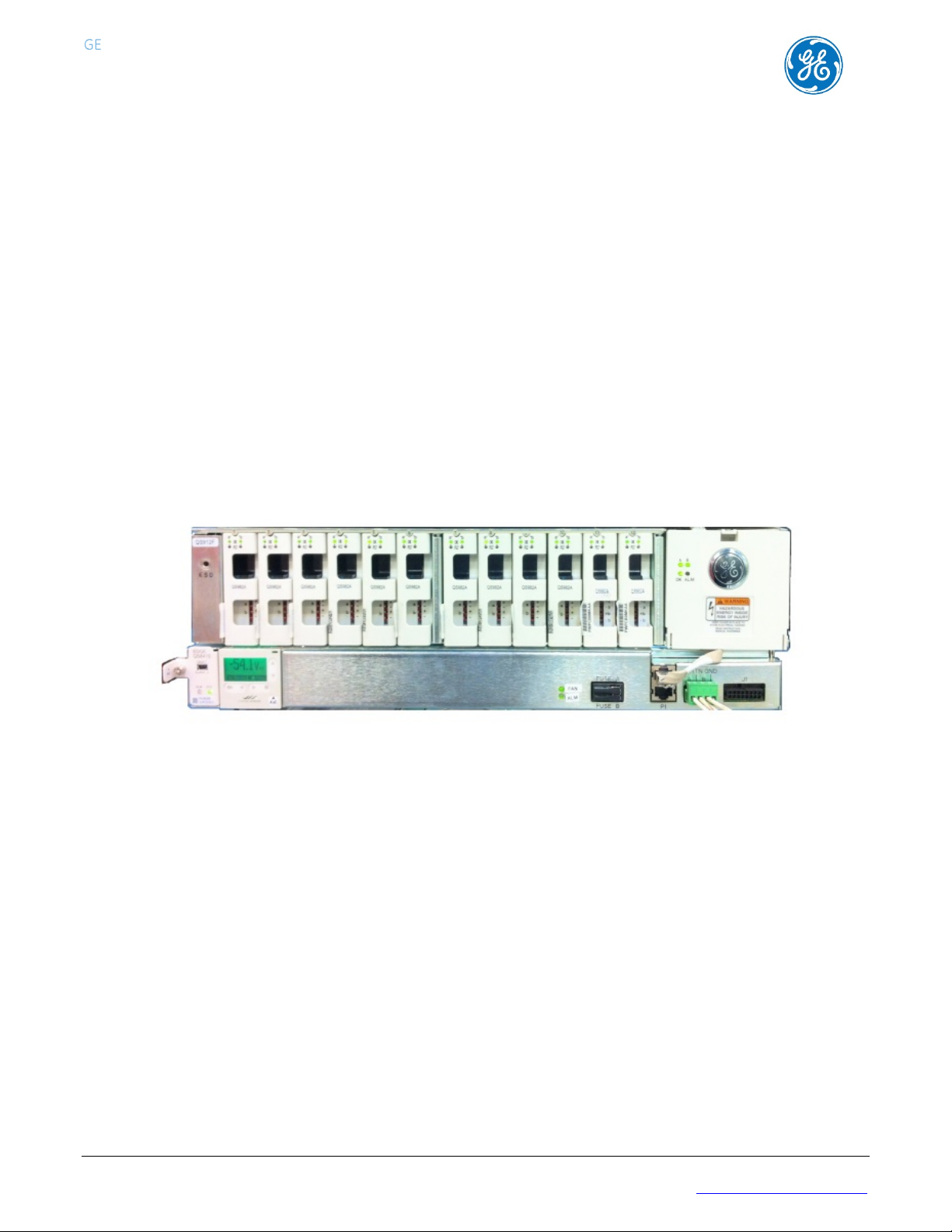
Product Description
The CPS2400U Upstream System delivers power over telephone lines. The primary application is enabling the delivery of
video bandwidth data rates to residences over twisted pairs by allowing placement of powered electronics at an
acceptable distance from the residence.
The Converter System distributes battery backed up power from existing -48V battery backed up sites such as Central
Offices and Remote Terminals to reliably power electronics near the home. It does this by converting the -48V to a
UL60950-21 safety approved + and – 190V current limited and ground fault protected sources.
Components and Features
See Line Power Product Line Brochure for details.
• Converter System
• Up to 24 converter shelves (576 output circuits)
• Converter Shelf - 19” shelf,
• Front access, mid-mount
• 12 Converter Card Slots, 24 output circuits
• Alarm Card
• Relays - Major and Minor, Form C
• Output Connector
• Redundant A and B -48V feeds
• Converter Cards
• Two independent dc/dc converters per card
• ±190 Vdc output, safety limited to 100VA and Ground Fault protected
• -48 Vdc input – Redundant A and B fed
• Connectorized and insulator shielded
• Hot swappable
• Fan Shelf
• Provides cooling air flow for a stack of up to 3 Converter Shelves
• Houses the system controller (optional)
• -48 Vdc input – Redundant A and B fed
• Redundant Cooling (optional with 2 Fan Shelves per stack of Converter Shelves
• Baffle
• Directs air flow - front intake, rear exhaust.
• Shields against material dropping into the Converter Shelves
• System Controller Galaxy Pulsar Edge – QS841E (optional)
• Web and SNMP over TCPIP
• Front Panel Display, Control, and Status LEDs
850028186 r04 December 2013 6
Page 7
CPS2400U Upstream System – 19” Product Manual CPS2400U
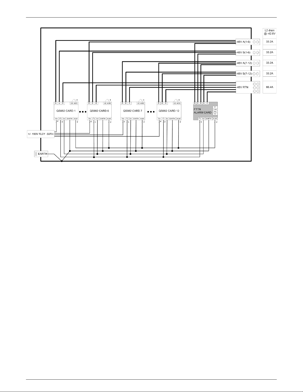
Figure 1 Block Diagram -48V Fed Converter Shelf
Operation
-48V power input is distributed in an A and B redundant fashion to each of the converter cards and the alarm card.
There are two +/-190V circuits on each converter card. The circuits both boost the voltage and limit the current as
prescribed by UL60950-21 and GR-1089-CORE.
Warning: Ground faults or short circuits on the output do not permanently disconnect the output. The converter
circuit tests the line every 4 seconds and will re-energize if the wiring fault is cleared.
A serial communication bus links each converter to an alarm card at the end of each shelf.
The alarm card provides major and minor form C contacts, manages the converters and relays information to an
optional system controller using Galaxy Protocol over an RS485 bus. Up to 24 shelves can be controlled and monitored
by one system controller. The controller is WEB and SNMP capable.
850028186 r04 December 2013 7
Page 8
CPS2400U Upstream System – 19” Product Manual CPS2400U
Baffle
Baffle
Converter Shelves
Fan Shelves - 1 or 2
Converter Shelf Stack
Converter Shelf Stack
Controller
Converter Shelves
Fan Shelves - 1 or 2
Baffle
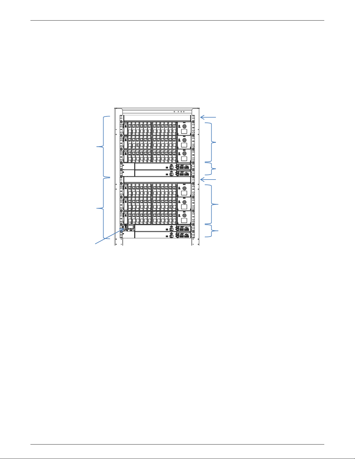
Configurations
Refer to Line Power System product line brochure for details.
Converter System 1 to 24 Converter Shelves (arranged in Converter Shelf Stacks)
+ 1 Controller (optional)
Optional Controller is installed in the Primary Fan Shelf.
Primary Fan Shelf not required in systems without Controller.
Converter Shelf Stack 1 to 3 Converter Shelves
+ 1 or 2 Fan Shelves
+ 1 Baffle
1 to 3
Secondary
no Controller
Primary
with Controller
in Primary Fan Shelf
1 to 3
Figure 2 Configuration
850028186 r04 December 2013 8
Page 9

CPS2400U Upstream System – 19” Product Manual CPS2400U
WARNING: Shock Hazard
•Complete Standard Insulated tool set
•Wire cutters and strippers
•Digital meter, +/- 0.02%
•Heat shrink gun
•Screw Drivers (flat-blade and Phillips)
•Torque wrench (0-240 in-lb / 28 Nm)
•ESD wrist strap
•Socket set
Installation
Prepare for Installation
Safety
Read and follow all safety statements, warnings, and precautions in the Safety section and Specifications section of
this manual and manuals of all other equipment before installing, maintaining or repairing the equipment.
WARNING: Shock Hazard
Load outputs are current limited +/-190V.
Outputs re-energize within 4 seconds when ground faults or short circuits are cleared.
Installation Tools
Equipment Identification
Identify the product you have received. Make sure to select procedural steps to match the equipment being installed.
Plan Installation
The system has been designed for mounting in relay racks or in equipment cabinets. It is designed for use with user
provided vertical airflow.
• Follow site specific engineering instructions to assure proper airflow for the specific installation.
• Refer to the Vertical Spacing, Airflow, Baffles, and Fan Shelves section for general spacing requirements.
Follow site engineering instructions.
Converter system shelves are installed arranged as one or more Converter Shelf Stacks.
Baffles
• Baffle Required at top of each Converter Shelf Stack in customer premise locations for UL compliance.
Baffles not Required in outside plant cabinets, CEVs, or huts.
• Baffles must be oriented to direct air in from the front (aisle) and out to the back of the rack.
Vertical Space Rules:
• Vertical space is permitted below Baffles for future Converter Shelf addition.
Baffle may be installed 12.5 inch rack space above a Fan Shelf.
• No vertical space between:
• Fan Shelves
• Fan Shelf and Converter Shelf
• Converter Shelves
Airflow and Fan Shelves
• Upward Airflow – provided by Fan Shelves.
• Fan Shelves provide adequate airflow for specified operating temperatures.
Airflow per specification may be provided by other devices.
• A Fan Shelf is required for each Converter Shelf Stack.
850028186 r04 December 2013 9
Page 10
CPS2400U Upstream System – 19” Product Manual CPS2400U
Step
Action
1.
Before opening the packaging, carefully inspect the outside in the presence of shipping personnel for
signs of damage.
2.
Carefully open the packaging to verify that the contents are complete and undamaged.
3.
If damaged, follow the shipping carrier’s procedure for filing a damage claim.
4.
Save the shipping packaging until all parts are operating within specifications.
If the equipment must be returned, it should be repacked in the original shipping packing.
Step
Action
Notes:
5. Baffle –Orient to direct air in from the front (aisle) and out to the back of the rack.
1.
Mount Lowest Fan Shelf in a position allowing space above for all planned shelves.
2.
Mount the remaining shelves and baffles above the lowest shelf, working from bottom to
top.
• 1 Fan Shelf provides Converter Shelf Stack cooling.
• 2 Fan Shelves provide Converter Shelf Stack cooling with redundancy,
• Primary Fan Shelf
• Provides Controller support and Controller Display.
• Required only when the system is equipped with a Controller
• Maximum 1 per system
Planning Steps
1. Determine arrangement of each Converter Shelf Stack - Figure 2.
2. Determine vertical rack space required, including planned space for future expansion.
3. Determine the position of the lowest Fan Shelf.
Unpack Equipment
Make sure the framework has the space and the airflow to provide an acceptable operating environment for the
equipment. Then unpack the equipment.
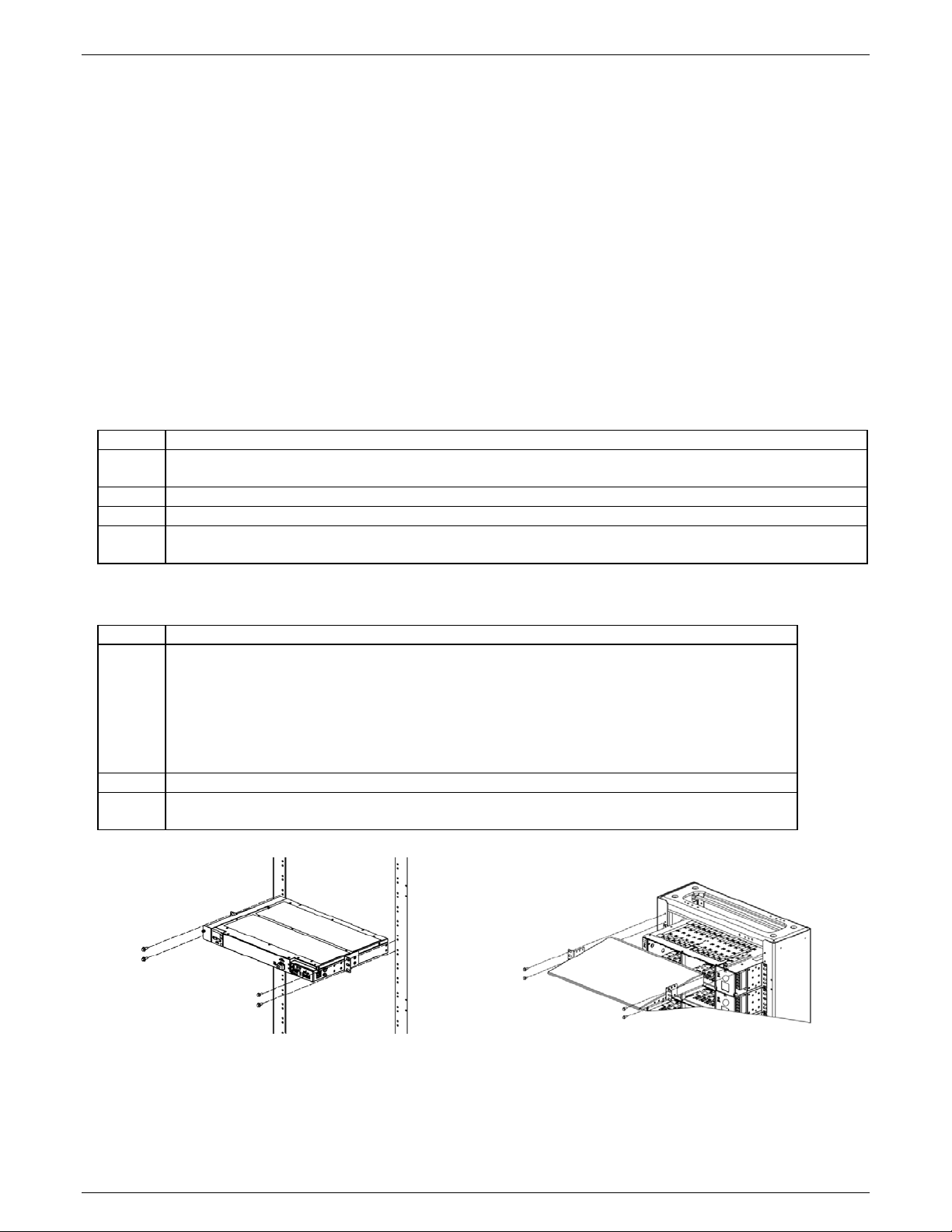
Mount Shelves
1. Secure shelves with as many screws as possible.
2. Torque each shelf mounting screws to 35 in-lb
3. Leave no vertical space between shelves
4. Follow site engineering instructions for shelf positioning and order.
See Plan Installation Section.
Figure 3 Fan Shelf Mounting
Figure 4 Baffle Mounting
850028186 r04 December 2013 10
Page 11
CPS2400U Upstream System – 19” Product Manual CPS2400U
Step
Action
1.
Run and connect the framework ground lead
2.
Repeat from for remaining Converter Shelves.
Ground Lead
Figure 5 Converter Shelf Mounting
Ground Converter Shelves
Fan shelves will be grounded when connecting input power.
to safety grounding point (frame ground, or main ground bar) per local practice.
6 AWG minimum
Apply NO-OX ID to all bare metal connections if required by local practice.
Torque to 35 in-lb (4 Nm).
Lugs landings - 1/4” studs on 5/8” centers.
Lugs for 6AWG conductor - T&B 6STR30W , Burndy YAV6C-L2TC14-FX or available equivalent:
Figure 6 Converter Shelf Ground
850028186 r04 December 2013 11
Page 12
CPS2400U Upstream System – 19” Product Manual CPS2400U
Step
Action
Converter Shelves Connect Power
1.
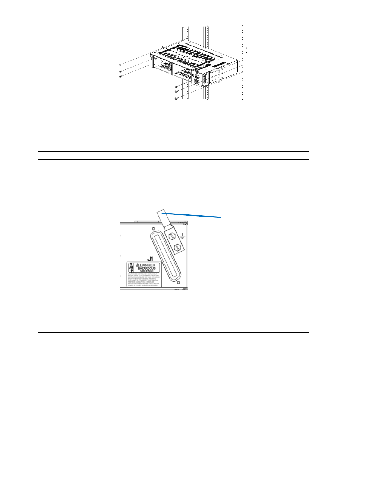
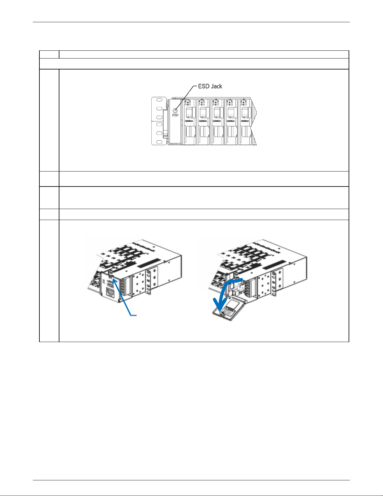
Connect your personal ESD strap to the ESD jack on the left of a converter shelf before proceeding.
2.
Verify voltage and polarity of each wire before connecting.
Use a Volt meter.
3.
Remove power from all DC connections to be installed.
Verify with a Volt meter.
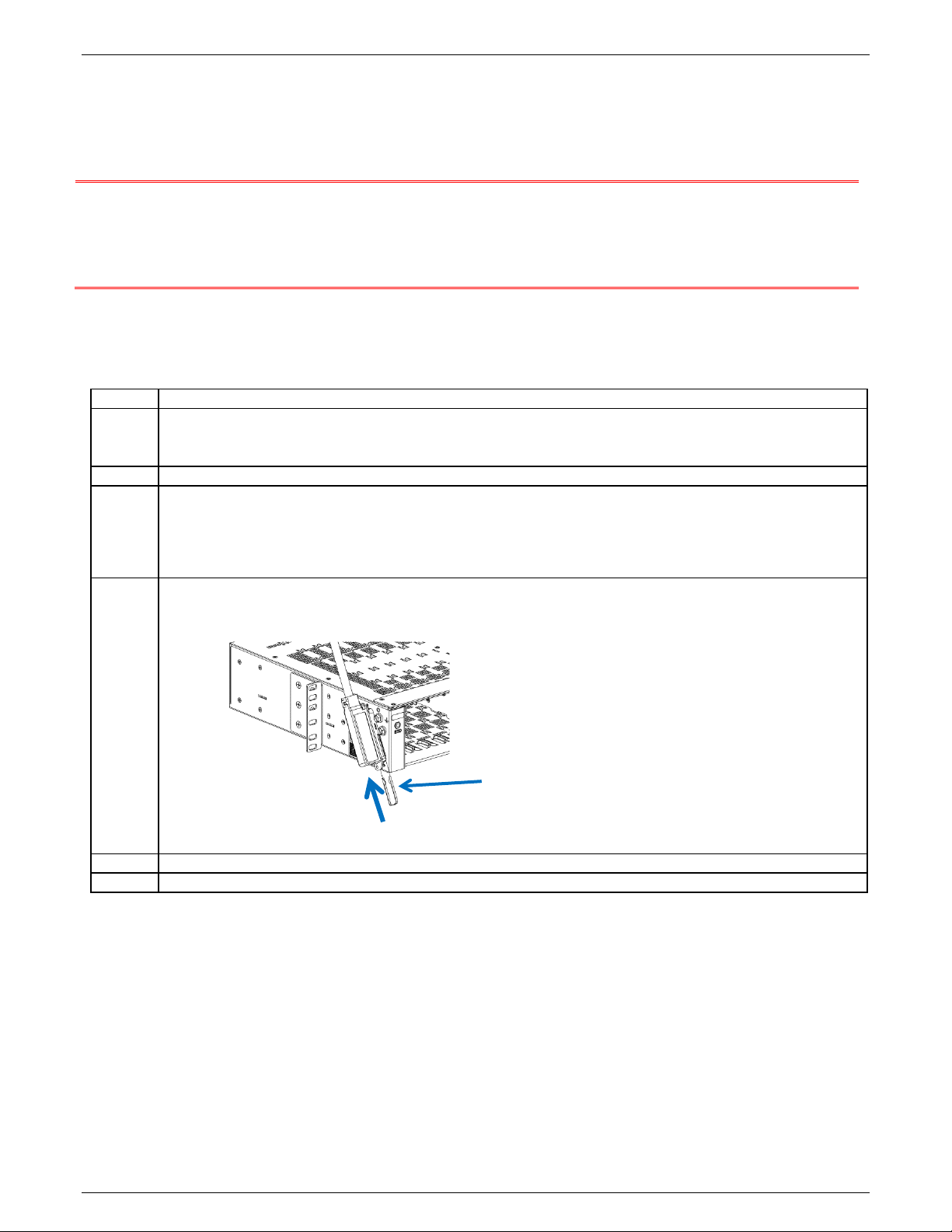
4.
5.
Open the distribution panel door on the right end of the shelf.
Press Latch to
Release Door
Connect Input Power
Figure 7 ESD Jack
Turn off circuit breakers and remove fuses.
Turn OFF circuit breakers assigned to this frame and verify with an volt meter
Figure 8 Converter Shelf DC Connections Access
850028186 r04 December 2013 12
Page 13
CPS2400U Upstream System – 19” Product Manual CPS2400U
Step
Action
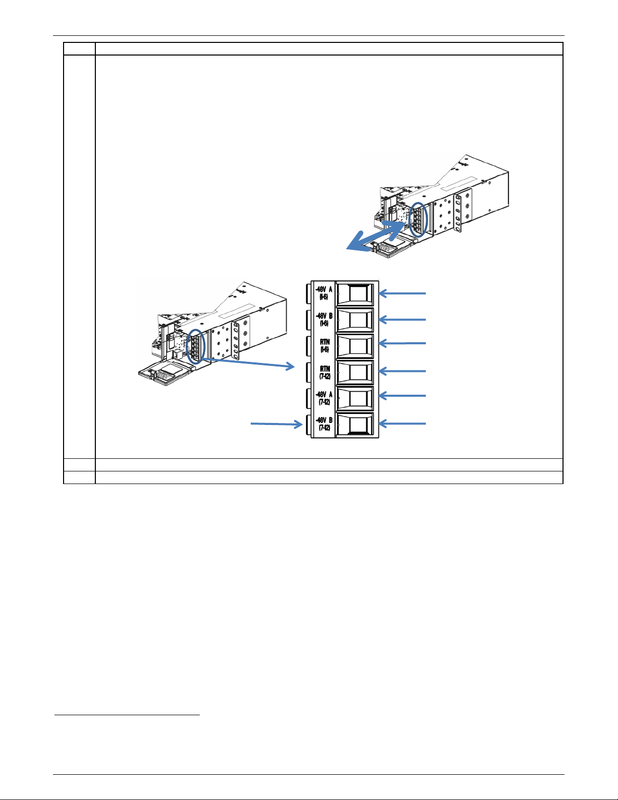
6.
Connect Four -48VDC branch circuits to the DC source
1. Pull connector straight off of its header.
7.
Close the distribution door.
Repeat from Step 2 for each Converter Shelves.
A -48V (1-6) Input
Screw
Notes:
1. Each feed supplies half of the shelf. A&B feeds for side 1 and A&B feeds for side 2.
2
2. Size each circuit to support 35 Amp List 2 Drains – 18-6AWG
.
3. Verify minimum loop cable length per Table 9.
4. -48V Returns (RTN) connections must be grounded.
2. Strip wire 1/2 inch
3. Insert wire fully into wire entry
4. Torque screw to 16 in-lb (1.7Nm)
5. Repeat from 2 for all wires
6. Push connector straight onto its header
B -48V (1-6) Input
RTN (1-6)
RTN (7-12)
A -48V (7-12) Input
B -48V (7-12) Input
Figure 9 Converter Shelf Input Power Connections
2
Reference NEC Table 310-16 for applications of not more than three conductors in a raceway and correction factors
for Ambient Temperatures over 30°C. Each installation will vary and the installer should review NEC cabling
requirements as well as local practice to ensure proper cable sizing is achieved for the local conditions.
850028186 r04 December 2013 13
Page 14
CPS2400U Upstream System – 19” Product Manual CPS2400U
Step
Action
Fan Shelves Connect Power
8.
Connect Input Power and Frame Ground
Repeat from Step 8 for remaining Fan Shelves.
A Feed (-48V)
Screws
24 - 16 gauge
Notes:
1. Each feed supplies half of the shelf. A&B feeds for side 1 and A&B feeds for side 2.
2. Power feeds should be derived from a fuse or breaker panel using discrete cabling which is
independent from the converter shelf.
3. Fuse externally at 10 Amps.
4. Use ring lugs or alternate per local practice.
5. Returns for the A and B feeds are shared on the -48Vdc RTN.
6. The right position on the terminal block is the frame ground for the Fan Shelf.
7. Connect de-energized DC cabling (typically 16 AWG) as shown here.
8. Connect Frame Ground wire.
-48V RTN
B Feed (-48V)
Frame Ground
Figure 10 Fan Shelf Input Power Connections
850028186 r04 December 2013 14
Page 15
CPS2400U Upstream System – 19” Product Manual CPS2400U
NOTE: Compliance Requirements
Step
Action
1.
Verify rating of all wire between the equipment and the primary protectors:
• 200V rated minimum
2.
Verify primary protection consistent with UL 497 is installed on all the telecommunication line cable.
3.
Mark or tag the load cable and load circuit panel.
Note: The panel may be a cross-connect panel or the 5-pin protector block near the building entrance.
4.
Run the load cable down the frame and attach as shown.
5.
Use Screw to secure.
Repeat for remaining Converter Shelves.
Clip
Connect Load Wiring
Provide a circuit from each converter into the designated network telephone pairs.
The wiring assignment information in Table 6 provides the appropriate connections for each circuit. Cables should be
provided with this pinout configuration to terminate the J1 output connector on each Converter Shelf.
• Connect only to UL60950-21 RFT-V Circuits.
• Do not connect to UL60950-21 RFT-C circuits.
• Output voltage (+/-190V) meets UL60950-21 RFT-V requirements.
• Use minimum 26AWG 200V rated wire between the converters and primary protectors.
Wireset Connector: RJ-21 type 50 pin plug:
• 22 AWG solid or stranded AMP 552173-1 or equivalent.
• 24 AWG solid or stranded or 26 AWG solid AMP 229974-1 or equivalent.
• The connector must be arranged with a right angle housing such that the cable exits to the pin 1 side.
• 26 AWG minimum
1. Mark the Converter Shelf load cable with the Shelf number.
2. Mark each load circuit at the panel converter number (including the shelf number).
1. Seat the cable connector to the shelf connector.
2. Secure the connector with the clip.
Figure 11 Converter Shelf Load Connector
850028186 r04 December 2013 15
Page 16

CPS2400U Upstream System – 19” Product Manual CPS2400U
Step
Action
1.
Is accessibility to the circuit throughout the network consistent with A2 requirements?
2.
Is the 5-pin protector marked as a special circuit?
3.
Does the 5-pin protector protect each pair to a level corresponding to a CommScope 3C*EW Gas tube
<265-700 Volts. Protectors with a lower voltage breakdown rating will be problematic.
Step
Action
1.
Recognize that the Remote Feed Telecommunication Voltage limited (RFT-V) circuit is voltage limited to
+190V and -190V from ground.
2.
Is the total capacitance to ground on each line of the circuit less than 10μF?
capacitance. .
3.
Is the total capacitance line to line of the circuit less than 40μF?
capacitance from tip to ring.
4.
Is the remote equipment also a RFT-V voltage limited circuit?
equipment is connected together.
5.
Is the voltage rating of the Network Wiring sufficient to support 190V to ground?
6.
Is the wire between the converters and primary protectors minimum 26AWG 200V rated?
7.
Is the chassis of the system bonded to ground?
Many network providers use a maximum value of 10 ohms.
Inspect the Network
Check and Mark Wiring Compliance
The system is classified as an A2 circuit tested according to GR-1089-CORE Issue 3. As such, each location in the
network where the output is available to be touched must be protected and marked as an A2 voltage.
primary protector?
This protector has a voltage breakdown range of 265-465 Volts and an impulse spark over range of
Verify UL Installation Compliance
• This verification is required at the time of installation to meet UL60950-21.
• Perform this verification before power is distributed in the network.
Normally the final step is performed by closing the circuit using a 5-pin protector after DC power is applied to the
system.
The QS982 introduces 4.4μF. The remote electronics and line must introduce less than 5.6 μF of
The QS982 introduces 2.2μF. The remote electronics and line must introduce less than 37.2 μF of
Both ends of the circuit must be designed to the same standard. This must be verified before the
Verify by both observation and measurement before powering the system. Measurement from the
exterior of the Converter Shelf to the cabinet ground bus should indicate continuity as determined via a
meter providing an audible beep or the standard method of continuity verification used in the network.
850028186 r04 December 2013 16
Page 17

CPS2400U Upstream System – 19” Product Manual CPS2400U
8.
Test each circuit by powering an open circuit at the remote end of the wire with a QS982 output. If red
power applied to the system.
Step
Action
1.
Remove the cover from the left hand end of the Primary Fan Shelf (with the display).
2.
Insert controller into slot on the left of the Fan Shelf.
Screw
lights do not flash, there is no leakage path to ground at operating voltage. If the FLT light does not blink
yellow, there is no hard short between tip and ring.
Note: 1. This step is shown here only for completeness.
It is to be performed after the Apply DC Power section is completed.
2. Circuit powering is usually accomplished by closing the circuit using a 5-pin protector after DC
Install Controller
Secure with captive screw.
Figure 12 Fan Shelf Controller Cover
Figure 13 Controller Installation
850028186 r04 December 2013 17
Page 18

CPS2400U Upstream System – 19” Product Manual CPS2400U
Step
Action
1.
Open the distribution door.
2.
Remove the alarm card.
Press Latch to
Bring door to level position
Door must be fully open to
remove alarm card
Set Shelf ID
Systems Equipped With Controller - Set ID (address) of each shelf to a unique value.
Systems Without Controller –ID (address) not used.
Release Door
before removing alarm card
Figure 14 Alarm Card Access
Figure 15 Alarm Card Removal
850028186 r04 December 2013 18
Page 19

CPS2400U Upstream System – 19” Product Manual CPS2400U
Step
Action
3.
Set the shelf address rotary switch to indicate a shelf ID (0, 0 if not equipped with a controller).
4.
Insert alarm card and close door.
Repeat for each remaining Alarm Card.
Use a small Phillips screw driver.
Start with shelf ID 1 at the bottom and progress up the frame to higher numbers.
Settings for shelf 1 and shelf 6 shown in Figure 16.
Note: “Cards per Shelf” is factory set to the unit digit of the number of card slots per shelf,
set to 2 for 12 cards per shelf.
Figure 16 Shelf ID Setting
850028186 r04 December 2013 19
Page 20

CPS2400U Upstream System – 19” Product Manual CPS2400U
Step
Action
1.
Install Inter-Shelf cables between all shelves in the system.
Step
Action
1.
Install Controller Office Alarm Cable4
Inter-Shelf Cables
different signals.
Inter-Shelf Cable to Bottom
Inter-Shelf Cable to Top
Converter Shelf doors not shown.
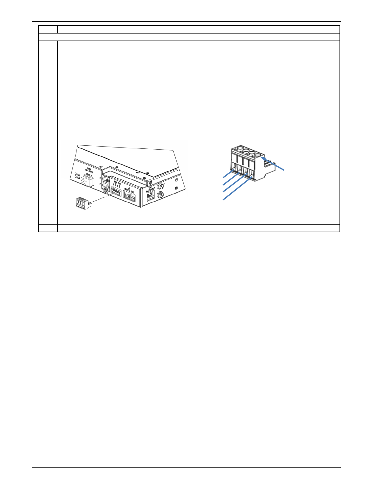
J1 Office Alarm Connector
Install Inter-Shelf Signal Cables
Each Converter Shelf Alarm Card communicates with the Fan Shelf and Controller via daisy chained cables.
Note: Install RJ-45 cables as shown.
Top (P1) and Bottom (P2) connectors have different signals.
3
Cable from the top RJ45
connector of each shelf to the bottom RJ453 connector of the shelf above.
Fan Shelf of Converter Shelf
Stack above, if present
Install only as shown.
Top (P1) and bottom (P2)
shelf connectors have
Connect Office Alarms
See Appendix C: Operation without a Controller - Alarm Wiring for systems without a controller.
1. Connect office alarm cable to J1 Office Alarm Connector on the Primary Fan Shelf (Fan Shelf with
Controller).
2. Dress cable out to alarm block and terminate alarms per site engineering instructions - Table 5.
Converter Shelf of Converter
Shelf Stack below, if present
Figure 17 Inter-Shelf Cables
3
RJ45 connectors of Converter Shelves are located on their Alarm Cards.
4
Office Alarm Cable is separately ordered. For available cables see Line Power Product Line Brochure.
850028186 r04 December 2013 20
Figure 18 Controller Office Alarm Connector
Page 21

CPS2400U Upstream System – 19” Product Manual CPS2400U
Step
Action
1.
Connect local network wiring to Fan Shelf connector P6 (RJ-45).
2.
Check the network connection IP address assigned to the controller.
When an IP address is listed connection to the server is confirmed.
P6 10/100 Base-T
Connect Local Network
Figure 19 Controller Network Wiring Connection
1. Press the square key, ■, on the upper right hand corner of the keypad to display the menu.
2. Press the down arrow key, ▼, 2 times to scroll down to the “Status” item on the menu.
3. Press the right arrow, ►, to advance to the “Status” menu.
4. Press the down arrow key, ▼, repeatedly to scroll down to the “Network Settings” item and select by
pressing the right arrow key.
5. Press the right arrow, ►, to advance to the “Network Settings” menu.
6. Press the right arrow, ►, to select Port 1. The P6 connector is Port 1.
7. Read and record the network address for Port 1.
850028186 r04 December 2013 21
Page 22

CPS2400U Upstream System – 19” Product Manual CPS2400U
Step
Action
1.
Connect your personal ESD strap to the ESD jack on the left of a converter shelf before
2.
Remove the Converter from its shipping container.
3.
Install the Converter into the Shelf.
4.
Repeat from Step 2 for remaining Converters.
5.
Install empty slot fillers into all unused slots of multi-shelf Converter Shelf Stacks.
Step
Action
1.
Apply DC power by turning on circuit breakers and inserting fuses feeding both Fan Shelves and the
Converter Shelves.
Install Converters
removing the Converters from their anti-static wrap:
Figure 20 ESD Jack
1. Align the plastic converter housing on the right with the card guides at the top and bottom of
the slot.
2. Slide the converter into the slot.
3. Push firmly seat the converter until the converter latch engages.
Figure 21 Converter Installation
Apply DC Power
Fault LEDs will flash red until communications is established between the system components. – see Verify Normal
States for details.
850028186 r04 December 2013 22
Page 23

CPS2400U Upstream System – 19” Product Manual CPS2400U
Step
Action
1.
System Self Check
2.
Follow the Troubleshooting section to resolve any alarm states
Step
Action
1.
Test each circuit by powering an open circuit at the remote end of the wire with a QS982 output. If red lights
applied to the system.
Verify Normal States
The Controller display and LEDs on Converters, shelf Alarm Cards, and Fan Shelves will illuminate when power is applied
to the system.
Check for normal operation
1. Green Controller Display backlight
2. Green LEDs on each Alarm Card, each Converter, and each Fan Shelf
Every LED labeled “A”, “B”, “OK”, “FAN”, “a”, and “b”
3. No Red LEDs or displays.
Verify UL Installation Compliance
Complete the final step to verify UL installation compliance.
Figure 22 Normal LEDs
do not flash, there is no leakage path to ground at operating voltage. If the FLT light does not blink yellow,
there is no hard short between tip and ring.
Note: Circuit powering is usually accomplished by closing the circuit using a 5-pin protector with DC power
Configure Controller
Refer to Galaxy Pulsar Edge Quick Start Guide.
Verify and edit controller parameters per site engineering instructions.
Basic Configuration:
Installation Tab:
Site ID, Site Description, System Date, System Time, and Shelf J-Code or Product Code
Network page (Settings tab, Communications group):
DHCP Client / Fixed IP Address
FTTN page (Settings tab, System group):
Alarm parameters
Complete Configuration:
Verify and edit any additional controller parameters per site engineering instructions.
850028186 r04 December 2013 23
Page 24

CPS2400U Upstream System – 19” Product Manual CPS2400U
Confirm Operation of Alarm Wiring
After the converters are recognized to be in a normal state, one should confirm the proper operation of the alarm
contact closures. If alarm wiring is correct:
1. The loss of A or B input power should result in the assertion of a Power Minor.
2. The loss of both A and B input power, which will result in a loss of service, should result in a Power Major and a
Power Minor.
3. If a controller is installed in the system then it will indicate an alarm state by red display backlight. Using the
buttons on the keypad specific alarms can be retrieved by pressing the Back Arrow,. When the system
returns to normal function the display will be green.
850028186 r04 December 2013 24
Page 25

CPS2400U Upstream System – 19” Product Manual CPS2400U
Table 1 System Troubleshooting
Controller
Alarm Card
Converter Card
Alarm
State
OK
State
Alarm
State
Normal
Green
Green
none
Various
Yellow
Green
Green
Latched Controller Alarm
Execute Controller commands “Clear Events” and
Web Pages – Maintenance tab.
Circuit Fail
Yellow
Min
Yellow
Min
Green
Flashing
Yellow
Short + to -
Make sure each converter has an independent
isolated send and return path.
Circuit Fail
Yellow
Min
Yellow
Min
Flashing
Red
Flashing
Red
Short to Ground
Make sure each converter has an independent
isolated send and return path.
Communication
Fail
Yellow
Min
Yellow
Min
Green
Off
1 Card Removed
Check to see that all cards are seated.
Replace non-functioning cards.
Communication
Fail
Red
Maj
2 Cards Removed
Check to see that all cards are seated.
Replace non-functioning cards.
Communication
Red
Maj
Flashing
Green
Off
Communication Cable
Check communication path from alarm cards to
communication.
Communication
Fail
Red
Maj
Green
Flashing
Red
Alarm Card Removed
Replace Alarm card.
None
Green
Green
Yellow
Standby
Remove unit from standby if desired using
Controller or web page interface
Circuit Fail
Yellow
Min
Yellow
Min
Green
Flashing
Open Fuse
Replace Converter.
service to the other line served by the Converter.
Troubleshooting
Only Remote Power System specific alarms are included in this section. See Galaxy Pulsar Edge Product Manual for details of other controller alarms.
Many alarms are best processed at the converter shelf alarm card and converter card level.
LAN port or Craft port access provides additional information – see Galaxy Pulsar Edge Product Manual for details
System
Alarm Display
Fail
Back-
light
or Red
Relay
State
LED
Red
Relay
State
LED
LED
Possible Problem Possible Solution
or Alarm for Removed
Equipment
Removed
“Uninstall Equipment”.
Controller – Control/Operations
Controller.
If controller is not present, set alarm card rotary
switch to Shelf ID 0,0 for contact closures only
850028186 r04 December 2013 25
Yellow
Note: Replacing a Converter storing will interrupt
Page 26

CPS2400U Upstream System – 19” Product Manual CPS2400U
Table 1 System Troubleshooting
Controller
Alarm Card
Converter Card
Alarm
State
OK
State
Alarm
State
Circuit Fail
Yellow
Min
Yellow
Min Flashing
Under Voltage
Replace Converter.
service to the other line served by the Converter.
Fan Fail
Yellow
Min
Yellow
Min
Green
Off
1 Fan Tray Failed
Replace fan shelf or tray.
Fan Fail
Yellow
Min
Yellow
Min
Green
Off
1 of 6 fans Failed on one
Fan Shelf or Tray
Replace fan shelf or tray.
Fan Fail
Red
Maj
Red
Maj
Green
Off
2 Fan Shelves or Trays
Failed
Replace fan shelves or trays.
Input Power
Yellow
Min
A Red
Min
Green
Off
A1-6 Power Fail
Restore DC input power to the A1-6 input terminal.
Input Power
Yellow
Min
B Red
Min
Green
Off
B1-6 Power Fail
Restore DC input power flowing to the B1-6 input
terminal
Input Power
Yellow
Min
A Red
Min
Green
Off
A7-12 Power Fail
Restore DC power to the A7-12 input terminal
Input Power
Yellow
Min
B Red
Min
Green
Off
B7-12 Power Fail
Restore DC power to the B7-12 input terminal.
Input Power
Mul Circuit Fail
Red
Maj
A Red
B Red
Maj
Green
Off
A1-6 & B1-6 Power Fail
Restore DC power to the A1-6 input terminal and
Restore DC power to the B1-6 input terminal
Input Power
Mul Circuit Fail
Red
Maj
A Red
B Red
Maj
Green
Off
A7-12 & B7-12 Power Fail
Restore DC power to the A7-12 input terminal.
Restore DC power to the B7-12 input terminal.
Load Drop
Yellow
Min
A, B &
Green
Green
Off
Load Drop
Check the integrity of the circuits going to the load.
feature.
Load Share
Yellow
Min
A, B &
Green
Off
As set of circuits
be expected.
Check the integrity of the circuits going to the load.
Line Test
A, B &
Green
Green
Off
OK, Fail or Aborted
Estimated line resistance has increased since last
Loss Of
Yellow
Min
A, B &
Green
Green
Off The loss of n additional circuits will cause
Check redundancy threshold in the configuration.
Alarm Display
Back-
light
Relay
State
LED
OK
OK
Green
Relay
State
LED
LED
Yellow
Possible Problem Possible Solution
Note: Replacing a Converter storing will interrupt
Or Adjust load drop threshold to 0 to disable this
assigned to one remote
destination are not
sharing current as would
Or Adjust load share threshold to disable this
feature.
Redundancy
850028186 r04 December 2013 26
OK
OK
measurement.
customers to lose service.
Page 27

CPS2400U Upstream System – 19” Product Manual CPS2400U
Table 2 -48V Input Feed Alarm State and LEDs
A / B LEDs
(Alarm Card)
-48V Input Feed Alarm
State
A
1-6
B
1-6
A
7-12
B
7-12
A B
Green
Green
OK
Low Red
Green
Minor
Low
Green
Red
Minor
Low Red
Green
Minor
Low
Green
Red
Minor
Low
Low
Red
Red
Major
Low Low Red
Green
Major
Low
Low
Red
Red
Major
Low
Low Red
Red
Major
Low Low
Green
Red
Major
Low
Low
Red
Red
Major
Low
Low
Low Red
Red
Major
Low
Low Low
Red
Red
Major
Low Low
Low
Red
Red
Major
Low
Low
Low
Red
Red
Major
Low
Low
Low
Low
Unpowered
Input Feed LEDs
Alarm State LEDs
Alarm Card
The Alarm Card aggregates alarms from shelf Converter Cards, shelf -48V dc input feeds, and Fan Shelves connected to
its P2 connector. Alarm Card LEDs and Relays present the aggregated Alarm Card State - Table 3.
A and B
OK and ALM
Figure 23 Alarm Card LEDs
Alarm Card LEDs and Relays
• A and B LEDs indicate the alarm state of each of the -48V Input Feeds to the shelf
(see Table 2).
• OK and ALM LEDs and Relays indicate the combined alarm state of the shelf, including Converter Cards and -
48V input voltage feeds.
-48 V Input Feeds5
5
Empty cells indicate: OK for inputs, OFF for LEDs, and non-alarm for relays.
850028186 r04 December 2013 27
Page 28

CPS2400U Upstream System – 19” Product Manual CPS2400U
Table 3 Alarm Card State LEDs and Relays
Alarm States
LEDs6
Relays
7, 6
Converter
State
-48 V Feed
State
Fan Shelf
State
OK LED
ALM LED
PMN
PMJ
OK
OK
OK
Green
Minor
OK or Minor
OK or Minor
Amber
PMN
OK or Minor
Minor
OK or Minor
Amber
PMN
OK or Minor
OK or Minor
Minor
Amber
PMN
Major
any
any Red PMJ
any
Major
any Red PMJ
any
any
Major
Red PMJ
any
Unpowered8
any
PMN
PMJ
Alarm Card Alarm States
Alarm states are ranked from low severity to high severity.
Alarm State Severity
Major or PMJ ....................... Highest
Minor or PMN ...................... Medium
None or OK .............. Lowest (no alarm)
Alarm states are aggregated and combined into successively larger representations:
Converter circuit states are aggregated into a Converter Card state.
Converter Card states and -48V Input Feed states are aggregated and combined into a Converter Shelf state.
Converter Shelf states and Fan Shelf states are aggregated and combined into a Converter system state.
• System Alarm State - the highest alarm state within the system, including Converter Shelves and Fan Shelves.
• Shelf Alarm State - the highest alarm state within the shelf, including Converter Cards and -48V Input Feeds,
Fan Shelf state (if wired), and Alarm Card I
2
C to RS-485 communication processor.
OK No alarms are active – all OK
PMN Minor alarms only are active
PMJ Major – at least one major alarm is active
• Fan Shelf Alarm State – the alarm state of the connected Fan Shelves.
Each Fan Shelf has a single alarm that is active when one or more fans have failed or when Fan Shelf DC
voltage is low.
OK No Fan Shelves have alarms are active – all OK
Minor One Fan Shelf has alarm active
Major Two Fans Shelves have alarms active
• Converter Card Alarm State - the highest alarm state of all Converter Cards within the shelf
OK No Converter alarms are active – all OK
Minor at least one Minor Converter alarms only is active
Major at least one Major Converter alarm is active
• -48V Input Feed Alarm State – the alarm state of the four -48V shelf feeds: - Table 2.
OK None
Minor One input feed Low
Major Multiple input feeds Low
6
Empty cells indicate: OK for inputs, OFF for LEDs, and non-alarm for relays.
7
Alarm relays are energized (powered) in the non-alarm state.
8
The Alarm card is redundantly powered by all four -48V input feeds.
850028186 r04 December 2013 28
Page 29

CPS2400U Upstream System – 19” Product Manual CPS2400U
Table 4 Converter LEDs
Action Required
OK LED
Fault LED
Conditions
Notes
None
Green
Off
All OK
Verify circuit
Off
Yellow
Standby
Standby can be set using the Controller
browser.
Check seating on
converter card
Green
Blink Red On ½ second,
Loss of comm.
Check 5 pin
to ground
Red Blink
Red Blink
Ground fault
Check output lines
other
Green
Yellow Blink
Overcurrent or under
Replace unit
Red Blink
Off
OV or internal failure
Solve Thermal
problem
Off
Red Blink
Thermal Alarm
Latch off after 3 retry cycles
Check source
Off
Off
card not powered or
input fuse failure
Observe Lamp Test
Bi-Color: 4.5 seconds
1 second off
Bi-Color: 4.5 seconds
1 second off
Lamps test requested
Display Examples
LED Display9
Conditions
Action Required
All OK
None
Circuit Placed in Standby
None depending on desired state of the circuit
Converter LEDs
configuration
Alarm card and
protectors and faults
for shorts to each
voltage
Figure 24 Converter LEDs and Test Points
Note: Test points work best if each voltage is measured with respect to ground.
display or remotely using a web
Off ¼ second
voltage
on, 4.5 seconds on and
on, 4.5 seconds on and
from controller
9
Examples in the table are shown for conditions on the B circuit of the QS982A card. The same Conditions and Actions
apply for the A circuit when A circuit LEDs are illuminated.
850028186 r04 December 2013 29
Standby state can be set using the controller or
web browser.
Page 30

CPS2400U Upstream System – 19” Product Manual CPS2400U
Table 4 Converter LEDs
Action Required
OK LED
Fault LED
Conditions
Notes
Loss of communication with
Check seating on Alarm card and converter card
Ground fault
Check 5 pin protectors and faults to ground
Overcurrent
Check output lines for shorts to each other
Overvoltage
Replace Converter Card
Thermal Alarm
Solve thermal problem
Card not powered or input
Check source voltage
Lamp test requested from
Observe Lamp Test
controller
or
Under voltage
or
Internal failure
Latch alarm after 3 retry
cycles.
fuse failure
controller
Locating Failed Fans
This information is for reference only. Fan replacement is by Fan Shelf replacement.
The fail LED on the Fan Shelf indicates the position of the failed fan by the number of LED flashes.
850028186 r04 December 2013 30
Figure 25 Fan Locations
Page 31

CPS2400U Upstream System – 19” Product Manual CPS2400U
Table 5 Controller Office Alarm Cable
Factory Default
Software Default
1
BLK
Input Alarm 5 (Closure to pin 3)
2
W
Input Alarm 3 (Closure to pin 3)
3
R/BLK
System –48V for Input Alarms ABS
4
OR
Alarm Relay 5 Return
PMJ Return
5
OR/BLK
Alarm Relay 6 Return
PMN Return
6
R/WHT
Alarm Relay 1 Return
7
WHT/BLK
Alarm Relay 2 Return
8
BL/R
Alarm Relay 3 & 4 Return
9
R
Input Alarm 8 (Closure to pin 3)
10
GR
Input Alarm 4 (Closure to pin 3)
11
BL
Alarm Relay 4
Open on Alarm
12
GR/BK
Alarm Relay 5
Open on Alarm
PMJ
13
BL/BK
Alarm Relay 6
Open on Alarm
PMN
14
GR/WHT
Alarm Relay 1
Open on Alarm
15
WHT/R
Alarm Relay 2
Open on Alarm
16
OR/R
Alarm Relay 3
Open on Alarm
Reference Information
This section contains additional information (connector pin designations, etc.) that may be required for making,
customizing, or troubleshooting system connections.
Connections
Controller Office Alarm Connections
See Appendix C: Operation without a Controller - Alarm Wiring for systems without a controller.
Controller Office Alarm Connector is located on the front of the Primary Fan Shelf - Figure 28.
Figure 26 Office Alarm Connections with Controller
Pin Color Signal
850028186 r04 December 2013 31
Page 32

CPS2400U Upstream System – 19” Product Manual CPS2400U
Table 6 Converter Shelf Output Connector Pinout
Converter Out
Pin
Color
Converter Out
Pin
Color
1a- 1 BL / W
1a+
26
W / BL
1b- 2 O / W
1b+
27
W / O
2a- 3 G / W
2a+
28
W / G
2b- 4 BR / W
2b+
29
W / BR
3a- 5 SL / W
3a+
30
W / SL
3b- 6 BL / R
3b+
31
R / BL
4a- 7 O / R
4a+
32
R / O
4b- 8 G / R
4b+
33
R / G
5a- 9 BR / R
5a+
34
R / BR
5b-
10
SL / R
5b+
35
R / SL
6a-
11
BL / BK
6a+
36
BK / BL
6b-
12
O / BK
6b+
37
BK / O
7a-
13
G / BK
7a+
38
BK / G
7b-
14
BR / BK
7b+
39
BK / BR
8a-
15
SL / BK
8a+
40
BK / SL
8b-
16
BL / Y
8b+
41
Y / BL
9a-
17
O / Y
9a+
42
Y / O
9b-
18
G / Y
9b+
43
Y / G
10a-
19
BR / Y
10a+
44
Y / BR
10b-
20
SL / Y
10b+
45
Y / SL
11a-
21
BL / V
11a+
46
V / BL
11b-
22
O / V
11b+
47
V / O
12a-
23
G / V
12a+
48
V / G
12b-
24
BR / V
12b+
49
V / BR
*FR GRD
25
SL / V
*FR GRD
50
V / SL
Ground Lead
Converter Outputs
Figure 27 Converter Shelf Output Connector
Wireset Connector: RJ-21 type 50 pin plug:
• 22 AWG solid or stranded AMP 552173-1 or equivalent.
• 24 AWG solid or stranded or 26 AWG solid AMP 229974-1 or equivalent.
• The connector shall be arranged with a right angle housing such that the cable exits to the pin 1 side.
*EMI performance is enhanced when the output cable shield is grounded only at the CPS2400
end of the shield.
850028186 r04 December 2013 32
Page 33

CPS2400U Upstream System – 19” Product Manual CPS2400U
A Feed (-48V)
Office Alarm Connector
P6 10/110 Base-T
Power Input Connector
Fan Shelf
See the Controller Office Alarm Connections section for Office Alarm detail.
-48V RTN
B Feed (-48V)
Frame Ground
Figure 28 Fan Shelf Connections
Note: Returns for A and B feeds are shared on the -48V RTN terminal.
Vertical Spacing, Airflow, Baffles, and Fan Shelves
Overview
The Converter System has been designed for mounting in relay racks or in equipment cabinets.
• It is designed for use with user provided vertical airflow cooling of at least 175 linear feet per minute over the
entire flow cross-section of the shelf.
• Equipment may be placed on top of the CPS2400U provided airflow is not impeded or sufficient spacing is
provided.
Outdoor Cabinet Application
The Converter System is rated to work to 65°C in stacks of two shelves in outdoor cabinets without baffles.
Note: where the air entering the second shelf may be heated above 65C inlet temperature, additional airflow beyond
the minimum 175 linear feet per minute is required. These cases require an engineered solution.
Central Office Application
Converter Shelf Stacks (Figure 2) are rated to operate in 55°C environments.
• Up to 2 Converter Shelf Stacks may be mounted in a single frame.
• No vertical space between:
• Fan Shelves
• Fan Shelf and Converter Shelf
• Converter Shelves
• A 3 inch minimum horizontal space is required to the rear of the baffle.
Specific testing is required If the space available is less than 3 inches.
• Slot covers must be installed used on all empty Converter slots when more than one Converter shelf is being
cooled by a Fan Shelf. These covers prevent cooling air from bypassing the Converters. See Figure 29.
850028186 r04 December 2013 33
Figure 29 Converter Slot Covers
Page 34

CPS2400U Upstream System – 19” Product Manual CPS2400U
Table 7 Lugs
GA
Description
WP-91412
List
Part #
Burndy Equivalent
Panduit Similar10
T&B Similar10
2
Straight, STR
54
405348202
YA2CL-2TC14
LCD2-14A-Q
54207 (STR)
2
Straight, FLEX
8
405347683
YAV2C-L2TC14-FX
LCDX2-14A-E
54208 (Flex)
2
45°, STR
-
-
YA2CL-2TC14-45
LCD2-14AH-Q
54207UF (STR)
2
45°, FLEX
193
408210524
YAV2C-L2TC14-FX-45
LCDX2-14AH-E
54208UF (Flex)
4
Straight, STR / FLEX
5
405347576
YAV4C-L2TC14-FX
LCDX4-14A-L (FLEX)
LCD4-14A-L (STR)
54206 (STR)
54206 (FLEX)
4
45°, STR / FLEX
-
-
YAV4C-L2TC14-FX-45
LCDX4-14AH-L (FLEX)
LCD4-14AH-L (STR)
54206UF (STR)
54206UF (FLEX)
6
Straight, STR / FLEX
3
405347519
YAV6C-L2TC14-FX
LCDX6-14A-L (FLEX)
LCD6-14A-L (STR)
54205 (STR)
54205 (FLEX)
6
45°, STR / FLEX
-
-
YAV6C-L2TC14-FX-45
LCDX6-14AH-L (FLEX)
LCD6-14AH-L (STR)
54205UF (STR)
54205UF (FLEX)
8
Straight, STR / FLEX
75
406021626
YA8CL2TC14
LCDX8-14A-L (FLEX)
LCD8-14A-L (STR)
542040410 (STR)
542040410 (FLEX)
8
45°, STR / FLEX
-
-
YA8CL2TC14-45
LCDX8-14AH-L (FLEX)
LCD8-14AH-L (STR)
N/A
Lugs
Lugs are not provided with the equipment. This information is provided as a convenience.
10
These similar lugs may have different dimensions from WP-91412 lugs.
850028186 r04 December 2013 34
Page 35

CPS2400U Upstream System – 19” Product Manual CPS2400U
Table 8 Specifications
Electrical and Thermal
Parameter
Symbol
Min
Typical
Max
Unit
Input Voltage
Operating Continuous
Non-operating, No Damage
V
-40 0 -52.8
-60
-40
Vdc
Transient (@ duration =)
5 seconds
V
tr
-65
V
10 ms (rise and fall rate of 10V/ms
V
tr
-75
10 µs
V
tr
-100
1 µs
Vt -200
Input Current per half shelf11
at 97.7W on all circuits
VIN = 54.4V
I
IN
26.0
Adc
VIN = 52.1V
I
IN
27.2
Adc
VIN = 42.6V
I
IN
33.2
Adc
VIN = 40.0V
I
IN
35.4
Adc
-48V Input Short Circuit Current Limit12
10,000
A
Power per Converter Card
at -42.6 Vdc input
Input Power
Pin
24013
W
Power Dissipation
Pdiss 21
4013
W
Output Power
Pout
200
W
Output
Output Voltage (line to line)
VO
378
380
382
Vdc
Output Power (per circuit)
PO
95.0
97.7
100
W
Output Current
IOUT
251
257
262
mA
Isolation Input to Output
1500
Vdc
Temperature Ambient
Operating at airflow14
at 150 lfm airflow
TA -40 50
°C
at 175 lfm airflow
TA -40 65
°C
at higher (TBD) airflow
TA -40 75
°C
Cold Start Temperature
TA
-40
°C
Storage Temperature
T
stg
-55 85
°C
Grounding / Bonding Network: Connect to an Isolated Ground Plane (Isolated Bonding Network) or an Integrated
Ground Plane (Mesh-Bonding Network or Common Bonding Network).
Equipment and subassembly ports: 1. are suitable for connection to intra-building or unexposed wiring or cabling;
2. can be connected to shielded intra-building cabling grounded at both ends.
Physical
Parameter
Symbol
Min
Typical
Max
Unit
Horizontal Clearance behind Shelves and Baffles
3
Inch
Component
Height
Width
Depth
Weight
Converter Shelf
3.3 in (84mm)
17.2 in (437mm)
11.9 in (303mm)
30 lb (13.6kg)
Fan Shelf
1.73 in (44mm)
17.2 in (437mm)
11.9 in (303mm)
20 lb (9.0kg)
1U Baffle
1.73 in (44mm)
17.2 in (437mm)
11.9 in (303mm)
5 lb (2.2kg)
Specifications
I
11
Each shelf has 4 feeds: redundant A and B feeds for each side of the shelf (half shelf). Each feed must be sized to fully
power the half shelf in the event of failure of the other redundant feed.
12
-48V feeds must be wired to limit short circuit current - Table 9.
13
These are maximum situations with each circuit loaded to 100W. No actual or engineered application would load
every circuit to this level. In the absence of detailed information about the network we would recommend using the
typical dissipation value of 21 W per card for most applications and 30W per card for highly loaded networks.
14
Airflow across the entire cross section of the warmest converter shelf.
850028186 r04 December 2013 35
Page 36

CPS2400U Upstream System – 19” Product Manual CPS2400U
Table 9 Minimum feed Loop Length 15 for 10,000 A Short Circuit Current
AWG
Minimum Loop Length
10
5 ft
8
8 ft
6
12 ft
4
19 ft
2
30 ft
Dimensions
Figure 30 Converter Shelf Dimensions
Figure 31 Fan Shelf Dimensions
15
Loop Length is the total length of -48V and -48V Return conductors.
850028186 r04 December 2013 36
Page 37

CPS2400U Upstream System – 19” Product Manual CPS2400U
Standards Compliance
• The equipment meets the applicable requirements of these North American product standards: UL60950-21,
UL60950-1, Telcordia GR-3108-CORE, GR-1089-CORE, GR-487-CORE (converter shelf), and GR-063-CORE.
• Baffle Required at top of each Converter Shelf Stack in CO and customer premise locations for UL compliance
(Baffles not Required in outside plant cabinets, CEVs, or huts).
• For multi-shelf systems (up to 3), this equipment has been evaluated for continuous use in ambient
temperature from -40°C to 65°C
• The main output voltage (+/-190V) meets UL60950-21RFT-V requirements.
DO NOT CONNECT TO RFT-C CIRCUITS.
16
.
Installation Area
Install only in restricted access areas (dedicated equipment rooms, equipment closets, or the like) in accordance with
articles 110-16, 110-17, and 110-18 of the U.S. National Electric Code (NEC), ANSI/NFPA No. 70, and pursuant to
applicable local codes.
Installation Environment
This equipment is to be used in controlled environments (an area where the humidity is maintained at levels that cannot
cause condensation on the equipment, the contaminating dust is controlled, and the steady-state ambient temperature
is within the range specified).
Installation Category
• Output circuits are suitable for connection to telephone lines that are equipped with primary lightning
protectors consistent with UL 497.
• Each copper pair must be provided with protection external to this equipment to a level equivalent to a
CommScope 3C*EW Gas tube primary protector [For example: 3C3EW provides the part in a red color]. This
protector has a voltage breakdown range of 265-465 Volts and an impulse spark over range of <265-700 Volts.
Protectors are provided by the telco customer.
• The 5-Pin protector must be marked as a “special circuit” consistent with the marking protocol in the users
network.
• Network equipment and components along the powering circuit shall have suitable insulation resistance at
200 Vdc from each conductor to ground and a total insulation resistance suitable for 400 Vdc from line to line.
16
-40°C to 55°C for 3 converter shelves and 2 Fan Trays when equipped with QS982A Converters.
850028186 r04 December 2013 37
Page 38

CPS2400U Upstream System – 19” Product Manual CPS2400U
Safety
Safety Statements
Read and follow all safety statements, precautions and warnings before installing, maintaining, or repairing the
equipment.
See the Specifications section for installation and environmental limitations.
• Grounding
• Connect the equipment chassis directly to ground. In enclosed equipment cabinets connect to the cabinet ac
service ground bus. In huts, vaults, and central offices connect to the system bonding network.
• Ground per National Electrical ode, local building codes, and customer standards, preacices, and requirements.
• Load outputs are hazardous
• current limited +/-190V
• Automatically re-energize within 4 seconds when ground faults or short circuits are cleared.
• Do not install this equipment over combustible surfaces.
• Follow all national and local rules and regulations when making field connections.
• Compression Connectors
• U. S. or Canada installations - use Listed/Certified compression connectors to terminate Listed/Certified field-
wire conductors where required.
• All installations - apply the appropriate connector to the correct size conductor as specified by the connector
manufacturer, using only the connector manufacturer’s recommended or approved tooling for that connector.
• Torque electrical connections to the values specified on labels or in the product documentation.
• Dress cables to avoid damage to the conductors and undue stress on the connectors.
• Size protectors (fuses or circuit breakers) as required by the National Electric Code (NEC) and/or local codes. Refer
to the equipment ratings to assure current does not exceed:
Continuous Load (List 1) - 64% of protector rating
Maximum Load (List 2 - typically end of discharge) - 80% of protector rating.
• Field-wired Conductors - Follow all National Electric Code (NEC) and local rules and regulations when making field
connections.
• Size field-wired conductors based on listed recommendations, National Electric Code (NEC) and/or local codes
based on 70°C ampacity.
• Insulation rating: 90°C minimum; 105°C (minimum) if internal to enclosed equipment cabinets.
• Provide accessible AC and DC input disconnect/protection devices to remove input power in an emergency.
• Provide external current limiting protection for alarm contacts. Rating 60V, 0.5A unless otherwise noted.
• Use only specified fuses and circuit breakers.
• Use only GMT fuses provided with safety caps.
850028186 r04 December 2013 38
Page 39

CPS2400U Upstream System – 19” Product Manual CPS2400U
Design Capacitance Safety Limit
The designed capacitance between +/-190V RFT-V conductors is 2.2uF and the measured capacitance between +/190V and earth is 4.4uF.
DO NOT add capacitance to the system to reach values that exceed safety limits per the following figure:
Figure 32 Design Capacitance Safety Limit
850028186 r04 December 2013 39
Page 40

CPS2400U Upstream System – 19” Product Manual CPS2400U
Precautions
• Install, service, and operate equipment only by professional, skilled and qualified personnel who have the necessary knowledge
and practical experience with electrical equipment and who understand the hazards that can arise when working on this type
of equipment.
• Disconnect batteries from outputs and/or follow safety procedures while working on equipment. Batteries may be connected in
parallel with the output of the rectifiers. Turning off the rectifiers will not necessarily remove power from the bus.
• Do not disconnect permanent bonding connections unless all power inputs are disconnected.
• Verify that equipment is properly safety earth grounded before connecting power. High leakage currents may be possible.
• Exercise care and follow all safety warnings and practices when servicing this equipment. Hazardous energy and voltages
are present in the unit and on the interface cables that can shock or cause serious injury. When equipped with ringer
modules, hazardous voltages will be present on the ringer output connectors.
• Use the following precautions in addition to proper job training and safety procedures:
• Use only properly insulated tools.
• Remove all metallic objects (key chains, glasses, rings, watches, or other jewelry).
• Follow Lock Out Tag Out (LOTO) procedures: customer specified, site specific, or general as appropriate.
Disconnect all power input before servicing the equipment. Check for multiple power inputs.
• Wear safety glasses.
• Follow Personal Protective Equipment requirements: customer specified, site specific, or general as appropriate.
• Test circuits before touching.
• Be aware of potential hazards before servicing equipment.
• Identify exposed hazardous electrical potentials on connectors, wiring, etc.
• Avoid contacting circuits when removing or replacing covers.
• Use a personal ESD strap when accessing or removing electronic components.
• Follow procedures for working at heights more than 4ft above the floor: customer specified, site specific, or general as
appropriate.
• Personnel with electronic medical devices need to be aware that proximity to DC power and distribution systems, including
batteries and cables, typically found in telecommunications utility rooms, can affect medical electronic devices, such as
pacemakers. Effects decrease with distance.
850028186 r04 December 2013 40
Page 41

CPS2400U Upstream System – 19” Product Manual CPS2400U
Appendix A: Operating Temperature
Measurement and Vertical Spacing
Overview
The CPS2400U has been designed for mounting in relay racks or in equipment cabinets. It is designed for use with user
provided vertical airflow cooling of at least 175 linear feet per minute over the entire flow cross-section of the shelf.
Equipment may be placed on top of the CPS2400U provided airflow is not impeded or sufficient spacing is provided. A
1U Baffle is required above the highest converter shelf; this baffle provides sufficient vertical spacing. Direct the airflow
into a 3 inch minimum space. If the spacing is less than 3 inch spacing application specific testing is required.
Operating Temperature
The CPS2400U is rated to work to 65 C in stacks of two shelves in outdoor cabinets without baffles. Note: in outdoor
cabinets where the air entering the second shelf may be heated above 65°C inlet temperature, additional airflow
beyond the 175 linear feet per minute is required. These cases require an engineered solution.
In Central Office environments when baffles are required for safety reasons, a three shelf system is rated to operate in
55°C environments.
Baffles and Fan Trays
For Central Office applications, baffles are used between every set of three Converter shelves. Fan Shelves are required
for every set of three Converter shelves. No more than 6 shelves may be located in a particular frame. Slot covers must
be used on all empty slots when more than one shelf is being cooled by a particular airflow device.
Always mount converter shelves above the fan tray that cools them.
Leave no space between the top of a fan tray and the converter shelf above it. The Fan Shelf draws air down through
whatever equipment is located directly above it. If a gap is left above a fan tray, air will be drawn into the fan tray from
the aisles rather than from the converter shelf above the fan tray. This will result in service effecting problems due to
insufficient cooling air flowing through the active converters.
The Fan Shelf forces air up through whatever equipment is located directly above it. If a gap is left above a fan tray, air
will escape into the aisles rather than flowing into the converter shelf above the fan tray. This will result in service
effecting problems due to insufficient cooling air flowing through the active converters.
Always mount a converter shelf immediately above a fan shelf or above a converter shelf stacked on a fan shelf. Any
gaps between converter shelves, or absence of slot covers, can cause service effecting problems.
Note: All unpopulated converter slots must be filled with slot fillers. For example the figure below shows a shelf with
operational converters in the first two slots and slot fillers in the remaining 10 slots:
Figure 33 Converter Slot Fillers
850028186 r04 December 2013 41
Page 42

CPS2400U Upstream System – 19” Product Manual CPS2400U
Table 10 Alarm Reference Table
Controller
Alarm Card
Converter Card
Alarm Display
What it means
LED
Relay
Alarm
State
Relay
OK
State
Alarm
State
Corrective Action
Circuit Fail
Short + to -
Yellow
Min
Yellow
Min
Green
Flashing
Make sure each
send and return path.
Circuit Fail
Short to Ground
Yellow
Min
Yellow
Min
Flashing
Flashing
Make sure each
send and return path.
Communication
1 Card Removed
Yellow
Min
Yellow
Min
Green
Off
Check to see that all
functioning cards.
Communication
2 Cards
Red
Maj
Check to see that all
functioning cards.
Communication
Communication
Red
Maj
Flashing
Green
Off
Check communication
communication.
Communication
Fail
Alarm Card
Removed
Red
Maj
Green
Flashing
Red
Replace Alarm card.
None
Standby
Green
Green
Yellow
Remove unit from
Ethernet interface
Circuit Fail
Open Fuse
Yellow
Min
Yellow
Min
Green
Flashing
Replace unit. Note:
card.
Circuit Fail
Under Voltage
Yellow
Min
Yellow
Min Flashing
Replace unit. Note:
card.
Fan Fail
1 Fan Tray
Failed
Yellow
Min
Yellow
Min
Green
Off
Replace fan tray.
Fan Fail
1 of 6 fans
Fan Tray
Yellow
Min
Yellow
Min
Green
Off
Replace fan tray.
Fan Fail
2 Fan Trays
Failed
Red
Maj
Red
Maj
Green
Off
Replace fan trays.
Appendix B: Alarm Reference Table
This Alarm Table shows how FTTN Alarms are categorized by the Controller. Details of non-FTTN Alarms can be found in
the Plant Level product manuals. Many alarms are best processed at the converter shelf alarm card and converter card
level.
Fail
Fail
Fail
Removed
Cable Removed
State
State
Red
LED
State
LED
Red
LED
Yellow
Red
converter has an
independent isolated
converter has an
independent isolated
cards are seated.
Replace non-
cards are seated.
Replace non-
path from alarm cards
to Controller. If no
controller is present,
set alarm card rotary
switch to position 0 for
contact closures only
850028186 r04 December 2013 42
Failed on one
Yellow
Yellow
standby if desired
using Controller or
Restoring service to
one line will interrupt
service to the other
line served by that
Restoring service to
one line will interrupt
service to the other
line served by that
Page 43

CPS2400U Upstream System – 19” Product Manual CPS2400U
Table 10 Alarm Reference Table
Controller
Alarm Card
Converter Card
Alarm Display
What it means
LED
Relay
Alarm
State
Relay
OK
State
Alarm
State
Corrective Action
Input Power
A1-8 Power Fail
Yellow
Min
A Red
Min
Green
Off
Reconnect DC input
A1-8 input terminal.
Input Power
B1-8 Power Fail
Yellow
Min
B Red
Min
Green
Off
Reconnect DC input
B1-8 input terminal
Input Power
A9-16 Power
Yellow
Min
A Red
Min
Green
Off
Reconnect DC input
A9-16 input terminal
Input Power
B9-16 Power
Yellow
Min
B Red
Min
Green
Off
Reconnect DC input
B9-16 input terminal.
Input Power
A1-8 & B1-8
Red
Maj
A Red
Maj
Green
Off
Reconnect DC input
the B1-8 input terminal
Input Power
A9-16 & B9-16
Red
Maj
A Red
Maj
Green
Off
Reconnect DC input
B9-16 input terminal.
Load Drop
Load Drop
Yellow
Min
A, B &
Green
Off
Check the integrity of
feature.
Load Share
As set of circuits
expected.
Yellow
Min
A, B &
Green
Off
Check the integrity of
Line Test
OK, Fail or
A, B &
Green
Off
Estimated line
measurement.
Loss Of
Yellow
Min
A, B &
Green
Off
The loss of n additional
in the configuration.
Mul Circuit Fail
Mul Circuit Fail
Fail
Fail
Power Fail
Power Fail
State
State
LED
B Red
B Red
State
LED
LED
power flowing to the
power flowing to the
power flowing to the
power flowing to the
power flowing to the
A1-8 input terminal
and Reconnect DC
input power flowing to
power flowing to the
A9-16 input terminal.
Reconnect DC input
power flowing to the
Redundancy
assigned to one
remote
destination are
not sharing
current as
would be
Aborted
OK
Green
OK
Green
OK
Green
OK
Green
the circuits going to
the load. Or Adjust
load drop threshold to
0 to disable this
the circuits going to
the load. Or Adjust
load share threshold to
disable this feature.
resistance has
increased since last
circuits will cause
customers to lose
service. Check
redundancy threshold
850028186 r04 December 2013 43
Page 44

CPS2400U Upstream System – 19” Product Manual CPS2400U
Step
Action
1.
Attach the required alarm leads to the office alarm screw terminals (TB1 on the alarm card) as
2.
Reinstall Alarm card and close distribution door.
Table 11 Converter Shelf Alarm Card States
-48 V Input Bus
Vin LEDs
Status LEDs
Alarm Relays17
A
1-6
B
1-6
A
7-12
B
7-12
A LED
B LED
OK LED
ALM LED
PMN
PMJ
1
OK
OK
OK
OK GRN GRN
GRN OFF E E
2
LOW
OK
OK
OK RED GRN
OFF YEL D E
3
OK
LOW
OK
OK GRN RED
OFF YEL D E 4 OK
OK
LOW
OK RED GRN
OFF YEL D E
5
OK
OK
OK
LOW
GRN RED
OFF YEL D E
6
LOW
LOW
OK
OK RED RED
OFF RED E D
7
LOW
OK
LOW
OK RED GRN
OFF RED E D
8
LOW
OK
OK
LOW
RED RED
OFF RED E D 9 OK
LOW
LOW
OK RED RED
OFF RED E D
10
OK
LOW
OK
LOW
GRN RED
OFF RED E D
11
OK
OK
LOW
LOW
RED RED
OFF RED E D
12
LOW
LOW
LOW
OK RED RED
OFF RED E D
13
LOW
LOW
OK
LOW
RED RED
OFF RED E D
14
LOW
OK
LOW
LOW
RED RED
OFF RED E D
15
OK
LOW
LOW
LOW
RED RED
OFF RED E D
16
LOW
LOW
LOW
LOW
OFF OFF OFF OFF D D
Appendix C: Operation without a Controller Alarm Wiring
Each converter shelf provides alarm contact closures for Power Major and Power Minor independently of a controller.
Wire these relays into the alarm network in deployments where a controller is not utilized. When a controller is installed
then an alarm cable can be attached to the controller – see the Connect Office Alarms section.
designated.
Figure 34 Office Alarm Pin Outs - Alarm Cards
Converter Shelf Alarm Card State Table
This section shows Alarm and LED response for the Alarm Card LEDs and Relays:
The Converter Shelf contains a pair of A bus feeds and a pair of B bus feeds. The use of dual A and B feeds is to not
exceed the 48 AMPS L2 input current per feed. The A bus feeds are designated A
(left side) and 7-12 (right side) respectively. The B bus feeds are also designated in an identical fashion. The alarm card
monitors the -48v on each of these four feeds, and asserts alarms and indicators - Table 11.
and A
1-6
, and power shelf slots 1-6
9-12
17
E – Energized relay in non-alarm state; D – De-energized relay in alarm state
850028186 r04 December 2013 44
Page 45

CPS2400U Upstream System – 19” Product Manual CPS2400U
Alarm Card Logical Operation of LEDs and Alarm Relays
The Alarm Card contains a pair of form C relays to provide shelf PMN and PMJ isolated closures.
Both PMN and PMJ relays will signal alarm if both A and B input fail.
Relays coils are energized to signal normal (no-alarm) and are redundantly powered by both the A & B input buses.
The relay circuit interfaces to a pair of parallel buses connected to each of the 16 Converter/Limiter Cards. Each
Converter has an open collector output on the bus, and pulls the bus low to chassis ground when it is asserting an
alarm. The PMN/PMJ circuit on the Alarm card recognizes the bus state change and denergizes the associated alarm
relay, signaling alarm. The alarm card separately monitors both the PNM and PMJ bus. When the PMN bus is active
(pulled low), the Alarm card asserts a PMN relay and lights the ALM LED Yellow. When the PMJ bus is active (pulled low),
the Alarm card asserts a PMJ relay and lights the ALM LED Red.
The Alarm Card ignores the state of the PMN bus (and does not assert a PNM relay/LED action) while an active PMJ is
present. This is necessary since a single LED is used for both Minor (Yellow) and Major (Red) visual indication.
The Alarm Card also monitors the -48V dc inputs and asserts PNM/PMJ for conditions as described in the earlier section
dealing with input voltage monitoring.
The Alarm Card also monitors the two fan tray alarms. When either of the two fan tray alarms is active, the Alarm Card
asserts a PMN relay and Yellow ALM LED. When both of the fan tray alarms are active, the Alarm Card shall assert a PMJ
relay and Red ALM LED.
2
The Alarm Card shall also monitor its internal I
constitute a PMN condition.
C to RS-485 conversion processor. A failure of this processor shall
850028186 r04 December 2013 45
Page 46

CPS2400U Upstream System – 19” Product Manual CPS2400U
Step
Action
1.
Install Alarm Card Cables
2.
Reinstall Alarm card and close distribution door.
Repeat for each shelf.
To Office Alarm network
Alarm Card Office Alarms
Each Shelf provides alarm contact closures for Power Major and Power Minor. Wire these relays into the alarm network
if desired.
Systems equipped with a controller provide all alarms via the controller alarm connector and require no office alarm
wiring to alarm cards.
Inter-Shelf Signal Cables are only required between Fan Shelves and the adjacent Converter Shelf in systems without a
Controller.
Attach the office alarm leads to the office alarm screw terminals of alarm card TB1 per site engineering
instructions.
Figure 35 Alarm Card Pin Out
Figure 36 Alarm Card Cables
850028186 r04 December 2013 46
Page 47

CPS2400U Upstream System – 19” Product Manual CPS2400U
Appendix D: Installationsanleitung
Eingangsspannung ( Voltage ) : -40V - -59V DC
Eingangsstrom ( Current ) : max. 4.5 – 5.8 A
Eingangsleistung ( Watts ) : Nennfrequenz ( Frequency ) : -
Seriennummer ( Assembly No. ):--
Modellnummer (Modell No. ) : QS982ATEZ
Abmessungen sind nur zur Referenz : Netzteil zum einschieben in ein Rack
Max. Umgebungstemperatur : max. 75 °C
( Max. Operation temperature )
Achtung: Das Netzteil darf nur in Räumen mit beschränkten Zutritt verwendet werden.
Das System ist ein Gerät der Schutzklasse I / Überspannungs Kategorie II
Ausgangsspannungen und –stöme:
DC 190V /max 100W bei IEC 60950-21
• Das Gerät hat keinen eigenen Ausschalter, es muß daher mit einem Ein- und Ausschalter im Versorgungskreis
versehen sein.
• Das Gerät hat kein Brandschutzgehäuse es darf daher nur auf nicht brennbaren Untergrund aufgestellt werden.
( Beton, Metall usw.)
• Beim Aufstellen des Gerätes ist darauf zu achten das alle Anforderungen gemäß EN60950 eingehalten werden.
850028186 r04 December 2013 47
Page 48

CPS2400U Upstream System – 19” Product Manual CPS2400U
Revision History
r04 Corrected fan shelf DC wire gage and maximum temperature of 3 shelf system (Standards Compliance section).
Added Appendix D: Installationsanleitung (German notes)
r03 Update Install Inter-Shelf Signal Cables, page 20; add reference to Galaxy Pulsar Edge Quick Start Guide
r02 Minor Revisions
r01 Initial release
850028186 r04 December 2013 48
 Loading...