

Page 1
GE
Features
Applications
Description
* UL is a registered trademark of Underwriters Laboratories, Inc.
CLP0212 Open Frame Power Supply
90 - 264Vac input; 12Vdc output; 200W Output Power
Preliminary Data Sheet
• Telecommunications equipment
• Embedded Computing
• Storage Systems
• Industrial equipment
• Compact size 50.8 mm x 101.6 mm x 36.1 mm
(2 in x 4 in x 1.4 in) with density of 18W/in3
• Universal AC Input Range (90 – 264VAC)
• Output voltage of 12V (adjustable ±5%)
• Maximum output current of 16.7A@ 12Vout (200W)
• Standby output of 5V or 3.3V @ 0.25A
• High efficiency with 80 PLUS® Gold Certification
• Full load capability at 50ºC and 1m/s (200LFM) airflow
with derating at higher temperatures or lower airflows
• Remote ON/OFF
• Output overcurrent protection (non-latching)
• Overtemperature protection
• Output overvoltage protection
• Up to 12ms of holdup time
• Parallellable with current sharing
• Active power factor corrected input
• Conducted EMI - meets CISPR22 (EN55022) and FCC
Class A requirements
• Compliant to RoHS EU Directive 2002/95/EC
• UL and cUL approved to UL/CSA60950-1, TUV
(EN60950-1), CE Mark (for LVD) and CB Report available
• ISO** 9001 and ISO 14001 certified manufacturing
facilities
In a small 2 x 4 inch footprint, the 12Vdc
efficiency. With its small size, t
space and low
broad range of
manufacturers
higher temperature operation possible at derated output. The
leveraging zero
Protection features include ov
†
CSA is a registered trademark of Canadian Standards Association.
‡
VDE is a trademark of Verband Deutscher Elektrotechniker e.V.
** ISO is a registered trademark of the International Organization of Standards
air
flow. Offering a
applications
(OEMs). It delivers greater than 90
v
oltage
in new products from
switching
er
October 11, 2013 ©2012 General Electric Corporation. All rights reserved.
he
CLP
leading
techniques
curr
ent (OCP),
single-output CLP0212
series is specifically designed to handle power challenges
3
18W/in
power density in a 1U high,
communications,
per
cent
in conjunction with
overvoltage
open frame power
computing and data storage original
typical power efficiency and
CLP
series
utilizes a unique design approach at
quasi-resonant
(OVP),
and
overtemperature (OTP).
fan-
less form
supply
power factor
delivers 80 PLUS Gold
factor, the
full
load
associated
CLP
series addresses
equipment
output at +50˚C
this
power level,
corr
ection (PFC)
energy
with tight
(122˚F)
circuits.
a
with
Page 2

GE
Preliminary Data Sheet
CLP0212 Open Frame Power Supply
90 - 264Vac input; 12Vdc output; 200W Output Power
Parameter
Device
Min
Max
Unit
All versions except
CLP0212FPEXZ02A
CLP0212FPEXZ02A
1.6
A
Leakage Current to earth ground (VIN = 264Vac)
All
2
mA
Output Voltage Setpoint
All
12 Vdc
Output Voltage Tolerance (due to set point, temperature variations,
load and line regulation)
Output Ripple and Noise – measured with 0.1µF ceramic capacitor in
Peak-to-peak (20MHz Bandwidth)
Dynamic Load Response – 50% to 75% load transient, 0.1A/µs slew
Settling Time
All
500
µs
All versions except
CLP0212FPEXZ02A
Absolute Maximum Ratings
Stresses in excess of the absolute maximum ratings can cause permanent damage to the device. These are absolute stress ratings
only, functional operation of the device is not implied at these or any other conditions in excess of those given in the operations
sections of the data sheet. Exposure to absolute maximum ratings for extended periods can adversely affect the device reliability.
Input Voltage - Continuous All 90 264 Vac
Operating Ambient Temperature All -25 70 °C
(see Thermal Considerations section) CLP0212FPEX5Z01A -40‡ 70 °C
(in sealed enclosure applications with thermally conductive pad to
enclosure, P
(in sealed enclosure applications with thermally conductive pad to
enclosure, P
Storage Temperature All -40 85 °C
Humidity (non-condensing) All 5 95 %
Altitude All 4000 m
O,max
O,max
= 65W)
= 110W)
‡ Startup at -40ºC is limited to 80% of maximum load (160W) for all versions, except the CLP0212FPEXZ02A which can start up at full load.
* Unit is capable of operation up to 85ºC ambient for brief periods of time provided humidity is kept below 40%. Sustained
operation at 85ºC when input voltage is above 230VAC and output power loading is at or near the maximum rated value can
degrade reliability of the product.
† Ambient temperature outside the sealed enclosure containing the power supply.
Electrical Specifications
CLP0212FPEXZ02A
CLP0212FPEX5Z03A
CLP0212FPEX5Z02A -40 55† °C
CLP0212FPEX5Z03A -40 55† °C
-40‡ 85* °C
Parameter Device Min Typ Max Unit
Operating Input Voltage All 90 115/230 264 Vac
Input Source Frequency All 47 50/60 63 Hz
Input Current (VIN = 90Vac)
Input Power Factor All 0.95
Inrush Transient Current (VIN = 264Vac, T
Output Voltage Adjustment Range All 11.4 12.6 Vdc
Output Remote Sense Range All 250 mVdc
Output Load Regulation All 1.5 %Vout
Output Line Regulation All 0.5 %Vout
parallel with 10µF tantalum capacitor, at 25°C1
rate
Output voltage deviation
Output Current
Output Current CLP0212FPEXZ02A 0 8.34 Adc
Output Current Limit Inception All 115 % I
= 25ºC) All 100 A Peak
amb
All -2 2 %
All 180 mV p-p
All
4 A
0 16.7 Adc
5%
RMS
RMS
%
O,max
1
Output ripple is 300mV p-p maximum at -40°C. To reduce further, additional external capacitance needed.
October 11, 2013 ©2012 General Electric Corporation. All rights reserved. Page 2
Page 3
GE
Preliminary Data Sheet
CLP0212 Open Frame Power Supply
90 - 264Vac input; 12Vdc output; 200W Output Power
CLP0212FPXX5Z01A
CLP0212FPEX5Z01A
All
Parameter
Device
Min
Typ
Max
Unit
Electrical Specifications (cont.)
Parameter Device Min Typ Max Unit
Maximum Output Capacitance All 5000 µF
Standby Output Voltage
CLP0212FPXX3Z01A 3.3 Vdc
Standby Output Current All 0.25 Adc
Efficiency: V
50% load All except ..Z02A 91.1 %
100% load All except ..Z02A 89.5 %
V
50% load All except ..Z02A 90.3 %
100% load All except ..Z02A 87.1 %
Holdup Time – VIN = 115Vac, 100% load2
65W load for CLP0212FPEXZ02A
VIN = 230Vac, 100% load
65W load for CLP0212FPEXZ02A
= 230Vac, 20% load All except ..Z02A 86.8 %
IN
= 115Vac, 20% load All except ..Z02A 89.2 %
IN
All except ..Z02A
CLP0212FPEXZ02A
All except ..Z02A
CLP0212FPEXZ02A
Isolation Specifications
Parameter Device Min Max Unit
Isolation Voltage – Input to output
Input to safety ground
Outputs to safety ground
All
All
5 Vdc
3000 Vac
1500 Vac
50 Vac
10
45
10
45
ms
ms
General Specifications
Parameter Device Symbol Typ. Unit
9
Calculated Reliability based on Telcordia SR-332 Issue 2: Method 1 Case
3 (V
=230Vac, Io = 16.7A, TA = 40ºC, airflow 200LFM, 90% confidence)
IN
Weight All
All
FIT
MTBF
1,011.9
988,276
185
6.5
10
Hours
/Hours
Feature Specifications
On/Off Signal Interface – signal referenced to GND
Logic Low (Power Supply ON)
Input Low Current All 7 mA
Input Low Voltage All 1 V
Logic High (Power Supply OFF)
Input High Current All 600 µA
Input Voltage All 5.5 V
Delay from ON/OFF being enabled to start of output voltage rise All 50 ms
Output Voltage Rise Time (from 10 to 90% of final value) All 5 ms
Delay from Input being applied to standby output being in regulation All 12 ms
Delay from Input being applied to all outputs being in regulation All 30 ms
Output Holdup time (from loss of AC to output being out of regulation) All 10 ms
Output Overvoltage Protection (for main output currents above 0.1A) All 13.8 18 Vdc
g
oz.
2
Holdup time is reduced at cold temperatures
October 11, 2013 ©2012 General Electric Corporation. All rights reserved. Page 3
Page 4
GE
Preliminary Data Sheet
CLP0212 Open Frame Power Supply
90 - 264Vac input; 12Vdc output; 200W Output Power
Feature Specifications (cont.)
Parameter Device Min Typ Max Unit
Input Undervoltage lockout3
Turn-on Threshold (100% load) All 86 Vac
Turn-off Threshold (100% load) All 82 Vac
DC OK – open collector, High when output available
Sink Current All 4 mA
Maximum Collector Voltage All 12 V
Environmental Specifications
Parameter Device Specification
Conducted Emissions All CISPR22 (EN55022) Class A with 3dB margin
Input Harmonics All EN61000-3-2
ESD All IEC 61000-4-2, Level 3
Radiated Immunity All IEC 61000-4-3, Level 2*
Electrical Fast Transient Common Mode All IEC 61000-4-4, Level 3
Surge Immunity All IEC 61000-4-5, Level 3
Conducted RF Immunity All IEC 61000-4-6, Level 3
Voltage Dips All EN61000 4.11, Level 3, Class B, C
Shock and Vibration
Operating Shock All Three shocks, 15G peak, 11ms sine wave, two axes
Non-Operating Shock All Three shocks, 50G peak, 11ms sine wave, two axes
Operating and Non-Operating Vibration All
* Radiated immunity is met when the power supply is tested in a suitable enclosure.
5 – 9Hz, 0.5” double amplitude, 2G Peak, 0.5 oct./min., 2 cycles
9-500Hz, 4G pk-pk, 0.5 oct/min., 2 cycles
3
The undervoltage lockout thresholds vary with output load current level – decreasing as the load goes down
October 11, 2013 ©2012 General Electric Corporation. All rights reserved. Page 4
Page 5
GE
CLP0212 Open Frame Power Supply
90 - 264Vac input; 12Vdc output; 200W Output Power
OUTPUT LOAD %
AMBIENT TEMPERATURE, TA OC
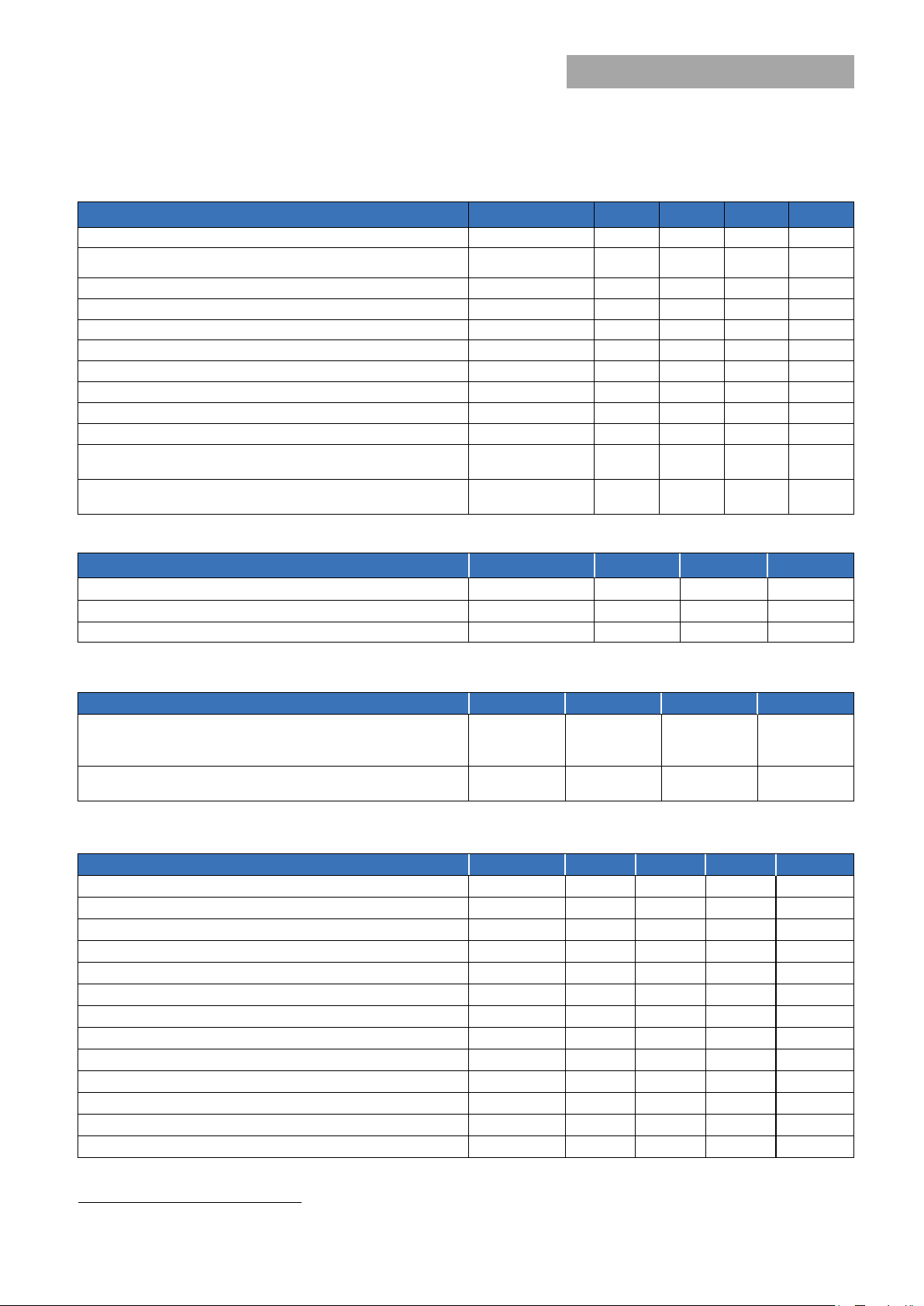
Figure 1. Power Supply Efficiency versus Output Current.
Figure 2. Derating Output Current versus Ambient
OUTPUT CURRENT, OUTPUT VOLTAGE
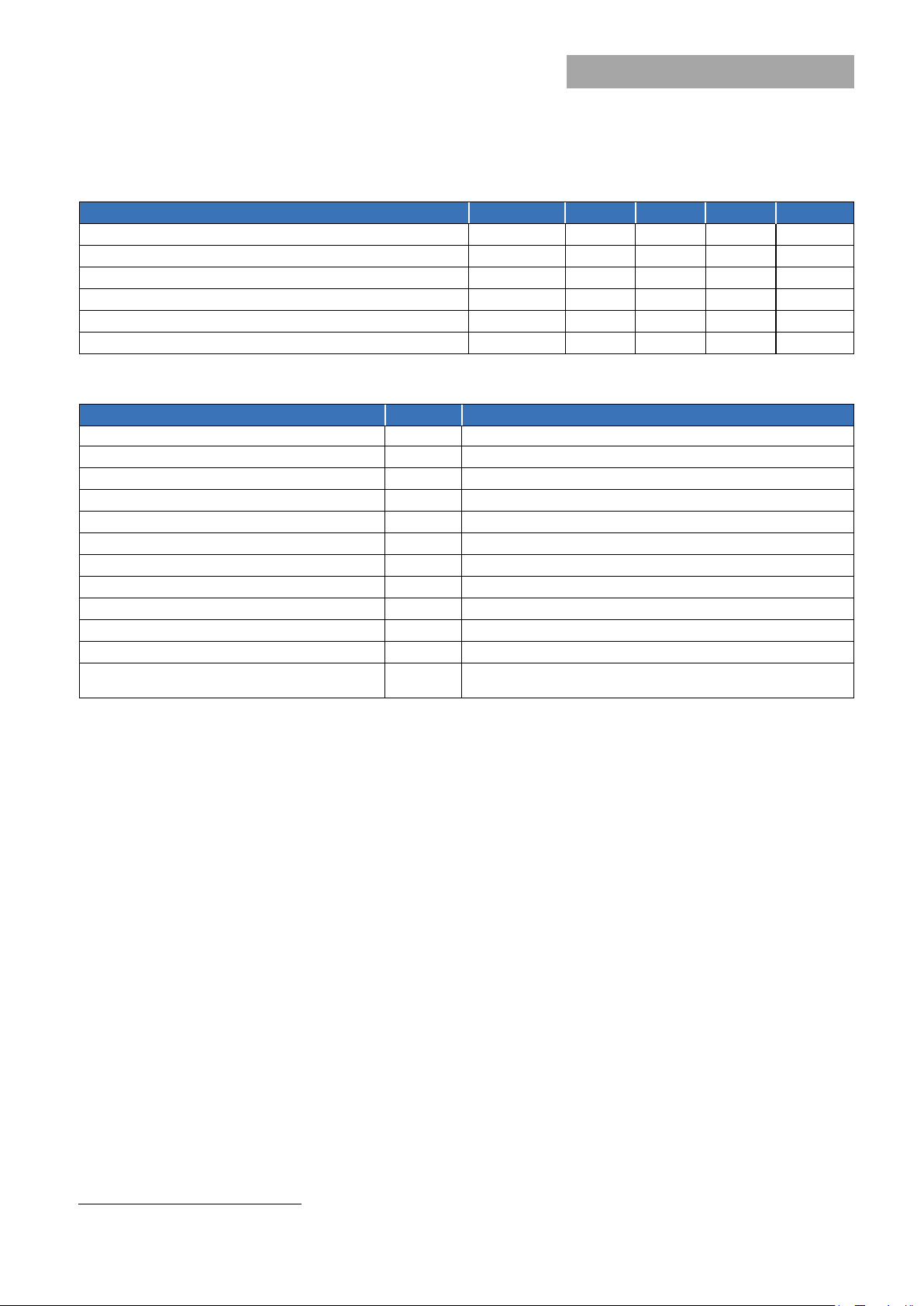
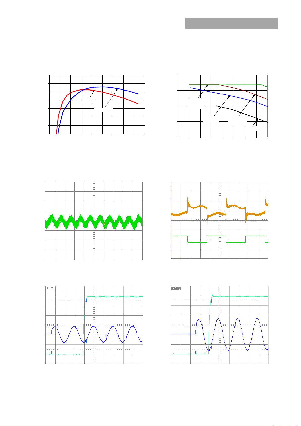
TIME, t (10ms/div)
TIME, t (5ms /div)
Figure 3. Typical output ripple and noise (VIN = 230Vac,
Figure 4. Transient Response to Dynamic Load Change from
OUTPUT VOLTAGE INPUT VOLTAGE
OUTPUT VOLTAGE INPUT VOLTAGE
Figure 5. Typical Start-up (VIN = 115Vac).
Figure 6. Typical Start-up (VIN = 230Vac)
80
82
84
86
88
90
92
94
0 2 4 6 8 10
12 14
16 18
Vin=115VAC
Vin=230VAC
0
5
10
15
20
30 35 40 45 50 55 60 65 70
0.5m/s
(100LFM)
2m/s
(400LFM)
1m/s
(
200LFM
)
NC
Characteristic Curves
The following figures provide typical characteristics for CLP0212 power supply
EFFICIENCY, η (%)
OUTPUT CURRENT, Io (A)
Temperature and Airflow. Data shown for 115VAC in, at
230VAC in derating is the same or better. For derating at
other input voltages, consult the GE Technical
representative.
Preliminary Data Sheet
(V) (50mV/div)
O
V
OUTPUT VOLTAGE
100% load ).
(V) (200V/div)
IN
(V) (2V/div) V
O
V
October 11, 2013 ©2012 General Electric Corporation. All rights reserved. Page 5
TIME, t (10ms/div) TIME, t (10ms/div)
(V) (100mV/div)
O
(A) (10Adiv) V
O
I
50% to 100% at Vin = 230Vac.
(V) (200V/div)
IN
(V) (2V/div) V
O
V
Page 6

GE
CLP0212 Open Frame Power Supply
90 - 264Vac input; 12Vdc output; 200W Output Power
OUTPUT VOLTAGE INPUT VOLTAGE
TIME, t (10ms/div)
TIME, t (10ms/div)
Figure 7. Typical Hold-up waveforms (VIN = 115V, 100%
Figure 8. Typical Hold-up waveforms (VIN = 230V, 100% load).
Characteristic Curves (cont.)
The following figures provide typical characteristics for CLP0212 power supply
Preliminary Data Sheet
OUTPUT VOLTAGE INPUT VOLTAGE
load).
(V) (200V/div)
IN
(V) (2V/div) V
O
V
(V) (200V/div)
IN
(V) (2V/div) V
O
V
October 11, 2013 ©2012 General Electric Corporation. All rights reserved. Page 6
Page 7

GE
CLP0212 Open Frame Power Supply
90 - 264Vac input; 12Vdc output; 200W Output Power
12
5
4
3.65K
1K
SWITCH
1 2
STANDBY OUTPUT
COM
ON/OFF
CLP POWER SUPPLY
Potentiometer
Safety Considerations
The
CLP0212
equipment
compliance with all
This
product is only for inclusion by professional installers
within other
stand-alone product. The power supply
IEC60950, EN60950,
60950 (Recognized
UL).
power supply is intended for inclusion in other
and the installer must ensure that it is in
the requirements
equipment
with the
Component)
and must
following
of the end application.
not
be
operated
meets
Class 1,
deviations:
C-UL
(Canadian Approval by
Nemko.
as a
UL
Feature Descriptions
Standby Power Supply
A standby output in the CLP0212 power supply of either 3.3
or 5V, comes on when AC input in the operating range is
applied. In the Z02A and Z03A versions of the power supply,
the standby output is not accessible.
Remote On/Off
All versions of the CLP0212 power supply except the Z02A
and Z03A versions feature a TTL-compatible On/Off control
input. The power supply turns ON when the On/Off input
goes low, and turns OFF when the input goes high. Note
that if the On/Off pin is left unconnected, the power supply
main output remains off.
Figure 9 shows the circuit configuration for using the On/Off
pin. Either a suitable semiconductor device such as a BJT or
FET or a mechanical switch can be used to turn the power
supply On and Off. The switch must be capable of handling
the On/Off pin current which may be up to 6mA when
closed. The switch On voltage drop must also be sufficiently
small so that the photo diode inside the power supply is
turned ON when the external switch is ON.
Note that the standby output voltage could be either 3.3V or
5V depending on the CLP0212 power supply variant
selected. If no On/Off control is desired, the On/Off pin can
be externally connected to the COM pin and the power
supply will automatically turn ON when AC input is within
range.
Preliminary Data Sheet
Output Voltage Adjustment
Fig. 10. Diagram showing location of the potentiometer
used to adjust the power supply output voltage.
The output voltage can be adjusted between 11.4V and 12.6V using a potentiometer on the power supply. See Fig. 10 for a diagram showing location of the potentiometer.
Remote Sense
The power supply has both positive and negative remote
sense connections that can be connected to the positive
and negative rails of the main output near the load. Care
should be taken in routing the sense lines to ensure that
noise is not picked up or that additional filtering elements
that affect the stability of the power supply are not used.
The power supply will operate without the remote sense
connections being made, however if remote sense near the
load is not used it is recommended that the remote sense
lines be connected directly to the main output terminals.
Overcurrent Protection
To provide protection in a fault condition (output overload), the
power supply is equipped with internal current-limiting
circuitry and can endure current limiting continuously. At the
point of current-limit inception, the unit enters hiccup mode.
The power supply operates normally once the output current is
brought back into its specified range.
Overvoltage Protection
Overvoltage protection is a feature of the CLP0212 power
supply that protects both the load and the power supply from
an output overvoltage condition. When an overvoltage occurs,
the power supply shuts down and goes into hiccup mode until
the overvoltage condition is removed. It is not necessary to
recycle the input to restart the power supply when this
protection is activated.
Fig. 9. Schematic showing ON/OFF circuitry.
October 11, 2013 ©2012 General Electric Corporation. All rights reserved. Page 7
Overtemperature Protection
The CLP0212 also features overtemperature protection in
order to provide additional protection in a fault condition. The
power supply is equipped with a thermal shutdown circuit
which detects excessive internal temperatures and shuts the
unit down. Once the power supply goes into overtemperature
shutdown, it will cool before attempting to restart. The
overtemperature protection circuit will typically activate when
the unit is operated at 200W output with an ambient
temperature of 60ºC and 1m/s (200LFM) airflow.
Page 8

GE
CLP0212 Open Frame Power Supply
90 - 264Vac input; 12Vdc output; 200W Output Power
Ambient Temperature (ºC)
Max. Output Power (W)
25
170
40
150
55
110
Enclosure Wall
Thermally Conductive Pad
Input Undervoltage Lockout
Preliminary Data Sheet
At input voltages below the input undervoltage lockout limit,
power supply operation is disabled. The power supply will
begin to operate at an input voltage above the undervoltage
lockout turn-on threshold. Note that the undervoltage lockout
limits are load dependent and the power supply turns ON and
can operate at much lower input voltage levels when at light
or no load.
DC OK
The CLP0212 provides a DC OK signal that indicates when
the output has come up and is in regulation. This is an opencollector type signal that goes high when the output is
available and within regulation.
Power Good LED
A green LED (located next to HDR3) illuminates when the main output voltage is above 10V.
Paralleling/Load Share
This power supply can be paralleled to provide larger load
currents than can be delivered from a single power supply. Up
to four power supplies may be paralleled. Paralleling is
accomplished by connecting the Current Share signals of
multiple power supplies together. At load current levels above
20%, the output currents of multiple power supplies will be
within ±5% of the full load value.
If remote sense is used when paralleling is employed, the
remote sense connection points should be common to both
power supplies.
For applications where redundancy among paralleled power
supplies is desired, ORing diodes or other active ORing circuitry
needs to be connected in series with each output.
Thermal Considerations
The power supply can be operated in a variety of thermal
environments; however sufficient cooling should be provided
to ensure reliable operation.
Considerations include ambient temperature, airflow, power
supply dissipation and the need for increased reliability. A
reduction in the operating temperature of the power supply
will result in increased reliability. The thermal data presented
here is based on measurements taken in a wind tunnel.
Heat Transfer via Convection
Increased airflow through the power supply enhances the heat
transfer via convection. Figure 11 shows the preferred airflow
direction. Contact your GE Energy technical representative for
derating information in other airflow directions.
Note: Under Natural Convection cooling conditions, the
maximum load is restricted to 100W as OTP will be triggered
at higher loads.
Fig. 11. Preferred airflow direction for cooling.
Operation In a Sealed Enclosure
The CLP0212 power supply can also be operated in a sealed
enclosure provided proper means for removing heat from the
power supply are used. Figure 12 shows an arrangement
where a thermally conductive pad is used to transfer heat
from the bottom of the power supply into the enclosure. Under
such conditions, the power supply is capable of reduced power
operation as shown in Table 1.
Fig. 12. Example arrangement of the CLP0212 for sealed
enclosure applications.
Table 1. Output Power Capability when the CLP0212 is
operated in a sealed enclosure with thermal pad for
conduction cooling.
.
October 11, 2013 ©2012 General Electric Corporation. All rights reserved. Page 8
Page 9

GE
Preliminary Data Sheet
CLP0212 Open Frame Power Supply
90 - 264Vac input; 12Vdc output; 200W Output Power
EMI performance
All CLP0212 power supplies are specified to meet conducted Class A EMI requirements per CISPR 22 (EN55022) with at least 3dB of
margin. Results of tests conducted without any external filtering are shown below. These indicate 10dB or better of margin over
the Class A limits.
CLP0212FPXX5Z01A (120VAC in, 12V @ 180W out, Negative of Output Grounded)
CLP0212FPXX5Z01A (208VAC in, 12V @ 180W out, Negative of Output Grounded)
October 11, 2013 ©2012 General Electric Corporation. All rights reserved. Page 9
Page 10

GE
Preliminary Data Sheet
CLP0212 Open Frame Power Supply
90 - 264Vac input; 12Vdc output; 200W Output Power
CLP0212FPEX5Z03A (120VAC in, 12V @ 180W out, Negative of Output Grounded)
CLP0212FPEX5Z03A (208VAC in, 12V @ 180W out, Negative of Output Grounded)
October 11, 2013 ©2012 General Electric Corporation. All rights reserved. Page 10
Page 11

GE
Preliminary Data Sheet
CLP0212 Open Frame Power Supply
90 - 264Vac input; 12Vdc output; 200W Output Power
Mechanical Outline (all except CLP0212…Z02A & CLP0212…Z03A versions)
Dimensions are in millimeters.
Tolerances: x.x mm ± 0.5mm [unless otherwise indicated]
x.xx mm ± 0.25mm
TOP VIEW
SIDE VIEW
3D-VIEW
October 11, 2013 ©2012 General Electric Corporation. All rights reserved. Page 11
Page 12

GE
CLP0212 Open Frame Power Supply
90 - 264Vac input; 12Vdc output; 200W Output Power
Mechanical Outline - CLP0212FPEXZ02A
Dimensions are in millimeters.
Tolerances: x.x mm ± 0.5mm [unless otherwise indicated]
x.xx mm ± 0.25mm
TOP VIEW
SIDE VIEW
3D-VIEW
Preliminary Data Sheet
October 11, 2013 ©2012 General Electric Corporation. All rights reserved. Page 12
Page 13

GE
CLP0212 Open Frame Power Supply
90 - 264Vac input; 12Vdc output; 200W Output Power
Mechanical Outline - CLP0212FPEX5Z03A
Dimensions are in millimeters.
Tolerances: x.x mm ± 0.5mm [unless otherwise indicated]
x.xx mm ± 0.25mm
TOP VIEW
SIDE VIEW
3D-VIEW
Preliminary Data Sheet
October 11, 2013 ©2012 General Electric Corporation. All rights reserved. Page 13
Page 14

GE
Preliminary Data Sheet
CLP0212 Open Frame Power Supply
90 - 264Vac input; 12Vdc output; 200W Output Power
AC Input Connector (HDR1)
DC Input Connector (HDR2)
Signal Connector (HDR3)
Connector Information
Connector Connector on Power Supply Mating Connector
AC Input Connector (HDR1) 5-1376382-1 from Tyco or equivalent 1376388-1 from Tyco or equivalent
DC Output Connector (HDR2) 39-28-1043 from Molex or equivalent 39-01-2040 from Molex or equivalent
Signal Connector (HDR3) 53047-0810 from Molex or equivalent 51021-0800 from Molex or equivalent
Pinout Information
Pin 1 Line Pin 1 VO Pin 1 Current Share
Pin 2 Neutral Pin 2 VO Pin 2 +S (Remote Sense +)
Pin 3 RTN Pin 3 -S (Remote Sense -)
Pin 4 RTN Pin 4 Remote On/Off
Pin 5 DC-OK (Output OK)
Pin 6 COM (Output Return)
Pin 7 COM (Output Return)
Pin 8 Standby Output
Note: Signal Connector HD3 is not present in the Z02A and Z03A versions.
October 11, 2013 ©2012 General Electric Corporation. All rights reserved. Page 14
Page 15

GE
Preliminary Data Sheet
CLP0212 Open Frame Power Supply
90 - 264Vac input; 12Vdc output; 200W Output Power
Contact Us
Input
Voltage Range
Output
Voltage
Output
Current
Standby
Supply
Temperature
Range
Ordering Information
Please contact your Lineage Power Sales Representative for pricing, availability and optional features.
Table 2. Device Codes
Device Code
CLP0212FPXX5Z01A 90 – 264Vac 12.0Vdc 16.7A Negative Logic 5V@0.25A -25 to 70ºC 150032000
CLP0212FPXX3Z01A 90 – 264Vac 12.0Vdc 16.7A Negative Logic 3.3V@0.25A -25 to 70ºC 150032001
CLP0212FPEX5Z01A 90 – 264Vac 12.0Vdc 16.7A Negative Logic 5V@0.25A -40 to 70ºC 150032002
CLP0212FPEXZ02A 90 – 264Vac 12.0Vdc 8.34A Absent Not accessible -40 to 70ºC 150032003
CLP0212FPEX5Z03A 90 – 264Vac 12.0Vdc 16.7A Absent Not accessible -40 to 70ºC 150032004
CLP0212FPXX5Z03A 90 – 264Vac 12.0Vdc 16.7A Absent Not accessible -25 to 70ºC 150032005
On/Off Control
Comcode
October 11, 2013 ©2012 General Electric Corporation. All rights reserved. Version 1.26
For more information, call us at
USA/Canada:
+1 888 546 3243, or +1 972 244 9288
Asia-Pacific:
+86.021.54279977*808
Europe, Middle-East and Africa:
+49.89.878067-280
India:
+91.80.28411633
www.gecriticalpower.com
 Loading...