

Page 1
H569-445 Battery Distribution Fuse/ Circuit
Breaker Bay (BDFB/BDCBB)
Product Manual
Comcode 850018552
Issue 3
June 2012
Page 2

Table of Contents
Customer Service Contacts ............................................................................................. 3
BDFB Overview ................................................................................................................ 4
Specifications .............................................................................................................. 5
Safety ......................................................................................................................... 6
Getting Started ........................................................................................................... 9
Floor Mounting ......................................................................................................... 12
Cabinet Extensions .................................................................................................... 13
Cabinet Top Cover ..................................................................................................... 14
Frame Ground ........................................................................................................... 15
Panel Positions and Labeling ..................................................................................... 17
Load Bus Arrangements ............................................................................................ 19
Distribution Panels ................................................................................................... 20
VIM1C Meter ............................................................................................................ 23
Alarm Connections and ABS Power ........................................................................... 27
Discharge Return Bus Options ................................................................................... 29
Adding/Moving Load Shunt Bus Details ..................................................................... 31
Wiring Schematics .................................................................................................... 35
Product Warranty ..................................................................................................... 37
Revision History ........................................................................................................ 39
Notice:
The information, specifications, and procedures in this manual are subject to change without
notice. Lineage Power assumes no responsibility for any errors that may appear in this
document.
© 2012 Lineage Power
All International Rights Reserved
Printed in U.S.A.
Page 3

Secondary DC Power Distribution Bay H569-445
Customer Service Contacts
For customers in the United States, Canada, Puerto Rico, and the US Virgin Islands, call
1-800-THE-1PWR (1-800-843-1797). This number is staffed from 7:00 am to 5:00 pm
Central Time (zone 6), Monday through Friday, on normal business days. At other times
this number contacts an answering service with on-call personnel for out of service
emergencies.
Customer Training
Lineage Power offers customer training on many Power Systems products. For
information call 1-877-LINEAGE (1-877-546-3243). This number is answered from 8:00
a.m. until 4:30 p.m., Central Time Zone (Zone 6), Monday through Friday.
Downloads and Software
To download the latest product information, visit our web site at
http://www.lineagepower.com/
Issue 3 June 2012 3
Page 4

Secondary DC Power Distribution Bay H569-445
BDFB Overview
This manual describes the H569-445 Secondary DC Power Distribution Bay. This Battery
Distribution Fuse Bay (BDFB) or Battery Distribution Circuit Breaker Bay (BDCCB) serves
as a secondary fuse or circuit breaker distribution center for -48V dc power delivered
from a central office battery plant.
Cabinet:
• 7-foot tall
• seismic zone 4
• extensions available for 9 and 11-1/2 foot applications
Load Buses
• up to six, 800A each
• each fed by a battery plant fuse or circuit breaker
• each feeding one or more Distribution Panels
Distribution Panels
• up to six, 28 positions each
• one or more Distribution Panels per Load Bus
• alarm lights and signals individual to each panel
Protectors
• Fuses or Circuit Breakers
• No position or spacing restrictions
• Fuses: TPS or TLS up to 125A
• Circuit Breakers up to 250A
Cabling
• Top or Bottom fed Input and Output cabling without reconfiguring the
cabinet.
Return Bars
• Optional internal 2-hole ground bars
• Optional external ground bars
mounted to overhead framing or cable rack
Monitoring - VIM1 Smart Monitor (standard)
• Voltage and Current of each load bus
or combined current of entire BDFB
• Alarm Status – Red backlight and LED
• Alarm Contacts: Fuse Alarm, Power Loss, Overload
• Redundantly Powered – Load Bus A and Load Bus B and ABS input
• Configurable for numerous BDFB applications
Issue 3 June 2012 4
Page 5

Secondary DC Power Distribution Bay H569-445
Specifications
Output Voltage: -48Volts DC
Output Capacity: 800A per Distribution Panel
6 Load BDFB: 2400A per Side, 4800A Maximum per Bay
4 Load BDFB: 1600A per Side, 3200A Maximum per Bay
2 Load BDFB: 800A per Side, 1600A Maximum per Bay
Agency Approval: UL Listed (cULus), NEBs
Environment: 0C to +40C (+32F to +104F)
Cabinet: Seismic Zone 4 Box Framework
Color: Central Office Soft Blue
Width: 26 inches (660mm) or 34 inches (864mm)
Height: 84 inches (2134mm)
Depth: 15 inches (381mm)
Weight: Approx. 375 pounds (6 panels)
Access: Front Fuse/Breaker and Alarm Access, Rear Wiring Access
Distribution: 28-Position Panel for Bullet-Style Protectors
Protectors:
• Bullet-Style Fuse Holders, TPS or TLS Fuses through 125A
• Single Pole LEL Bullet-Style Circuit Breakers through 100A
• Two-Pole LEL Bullet-Style Circuit Breakers through 150A
• Three-Pole LEL Bullet-Style Circuit Breakers through 250A
• No Protector Spacing Restrictions
• Maximum Loading
• 64% of protector rating - Continuous (List 1)
• 80% of protector rating - Maximum Load (List 2 - typically end of
discharge)
Accessories: External Ground Bar Assembly
Seismic Anchor Kits
Bullet-Style Fuse Holders, Fuses
Bullet-Style Circuit Breakers
2 ft Extension Cabinet for 9-ft application
4-1/2 ft Extension Cabinet for 11-1/2 ft applications
Top Cover for Bottom Feed Applications.
Issue 3 June 2012 5
Page 6

Secondary DC Power Distribution Bay H569-445
Safety
Safety Statements
Read and follow all safety instructions, warnings, and precautions in this manual and the manuals of all
equipment before installing, maintaining, or repairing the power system. Equipment manuals contain
additional safety statements, warnings, and precautions specific to the equipment.
• The H569-445 Secondary DC Power Distribution Bay is Underwriters Laboratories (UL) Listed per
Subject Letter 1801 (DC Power Distribution Centers for Telecommunications Equipment) for use
in the USA.
• Install only in restricted access areas (dedicated equipment rooms, equipment closets, or the like).
• Use this equipment in a controlled environment (an area where the humidity is maintained at levels
that cannot cause condensation on the equipment, the contaminating dust is controlled, and the
steady-state ambient temperature is within the range specified). Evaluated maximum ambient
temperature: 104°F (40°C).
• Do not install this equipment over combustible surfaces.
• Compression Connectors
• For installations in the U. S. or Canada, use Listed/Certified compression connectors to terminate
Listed/Certified field-wire conductors where required.
• For all installations, apply the appropriate connector to the correct size conductor as specified by
the connector manufacturer, using only the connector manufacturer’s recommended tooling or
tooling approved for that connector.
• If the proper connector for the country of installation is not provided, obtain appropriate
connectors and follow manufacturer’s and all local requirements for proper connections.
• The field wiring connections have been evaluated for connection of minimum 90°C conductors sized
per the U.S. National Electrical Code using 75°C ampacity tables.
• Torque electrical connections to the values specified on labels or in the product documentation.
• The short circuit current capability of the battery input to the distribution panel must not exceed
10,000 amperes.
• Use only fuses and circuit breakers specified in the product documentation to avoid possible in injury
to service personnel or equipment damage. They may not be provided with the equipment.
• Size fuses and circuit breakers as required by the National Electric Code (NEC) and/or local codes.
Refer to the equipment ratings to assure current does not exceed:
• Continuous Load (List 1) - 64% of protector rating
• Maximum Load (List 2 - typically end of discharge) - 80% of protector rating.
• Field-wired Conductors - Follow all National Electric Code (NEC) and local rules and regulations when
making field connections.
• Size field-wired conductors based on listed recommendations, National Electric Code (NEC)
and/or local codes based on 70°C ampacity.
• Insulation rating (minimum): 90°C; 105°C if internal to enclosed equipment cabinets.
• Dress cables to avoid undue stress on the connectors and damage to the conductors caused by
routing around sharp edges or routing in areas where wires could get pinched.
Issue 3 June 2012 6
Page 7

Secondary DC Power Distribution Bay H569-445
One of these two symbols (or equivalent) may be used to identify the
conductors with uninsulated metal objects. Follow safety precautions.”
One of these two symbols may be used to identify the presence of a hot
means that the part is or could be at hazardous voltage levels.
This symbol is used to identify the need for safety glasses and may
safety glasses.”
Warning and Safety Symbols
The symbols may sometimes be accompanied by some type of statement; e.g., “Hazardous
voltage/energy inside. Risk of injury. This unit must be accessed only by qualified
personnel.” Signal words as described below may also be used to indicate the level of
hazard
DANGER
WARNING
CAUTION
Indicates the presence of a hazard that will cause death or severe
personal injury if the hazard is not avoided.
Indicates the presence of a hazard that can cause death or severe
personal injury if the hazard is not avoided.
Indicates the presence of a hazard that will or can cause minor personal
injury or property damage if the hazard is not avoided.
This symbol identifies the need to refer to the equipment instructions
for important information.
These symbols (or equivalent) are used to identify the presence of
hazardous ac mains voltage.
This symbol is used to identify the presence of hazardous ac or dc
voltages. It may also be used to warn of hazardous energy levels.
presence of rectifier and battery voltages. The symbol may sometimes
be accompanied by some type of statement, for example: “Battery
voltage present. Risk of injury due to high current. Avoid contacting
surface. It may also be accompanied by a statement explaining the
hazard. A symbol like this with a lightning bolt through the hand also
This symbol is used to identify the protective safety earth ground for
the equipment.
This symbol is used to identify other bonding points within the
equipment.
sometimes be accompanied by some type of statement, for example:
“Fuses can cause arcing and sparks. Risk of eye injury. Always wear
Issue 3 June 2012 7
Page 8

Secondary DC Power Distribution Bay H569-445
Precautions
Read and follow these precautions.
• General precautions:
• Use only properly insulated tools.
• Remove all metallic objects (key chains, glasses, rings, watches, other jewelry, etc.).
• Wear safety glasses.
• Test circuits before touching.
• Lock out and tag circuit breakers/fuses when possible to prevent accidental turn on.
• Be aware of potential hazards before servicing equipment.
• Identify exposed hazardous electrical potentials on connectors, wiring, etc. (note the condition
of these circuits, especially wiring).
• Use care when removing or replacing covers; avoid contacting circuits.
• Use a personal ESD strap when accessing or removing electronic components.
• The equipment must be installed, serviced, and operated only by skilled, qualified personnel who
have the necessary knowledge and practical experience with electrical equipment and who
understand the hazards that can arise when working on this type of equipment.
• Exercise care and follow all safety warnings and practices when servicing this equipment. Hazardous
energy and voltages are present in the unit and on the interface cables that can shock or cause
serious injury.
• Batteries may be connected in parallel with the output of the rectifiers. Turning off the rectifiers will
not necessarily remove power from the bus. Make sure the battery power is also disconnected
and/or follow safety procedures while working on any equipment that contains hazardous
energy/voltage.
• Electricity produces magnetic fields that can affect implanted medical electronic devices, such as
pacemakers. The strength of the magnetic field depends on the amount of current in the circuit, as
well as other conditions (such as number of conductors, placement, and distance from the
conductor). DC power and distribution systems, including batteries, can operate at high current
levels. Personnel with electronic medical devices need to be aware of their restrictions when
working around electricity.
Issue 3 June 2012 8
Page 9

Secondary DC Power Distribution Bay H569-445
English
Screw Size
Torque (N-m)
Torque (in-lb)
6-32
1.1
10
10-32
2.8
30
1/4”-20
7.3
65
5/16-18
15
135
3/8”-16
27
240
Getting Started
Tools and Hardware
You will need the following tools and hardware to install the BDFB:
• Material-handling equipment to unload the cabinet at the installation site,
remove from shipping container, and set in final position [minimum lifting
capacity: 500 lbs. (227Kg)] Note: Use the equipment weights and dimensions as a
guideline for choosing material-handling equipment.
• Digital multimeter (DMM) with 0.05% accuracy on dc scale
• Insulated hand tools
• Screwdrivers (flat-blade and Phillips)
• Wire cutters and stripper
• Crimp Tools
• Drill and Drill Bits to install floor anchors
• Torque wrenches 25-720 in-lb
• Sockets: 5/16”, 7/16”, 9/16”, 3/4”, 15/16”, 19mm
Torque Setting for Hardware
Issue 3 June 2012 9
Page 10
Secondary DC Power Distribution Bay H569-445
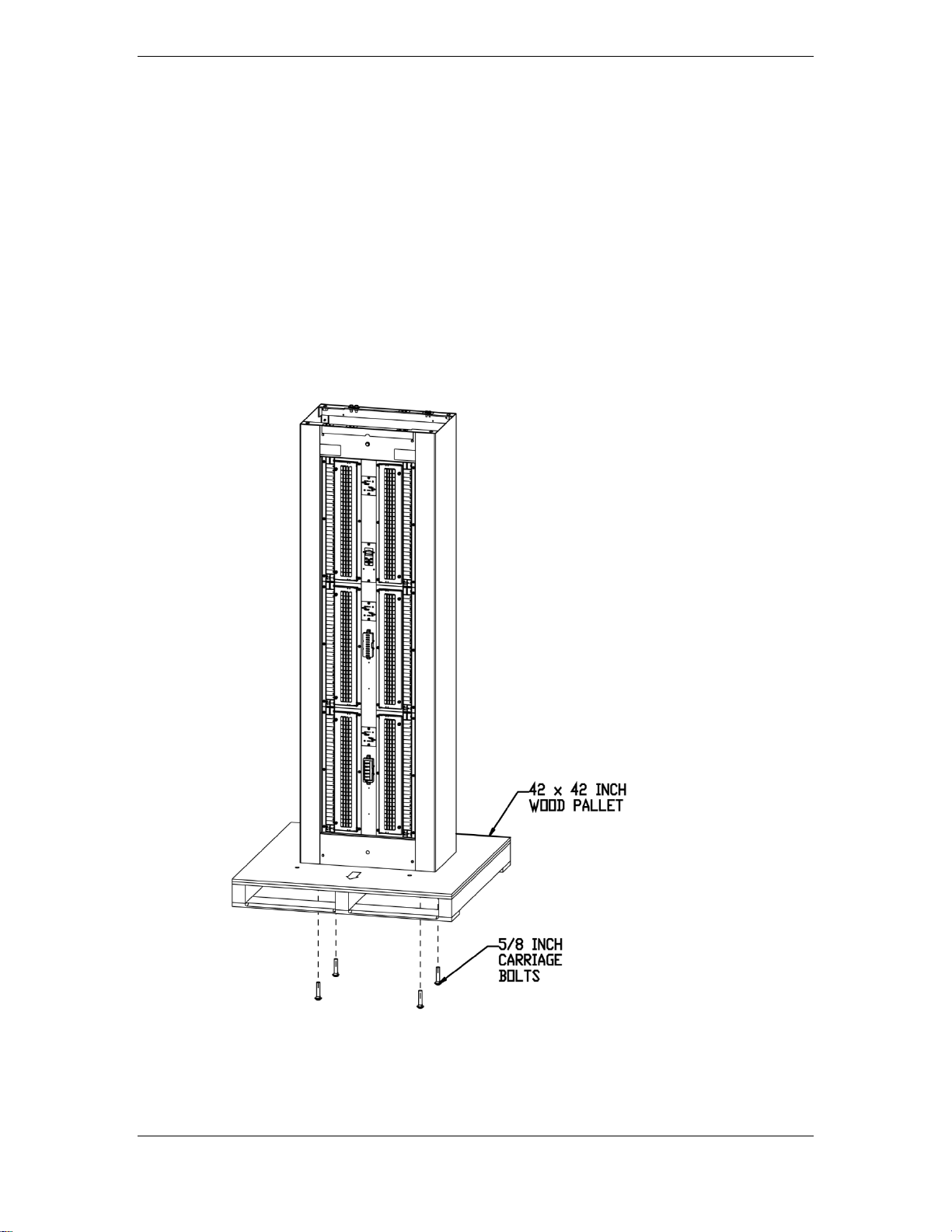
Unpacking BDFB
BDFB’s ship on a 42 by 42 inch skid as shown below. A 15/16 inch wrench or socket is
required to remove 5/8 inch diameter shipping bolts from skid. Before opening the
packaging, carefully inspect the outside in the presence of shipping personnel for signs
of damage. Carefully open the packaging to verify that the contents are complete and
undamaged. If damaged, follow the shipping carrier’s procedure for filing a damage
claim. If the equipment must be returned, repack in the original shipping packaging.
Before continuing, verify that the following conditions exist at the installation site:
• Floor is conditioned and clean (refers to removal of any combustible flooring, e.g.,
carpet, wood, etc.).
• Job Site Documentation details cabinet locations.
Figure 1 Cabinet Shipping Pallet
Issue 3 June 2012 10
Page 11
Secondary DC Power Distribution Bay H569-445
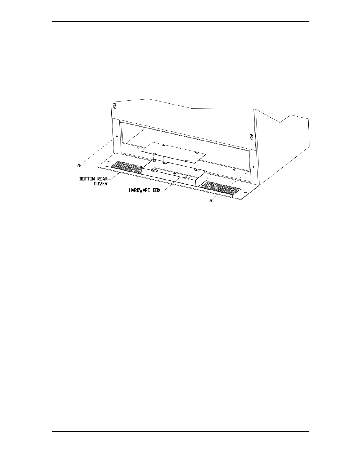
Unpacking Mounting Hardware
Hardware for making all cabled connections is included with the BDFB. 3/8 inch
hardware for Input Load Bus connections is installed on the Load Shunt and Load Return
Bus Details as shown in section 9. CC408576210 ¼ inch conical nuts are provided for all
output load and return connections. These nuts are located in the hardware box as
shown below.
Figure 2 Hardware Box Location
Issue 3 June 2012 11
Page 12
Secondary DC Power Distribution Bay H569-445
2” deep
(18 ft·lbs)
100mm deep
(60 ft·lbs)
Ordering Code
Description
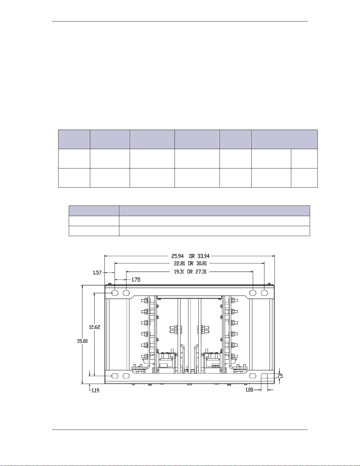
Floor Mounting
When installing the BDFB cabinet to the floor, the following mounting hardware may be
required depending on customer requirements.
• Drill anchor holes to depth specified in table below.
• Place floor insulation pad and/or use insulation bushings provided with anchors
if required.
• Shim under cabinet corners as necessary to level.
• Torque anchors as specified in table below.
Anchor Kits
Seismic
Zone
Ordering
Code
Anchor Type
(Hilti)
Hole
Size
Wrench Torque
0,1,2 847135662
0,1,2,3,4 847135688
Isolation and Leveling Kits
408520408 Floor Insulation Kit (16 in x 24 ¼ in)
CC109121588 Shim Kit
(4) 1/2 inch
drop-in
(4) 12 mm
cap bolts
5/8 inch bit
18mm bit
3/4 inch
19 mm
216 in·lbs
720 in·lbs
24.5
N·m
81.6
N·m
Figure 3 Footprint of Cabinets
Issue 3 June 2012 12
Page 13

Secondary DC Power Distribution Bay H569-445
Cabinet Extension Kits for 26-inch Wide Cabinet
848258588
4 -1/2 ft
11-1/5 ft
848258570
2 ft
9 ft
Frame
Ground
2’
4-1/2’
Frame
Ground
7’ Cabinet
7’ Cabinet
Cabinet Extensions
Optional cabinet extensions, constructed in the same manner as the 7 foot cabinet,
mount on top of the 26-inch wide cabinet to match the height of adjacent cabinets.
Kit Comcode Height Extension Height with Extension
Secure the cabinets together with four 5/8” bolts, lock washers and flat washers
(provided). Use a 15/16” socket.
Secure the interframe ground cable with two 7/16” bolts, lock washers, flat washers and
nuts (provided). Use 7/16” socket and wrench. This provides a continuous frame ground
to the top of the cabinet.
Mounting
Hardware
Figure 4 2-Foot or 4-1/2-Foot Extension Cabinet
Issue 3 June 2012 13
Strap
Mounting
Hardware
Strap
Page 14

Secondary DC Power Distribution Bay H569-445
848556908
5/8" x 1" Bolt (4 places)
Washer (4 places)
Cabinet Top Cover
When cabinets are used in bottom feed applications, an optional 848429288 top cover
kit may be installed on top of the 26-inch wide cabinet as shown below. Secure cover
with four 5/8” bolts and flat washers using a 15/16” socket.
802105304
Top Cover
802841759
Figure 5 Top Cover for Bottom-Feed Applications
Issue 3 June 2012 14
Page 15

Secondary DC Power Distribution Bay H569-445
Frame Ground
Frame ground connections are located on top of the cabinet. Connection is made using
either a 1/4 inch double-hole terminal lug on 0.625 inch centers or a 3/8 inch doublehole terminal lug on 1 inch centers. Landings are provided on both the front and rear
rails of the cabinet. Hardware is factory installed for these connections. Local grounding
practices will determine the grounding method and size of cable connected to the
cabinet.
Figure 6 Top View of 26-inch Wide Cabinet
Issue 3 June 2012 15
Page 16

Secondary DC Power Distribution Bay H569-445
Figure 7 Top View of 34-inch Wide Cabinet
Issue 3 June 2012 16
Page 17

Secondary DC Power Distribution Bay H569-445
Panel Positions and Labeling
The cabinet is configured for either top or bottom cable entry. The following figures
show the default labeling orientation used for top and bottom fed BDFB’s. Load Bus
designations (A, B, C, D, etc.) are stamped on the labels and the VIM1C meter is
programmed to reflect the Load Bus designations.
Some customers require a different labeling scheme so an extra set of 850018546 labels
is included to relabel the BDFB per local customer requirements. If the Load Bus
designations change, the VIM1C meter must identify the new location.
Menu ►Load Pa ram et er s ►First Load locates Load Bus A as upper-left, upper-
right, lower-left or lower-right. .
Menu ►Load Pa ram et er s ►Number of Loads identifies the number of load shunts
in the BDFB.
Figure 8 Top Feed BDFB
Issue 3 June 2012 17
Page 18

Secondary DC Power Distribution Bay H569-445
Figure 9 Bottom Feed BDFB
Issue 3 June 2012 18
Page 19

Secondary DC Power Distribution Bay H569-445
All bus bars are copper with a bright tin finish. Bus bars do not require buffing or
Load Bus Arrangements
A load bus is defined as one or more panels protected by a single circuit breaker or fuse
at the battery plant. Cable from the battery plant is terminated at Load Shunt Bus
Details rated for 800 amperes. (Two 750 kcmil feeder cables are required per shunt for
currents larger than 500 amps per shunt.) 3/8 inch hardware is provided for this
connection. The cabinet may be equipped for 2, 4 or 6 loads. In 2 or 4 load
configurations a bus bar link connects some panels together vertically. The 800 ampere
capacity per load bus applies even if multiple fuse panels are connected together.
When internal return buses are ordered, load return bus details will be located either at
the top or the bottom of the cabinet as shown depending on if a top cable feed or
bottom cable feed was ordered. These may easily be unbolted and moved if the
application requires. 3/8 inch hardware is provided for load return cables.
Note
the application of NO-OX before connection to terminal lugs or other bus bars.
Figure 10 Load Connection Points
Issue 3 June 2012 19
Page 20

Secondary DC Power Distribution Bay H569-445
Distribution Panels
Each 28-position distribution panel accepts bullet-style circuit breakers and fuseholders.
Single-pole breakers through 100A, two-pole breakers through 150A, three-pole
breakers through 250A and fuses to 125A may be installed in any position with no
spacing restrictions. Panels come with hinged front doors equipped with plastic slot
fillers. As circuit breakers or fuseholders are installed, un-snap the plastic slot filler and
replace with a circuit breaker or fuseholder. Store the excess plastic slot fillers in the
hardware bin in the back of the cabinet. Note: breakers/fuseholders can only be
installed one way or the front hinged door will not close properly. Each distribution
position has three alarm pin openings. The outer alarm opening is the alarm output.
Alarm pin of protector should insert into this opening. The inner two openings are
provided because some breaker styles have additional pins that require alarm power to
generate the output alarm.
Figure 11 Installing Breakers/Fuseholders
Issue 3 June 2012 20
Page 21

Secondary DC Power Distribution Bay H569-445
Figure 12 Distribution Connections
Issue 3 June 2012 21
Page 22

Secondary DC Power Distribution Bay H569-445
Two-pole breakers require two 850019325 2-pole adapter bus kits. Three-pole breakers
require two 850025679 3-pole adapter bus kits. They attach to the distribution panel as
shown below. The bus has 3/8-16 studs on 1 inch centers. Hardware is included.
Terminal lugs are sold separately.
Figure 13 Two-Pole and Three-Pole Adapter Bus Kits
Figure 14 Distribution Cable Routing
Issue 3 June 2012 22
Page 23

Secondary DC Power Distribution Bay H569-445
VIM1C Meter
Each load bus is equipped with a 1500 ampere shunt. The VIM1C monitors these shunts
to determine actual currents and the remaining capacity of each load bus.
VIM1C features include fuse/breaker alarms, power loss alarms, individually
configurable overload thresholds, individually configurable power loss, audible, and
remote form-C output alarms. The VIM1 receives redundant power from the A and B
panels and external ABS.
Voltage and Current - VIM1C displays voltage, current, and identifies each monitored load
1
.
bus
Alarm Indication - When an alarm occurs, the backlight on the display changes color from
green (normal) to red (alarm
Alarms” to “Alarms.”
Menus and Keys – Menus are structured with three main menu items: System
Parameters, Load Parameters, and Control/Operations - . Each key menu item has sub
items as shown in the menu map below. Left and Right keys are used to navigate the
menu. Up and Down keys are used to adjust the parameters. The VIM1C includes an
audible alarm with a user configurable on/off feature.
active) and the front panel text also changes from “No
Figure 15 VIM1 Smart Meter
1
The default VIM1 screen displays the label “Panel”, rather than “Load Bus”, before the Load Bus
identifier.
Issue 3 June 2012 23
Page 24

Secondary DC Power Distribution Bay H569-445
Figure 16 Meter Menu Map
Issue 3 June 2012 24
Page 25

Secondary DC Power Distribution Bay H569-445
measurement capability. These circuits are pre-wired with fixed positions in the BDFB. If
Programming the Meter
VIM1C parameters like shunt size and number of load buses are preconfigured when it is factory
installed in a BDFB. Only customer specific preferences need to be adjusted in the field. As a
replacement or meter upgrade, the factory default settings may need to be adjusted for the
application. Listed below are the configurable parameters and their associated factory defaults
available through the front panel. Following the table are the typical items that need to be
configured or verified in a retrofit or replacement application.
Item
1 System Voltage Factory default is 48V.
2 Local Buzzer Allows audible alarm to be Enabled or Disabled. Factory default is Disabled.
3
4 Software Version Displays the version of the application code running in the meter.
System
Parameters
Display Contrast
Description
Allows the display contrast to be adjusted for the local ambient lighting. Adjustable from 0100% in 1% increments. Factory default is 50%.
Load Parameters Description
5 Number Of Loads
6 Meter Type
7 Load ID Format
8 First Load (location)
9 Shunt Rating
10 Overload Latch
11 Combined Load
12 Load Available
13 Load Power Loss
14 Load Overload Type
15 Load Overload
16 Load Overload Delay
17 Assigned Circuits
Used to identify the number of individual loads/buses in the BDFB. Factory set from 1-8
depending on BDFB configuration.
Configures meter to display individual monitored bus voltages (voltage), voltages and
currents (volt_curr), or only currents (current). Factory default is Voltage and Current
(volt_curr).
Configures display format used in referencing individual DC loads/buses. Allowable
formats: A1, A, and 1. “A1” identifies loads using an A1, B1; A2, B2; … format. “A”
identifies loads using an A, B, C, D ... format. “1” identifies loads using a 1, 2, 3, 4 …
format. Factor Default is A format.
Used to indicate where the first load in the distribution is located. Allowable configurations
are: top-left, top-right, btm-left (bott om -l e ft), btm-right (bottom-right). Every monitored shunt
is considered a load. Factory default is determined by BDFB configuration.
Used to define the current rating of the shunt in the load bus. All shunts in the load must be
of the same size. A 50mV shunt is assumed. Allowable range is 1-4000A. The factory
default is 1500A in the BDFB.
A single configuration for all panels/buses that allows a temporary Over Load event to be
latched. Factory default is “Disabled”.
Displays the load value as one combined sum by adding up all shunts in the system and
presenting it as values for a single load. Factory default is disabled.
Indicates if the load is available or in use. Allowable configurations are “installed” and “not
installed”. “Installed” loads imply that the load is in use. “Not Installed” loads imply that the
load may be present, but it is not in use. Information obtained from the load should not be
relevant. Factor default is set to be “installed”.
The Power Loss (PL) alarm is triggered upon loss of the primary DC or when the
individual’s panels’ DC input has reached the configured low voltage threshold. This Power
Loss voltage threshold is configurable between 40.00-60.00V. Factory default is 40.00V.
The Power Overload Type defines whether the smart meter is to treat the Overload alarm
event for a “Single Bus” or for a “Redundant Bus” configuration. The “Single Bus”
configuration is based on straight Overload threshold being exceeded. The “Redundant
Bus” configuration causes the VIM1 to sum the two respective left and right load shunt
measurements and compare it to the individual overload thresholds configured for the each
of the respective panels in the pairing. The lowest Overload value threshold configured for
the Redundant loads shall take priority and be used in the comparison. Once the
“Redundant Bus” measurement exceeds this threshold, the controller asserts the Over
Load (OVL) alarm. Factor default is “Single Bus” configuration”.
The Load Overload (OVL) alarm event is triggered when any measured panel currents
exceed their respective configured thresholds. These OVL thresholds can be configured
from 1-4000A. Factory default is 800A.
An Overload Delay can be set to prevent nuisance alarms. This delay is configurable
between 0-300 seconds. Factory default is 0 seconds.
The VIM1 has eight individual load circuits with each circuit having voltage and shunt
Issue 3 June 2012 25
Page 26

Secondary DC Power Distribution Bay H569-445
circuit wiring from the VIM is redressed in the field this feature can be used to assign the
appropriate circuit to the new load location.
Control and
Item
Operations
Description
Parameters
18 Start Lamp Test
19 Clear Latched Events
20 Start Alarm Test
Cycles the illumination of the front panel LED and Backlight through Red, Amber, and
Green
Clears a latched Overload Alarm event. Note the Overload Latched Event must be enabled
to have a latched alarm.
Asserts Form-C alarms available at connector J3 in a fixed sequence: Fuse Alarm (FA),
Power Loss (PL), and Overload (OVL). Alarm asserted is displayed on the front panel.
Feature can be used to test the site’s remote monitoring systems and wiring.
Basic items to configure in a -48V meter retrofit or replacement
Use the previous VIM1C menu map and table as a reference to configure the basic items
listed below:
• Configure the Number Of Loads present in the BDFB (Item 5)
• Set the display Meter Type (Item 6)
• Configure the Load ID Format presented on the display (Item 7)
• Set the position of the First Load Location (Item 8)
• Configure the Shunt Rating of each monitored load in amps (Item 9)
• Set the state of each load as installed or not installed at Load Available (Item
12)
• Set the local audible alarm indicator capability at Local Buzzer (Item 2)
Issue 3 June 2012 26
Page 27

Secondary DC Power Distribution Bay H569-445
Alarm Connections and ABS Power
At the top of the cabinet is a Customer Interface Board for connecting Output Alarms
and Alarm Battery Supply (ABS) to redundantly power the alarms and the VIM1C meter.
The VIM1C receives redundant power from panels 1 and 2 as well as an external ABS
connection, so the ABS connection is not mandatory for proper operation but some
customers require its use. A Return connection is required for operation of the meter
and alarms. The Return connection on the Customer Interface Board is factory wired
when internal return buses are ordered, otherwise it must be field wired to the external
return bus. Alarm Outputs consist of one form-C contact for power loss, one form-C for
current overload and one form-C contact for fuse/breaker alarms (Note: there are two
connection points for FAJ/CB but they are connected to the same form-C contact).
Contacts are rated for 60V, 1/2A. Maximum wire size to the terminal blocks is 12 gage.
Figure 17 Accessing Customer Interface Board
Issue 3 June 2012 27
Page 28

Secondary DC Power Distribution Bay H569-445
Figure 18 Customer Interface Board
Issue 3 June 2012 28
Page 29

Secondary DC Power Distribution Bay H569-445
Discharge Return Bus Options
Discharge return bus options for terminating fuse or circuit breaker return leads may
either be internally mounted in the cabinet or externally mounted outside the
distribution bay on a cable rack.
Internal
The internal discharge return bus bar option terminates return cables from the battery
plant at the top (or bottom) of the cabinet as shown in Figure 12. There is a left-side bus
that interconnects to return bars mounted on the three left mounted fuse or circuit
breaker panels and a right-side bus for the right mounted panels. The bus at the top of
the cabinet is designed for terminating six 3/8 inch double-hole terminal lugs on 1 inch
centers with a tongue width up to 1.7 inches wide. Each panel mounted discharge
return bus is designed for terminating up to 2 gage cable with 1/4 inch double-hole
terminal lugs on 5/8 inch centers.
The advantage of internal returns is that load leads are paired at the fuse or circuit
breaker and eliminates the need for identification tags on each return lead. The
drawback to this cabling scheme is that you are limited to 1200 amps per side so for
multi-load BDFB’s requiring from 1200A-2400A capacity per side requires that input
returns must be located at the top and bottom of the cabinet with returns from the
battery plant split between the top and bottom bus bars. A second concern is the
potential cable congestion resulting from twice the number of leads in the distribution
bay. For these reasons, the internal discharge return option is recommended only for
applications with smaller ultimate capacities. For most applications, the external return
bus option is recommended.
External
The external discharge return bus bar options are shown in Figure 19 and Figure 20. The
external bus is mounted on a standard 15 or 20 inch ladder type cable rack. ED83019-50
Group 13 (150021156) and Group 13A (150021157) are rated for 2400 amperes of
current. Option 150021156 provides the first bus bar and the cable rack mounting
hardware. Option 150021157 provides a bus bar, the connecting bus bar and insulating
standoffs for stacking additional tiers as required. Refer to ED83019-50 drawing for
other ground bar options.
Issue 3 June 2012 29
Page 30

Secondary DC Power Distribution Bay H569-445
Figure 19 External Discharge Return Bus Options on Cable Rack
Figure 20 Bus Bar Hole Pattern and Numbering Schemes
Issue 3 June 2012 30
Page 31

Secondary DC Power Distribution Bay H569-445
Adding/Moving Load Shunt Bus Details
Sometimes it may be necessary to reconfigure a BDFB in the field. Two common
changes are converting two load BDFB’s from top feed configurations to bottom feed
configurations and changing from a 2-load to a 4 or 6-load BDFB. Additional Load Shunt
Bus Kits as shown on Figure 10 may be purchased separately.
Converting Top-Feed to Bottom-Feed
The following steps describe how to convert a top-feed cabinet to a bottom-feed
cabinet. Reverse this procedure to convert a bottom-feed to a top-feed cabinet.
1. Disconnect wires from the shunts on the load shunt assembly. Note the wire
colors and location. These same colors are used when moving the shunts from
panel position 1 to panel 5 position and panel position 2 to panel position 6. The
solid color (blue or slate) is closest to the input cables.
2. Disconnect the hardware securing the shunt assembly at the top of the cabinet.
3. Remove 6-32 screw securing shunt wires to the charge bus bar at the bottom of
the cabinet where the shunt assembly will be placed.
4. Relocate load shunt assembly and mount it in the bottom of the cabinet.
5. Connect shunt wires in same location and color as in previous location.
6. Connect shunt wires to the charge bus bar at the top of the cabinet where the
shunt assembly was removed using same 6-32 screw.
7. Move the internal return bus bar from the top to the bottom of the cabinet.
Note: Internal return bus bars may not be present.
8. The VIM1 meter needs to be reconfigured. Navigate to Menu ►Lo ad Paramet ers
►First Load
lower-right depending on which side you want to be side A and side B.
9. Relabeling might also be required as discussed in the Panel Positions and
Labeling section.
and change Load Bus A location from upper-left to lower-left or
Issue 3 June 2012 31
Page 32

Secondary DC Power Distribution Bay H569-445
Figure 21 Top-Feed to Bottom-Feed Cabinet Conversion
Issue 3 June 2012 32
Page 33

Secondary DC Power Distribution Bay H569-445
Converting from 2-Load to 4 or 6-Load
This requires that new load shunt bus kits be added to existing panels in the cabinet and
linking bus bars between panels be removed or “split” to create the additional loads.
The following steps describe this procedure.
Caution: Live potentials are present within a working BDFB/ BDCBB cabinet! Take
proper precautions to insulate all tools and prohibit any live surface from contacting
framework or any other grounded surface.
Note: If splitting existing loads within the BDFB/BDCBB, the load shunt assembly
will be at a live potential as soon as it comes into contact with a distribution panel
bus and must not be allowed to contact framework or any grounded surface during
or following this step!
1. Remove 6-32 screw securing shunt wires to the charge bus bar where the new
load shunt bus assembly will be installed. Note color of shunt wires at each
position.
2. Install load shunt bus assembly to the charge bus as shown in Figure 22. Connect
(2) red glastic standoffs to panel. Attach shunt detail to panels charge bus with
5/16 hardware provided and ½” socket (Torque to 135 in-lb) and attach to
standoffs with 1/4-20 screws provided and 7/16” socket (Torque to 65 in-lb).
3. Connect shunt wires to shunt. There should be a solid color like Blue, Orange,
Gray or Brown and a striped color like White-Blue, White-Orange, White-Gray or
White-Brown. Attach solid color to back connection (it is connected to input
bus). Attach striped color to front connection (it is connected to panels charge
bus).
4. Remove Bus Bar Straps to “split off” these panels as individual load buses.
Remove 5/16” hardware with ½” socket. Store these links in hardware bin in
back of cabinet.
5. The VIM1 meter needs to be reconfigured. Navigate to
Menu ►Load Parameters ►Number of Loads and set the number of load shunts
in the BDFB.
6. Relabeling might also be required as discussed in Section 8. Stamp or Label new
load designations on the labels.
Issue 3 June 2012 33
Page 34

Secondary DC Power Distribution Bay H569-445
Figure 22 2-Load to 6-Load Cabinet Conversion
Issue 3 June 2012 34
Page 35

Secondary DC Power Distribution Bay H569-445
Wiring Schematics
Figure 23 Panel Wiring Schematic
Issue 3 June 2012 35
Page 36

Secondary DC Power Distribution Bay H569-445
Figure 24 Alarm Wiring Schematic
Issue 3 June 2012 36
Page 37

Secondary DC Power Distribution Bay H569-445
Warranty Period
Product Type
New Product
Repaired Product*
Central Office Power
Equipment**
* The Warranty Period for a repaired Product or part thereof is six (6) months or, the
longer.
Product Warranty
A. Seller warrants to Customer only, that:
1 As of the date title to Products passes, Seller will have the right to sell, transfer, and
assign such Products and the title conveyed by Seller shall be good;
2 During the warranty period stated in Sub-Article B below, Seller’s Manufactured
Products (products manufactured by Seller), which have been paid for by Customer,
will conform to industry standards and Seller’s specifications and shall be free from
material defects;
3 With respect to Vendor items (items not manufactured by Seller), Seller warrants
that such Vendor items, which have been paid for by Customer, will be free from
material defects for a period of sixty (60) days commencing from the date of
shipment from Seller’s facility.
B. The Warranty Period listed below is applicable to Seller’s Manufactured Products
furnished pursuant to this Agreement, commencing from date of shipment from
Seller’s facility, unless otherwise agreed to in writing:
24 Months 6 Months
remainder of the unexpired term of the new Product Warranty Period, whichever is
C. If, under normal and proper use during the applicable Warranty Period, a defect or
nonconformity is identified in a Product and Customer notifies Seller in writing of such
defect or nonconformity promptly after Customer discovers such defect or
nonconformity, and follows Seller's instructions regarding return of defective or
nonconforming Products, Seller shall, at its option attempt first to repair or replace
such Product without charge at its facility or, if not feasible, provide a refund or credit
based on the original purchase price and installation charges if installed by Seller.
Where Seller has elected to repair a Seller’s Manufactured Product (other than Cable
and Wire Products) which has been installed by Seller and Seller ascertains that the
Product is not readily returnable for repair, Seller will repair the Product at
Customer’s site.
With respect to Cable and Wire Products manufactured by Seller which Seller elects to
repair but which are not readily returnable for repair, whether or not installed by
Seller, Seller at its option, may repair the cable and Wire Products at Customer’s site.
Issue 3 June 2012 37
Page 38

Secondary DC Power Distribution Bay H569-445
D. If Seller has elected to repair or replace a defective Product, Customer shall have the
option of removing and reinstalling or having Seller remove and reinstall the defective
or nonconforming Product. The cost of the removal and the reinstallation shall be
borne by Customer. With respect to Cable and Wire Products, Customer has the
further responsibility, at its expense, to make the Cable and Wire Products accessible
for repair or replacement and to restore the site. Products returned for repair or
replacement will be accepted by Seller only in accordance with its instructions and
procedures for such returns. The transportation expense associated with returning
such Product to Seller shall be borne by Customer. Seller shall pay the cost of
transportation of the repaired or replacing Product to the destination designated by
Customer.
E. Except for batteries, the defective or nonconforming Products or parts which are
replaced shall become Seller's property. Customer shall be solely responsible for the
disposition of any batteries.
F. If Seller determines that a Product for which warranty service is claimed is not
defective or nonconforming, Customer shall pay Seller all costs of handling,
inspecting, testing, and transportation and, if applicable, traveling and related
expenses.
G. Seller makes no warranty with respect to defective conditions or nonconformities
resulting from actions of anyone other than Seller or its subcontractors, caused by any
of the following: modifications, misuse, neglect, accident, or abuse; improper wiring,
repairing, splicing, alteration, installation, storage, or maintenance; use in a manner
not in accordance with Seller’s or Vendor’s specifications or operating instructions, or
failure of Customer to apply previously applicable Seller modifications and
corrections. In addition, Seller makes no warranty with respect to Products which
have had their serial numbers or month and year of manufacture removed, altered, or
experimental products or prototypes or with respect to expendable items, including,
without limitation, fuses, light bulbs, motor brushes, and the like. Seller’s warranty
does not extend to any system into which the Product is incorporated. This warranty
applies to Customer only and may not be assigned or extended by Customer to any of
its customers or other users of the Product.
THE FOREGOING WARRANTIES ARE EXCLUSIVE AND ARE IN LIEU OF ALL OTHER EXPRESS
AND IMPLIED WARRANTIES, INCLUDING BUT NOT LIMITED TO WARRANTIES OF
MERCHANTABILITY AND FITNESS FOR A PARTICULAR PURPOSE. CUSTOMER’S SOLE AND
EXCLUSIVE REMEDY SHALL BE SELLER’S OBLIGATION TO REPAIR, REPLACE, CREDIT, OR
REFUND AS SET FORTH ABOVE IN THIS WARRANTY.
Issue 3 June 2012 38
Page 39

Secondary DC Power Distribution Bay H569-445
Revision History
Issue 1 November 30, 2011
Initial release
Issue 2 December 15, 2011
Add External Return Bus Options 150021156 and 150021157.
Issue 3 June 7, 2011
Add References to 3-pole circuit breakers and 34-inch wide cabinet.
Issue 3 June 2012 39
 Loading...