

Page 1
DEH40155
g A-Series
II Panelboards
AD/AE/AQ Type P & N Power Panel
TEY Three-Phase Circuit Breaker Kits
Introduction
These instructions describe the installation of TEY three-phase circuit breaker kit into an
A-Series® II panelboard. These kits are for use in panelboards ordered with Un-Specified
Space. This kit requires minimum of X2, 12 inches of unspecified space.
The catalog number for twelve-pole TEY breaker kit is ASPP6EY12D
Parts List ASPP6EY12D Table 1.
ITEM # DESCRIPTION PART # QTY
1 A & C PHASE 200A STRAP 315A7049P10 4
2 STRAP, CENTER 315A7048P20 2
3 3X BRANCH BASE 911E347P3 2
4 THREAD ROLLING SCREW & WASHER 315A7034P6 6
5 FILLER PLATE, TEY 139C5503P129 1
6 SCREWS , #10-32 X 3/8 N722P16006B6 4
Installation
WARNING: Before attempting to install one of these kits, remove all power from the
panelboard.
Use the following procedure to install a TEY circuit breaker kit. Call-out numbers in the
illustrations and numbers in brackets in the text refer to the Item Numbers in Table 1.
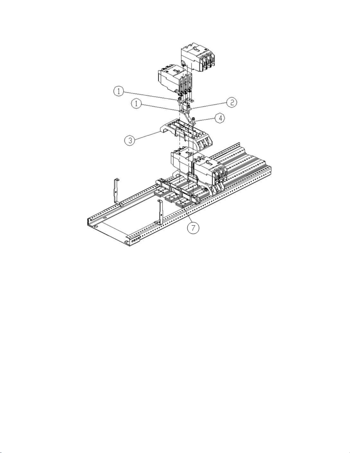
Installation of a three-pole kit is illustrated in Figure 1.
1. Remove the interior assembly from its packaging and verify that all parts are
present, as given in the parts list.
2. Remove the 8 screws (600A and 800A panels) securing the dead front to
panelboard interior. Lift off the dead front and place it and the screws aside.
3. Remove the circuit breaker kit from its packaging and verify that all parts are
present, as given in the packing list.
4. Refer fig no.1 to mount the breaker on interior. Place 3X base[3]adjacent to the
crossbar[7] to locate the mounting hole for the B phase strap [2]. Remove 3X base
[3] and screw the B phase Strap [2] into place using screw [4]. Then mount the
straps for A and C phase [1] into place using screws [4]. Similarly mount the
second 3X base straps and screws. All phase straps should be clamped with main
bus using screws [4] with a maximum of 60 in-lb torque.
®
DEH40155 Rev.No.02
1
Page 2
DEH40155
Figure 1. Installation of a TEY circuit breaker kit on left side of interior, catalog number
ASPP6EY12D, into an A-Series® II Panelboards.
5. Place the breaker as shown in fig.1 such that breaker strap hole aligns with
breaker mounting strap tapped hole and other end of breaker snaps with 3X base
lancing slot provided and then tighten terminal screws completely with 27-36 inlb.
6. Remove the eight screws [6] of existing two filler plates from dead front where
the TEY breaker needs to be installed, as illustrated in Figure 2
DEH40155 Rev.No.02
2
Page 3

DEH40155
Figure 2. Removing the shield inserts from the shield for TEY breaker installation in
A –Series® II Panelboards.
7. Place the filler plate [5] over the dead front so that the four same-size holes line
up with the threaded holes of the dead front, as illustrated in Figure 3. Fasten filler
3
plate to the dead front with four #10-32 x
/8 screws [6] tightened to 27-36 in-lb.
8. Reattach the dead front to the interior with the 8 screws removed in step 2.
Tighten the screws to 27-36 in-lb.
DEH40155 Rev.No.02
3
Page 4

DEH40155
Figure 3. Attaching the shield insert to the shield for TEY breaker installation in
A-Series® II Panelboards.
9. If TEY breakers has to be installed after SG or SF/TFJ or SE/TED/TQD as shown
in Figure 4 then gap between the breakers (dim A) has to be followed as
mentioned in Table 2. Replace the subsequent blank filler of dead front with TEY
filler plate given in kit ASPP6TEY12D using steps 9 to 11.
10. If TEY breaker has to installed immediate after crossbar as shown in Figure 5
then gap between the breaker and crossbar has to be 0.06inch.
DEH40155 Rev.No.02
4
Page 5

DEH40155
Figure 4. Distance between breakers
Breaker A (in)
SG 0.582
SF/TFJ 1.875
SE/TED(6P) 1.875
FB/TQD(6P) 1.875
Table 2. Distance between breakers.
DEH40155 Rev.No.02
5
Page 6

DEH40155
Figure 5. Distance between Crossbar and TEY breaker
These instructions do not cover all details or variations in equipment nor do they provide
for every possible contingency that may be met in connection with installation, operation,
or maintenance. Should further information be desired or should particular problems arise
that are not covered sufficiently for the purchaser’s purposes, the matter should be
referred to the GE Company.
DEH40155 Rev.No.02
6
 Loading...