

Page 1
DEH40150
g A-Series
®
II Panelboards
AD/AE/AQ Type P & N Power Panel
SG Three-Phase Circuit Breaker Kits
Introduction
These instructions describe the installation of SG three-phase circuit breaker kit into an
A-Series® II panelboard. These kits are for use in panelboards ordered with Un-Specified
Space.
The catalog number for three-pole kit is ASPP6SG3S
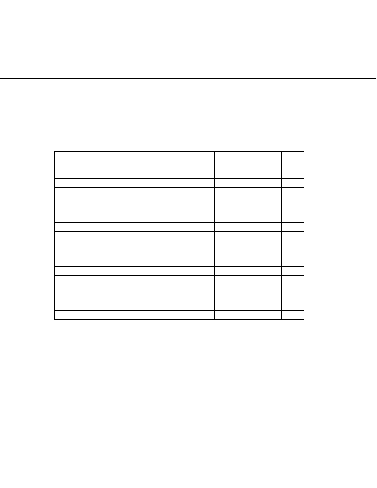
Part List for ASPP6SG3S Table 1.
ITEM # DESCRIPTION PART # QTY
1 STRAP FOR B PHASE 315A7046P8 1
2 STRAP FOR A PHASE 315A7046P7 1
3 STRAP FOR C PHASE 315A7046P9 1
4 (SPOOL) 315A7036P22 3
5 (SCREW-SPOOL) 315A7037P5 3
6 (WASHER-SPOOL) 75A105503P111 3
7 (SCREW-BUS) 315A7034P7 3
8 3P BRACKET 139C5500P83 1
9 SCREW, BKT TO RAIL N667P16008B6 2
10 XMAS TREE 315A7077P1 3
11 FILLER PLATE, SG/TFG 139C5503P103 1
12 SCREWS , #10-32 X 3/8 N722P16006B6 4
13 BRACKET INSULATION 10086929P11 1
14 INSULATOR B 10086929P5 1
15 INSULATOR A 10086929P7 1
16 INSULATOR C 10086929P6 1
17 BREAKER MOUNTING SCREWS N37P16060B6 2
19 SPRING LOCK WASHER #12 N405P40B6 2
Installation
WARNING: Before attempting to install one of these kits, remove all power from the
panelboard.
Use the following procedure to install a SG circuit breaker kit. Call-out numbers in the
illustrations and numbers in brackets in the text refer to the Item Numbers in Table 1.
Installation of a three-pole kit is illustrated in Fig.no.1 or Fig.no.2.
1. Remove the interior assembly from its packaging and verify that all parts are
present, as given in the parts list.
2. Remove the 8 screws (600A and 800A panels) securing the dead front to
panelboard interior. Lift off the dead front and place it and the screws aside.
3. Remove the circuit breaker kit from its packaging and verify that all parts are
present, as given in the packing list.
DEH40150 Rev.No.03
1
Page 2
DEH40150
4. Locate the holes on the B and C phase main busbar over which C phase of breaker
mounting strap will crossover the main busbar after assembly of the breaker in
horizontal position as shown in the Fig.no.1 or Fig.no.2. Put xmas [10] tree over
the two aligned holes of B and C phase.
5. Similarly locate the holes of A phase main busbar over which B phase of breaker
mounting strap will crossover the main busbar after assembly of the breaker in
horizontal position as shown in the Fig.no.1 or Fig.no.2. Put xmas [10] tree over
the aligned hole of A phase.
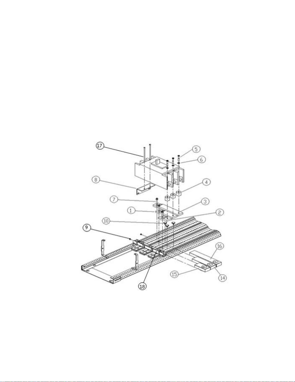
6. Refer Fig.no.1 to mount the breaker on left side of interior. First mount the strap
for A phase [2] adjacent to crossbar [18] and insert the screw [7] through slot
provided for A phase to clamp it with main busbar. Similarly mount B phase [1]
strap to B phase main busbar but adjacent to A phase branch base, and C phase
[3] strap to C phase main busbar but adjacent to B phase branch base. All the
phase straps [1], [2], and [3] should be clamped with main bus using screws [7]
with 60 in-lb maximum torque.
Figure 1. Installation of a SG circuit breaker kit on left side of interior, catalog number
®
ASPP6SG3S, into an A series
II panelboard.
7. Refer Fig.no.2 to mount the breaker on right side of interior. First mount the strap
for A phase [2] adjacent to cross bar [18] and insert the screw [7] through slot
provided for A phase to clamp it with main busbar. Similarly mount B phase [1]
strap to B phase main busbar but adjacent to A phase branch base, and C phase
DEH40150 Rev.No.03
2
Page 3

DEH40150
[3] strap to C phase main busbar but adjacent to B phase branch base. All the
phase [1],[2], and [3] straps should be clamped with main bus using screws [7]
with 60 in-lb maximum torque.
Figure 2. Installation of a SG circuit breaker kit on right side of interior, catalog number
ASPP6SG3S, into an A-Series® II panelboard.
8. Slide the insulator for A phase [15], B phase [14], C phase [16] cover over the
respective A, B, & C phase strap such that all the three insulators cut out made for
contact with the spool surface are in one line as shown in Fig.no.1 or Fig.no.2.
9. Mount bracket [8] on the interior rail with two screws [9] at the location defined
in Fig.no.1 and Fig.no.2 with 27-36 in-lb force.
3
10. Place the conical washer [6] over the three ¼-28 x 1
/8 screws [5] and insert the
screws through the holes in the top of the circuit breaker terminals. Secure the
three spools [4] to the underside of the breaker terminals with the screws [5].
Take care to assemble the screws to the spools as shown in Fig.no.1 or Fig.no.2,
with the tapped end of the spool toward the breaker terminal.
11. Tighten the three ¼-28 X 1 3/8 screws [5] to 50-70 lb-in.
12. Place the breaker over the straps [1], [2], and [3] such that screws [5] align with
strap holes as shown in Fig.no.1 and Fig.no.2. Put two screw [17] with spring lock
washer #12 [19] in the breaker as shown in Fig.no.1 and Fig.no.2. Tighten these
screws to bracket [8] with 18-22 lb-in torque.
13. Remove the four screws [12] of existing filler plate from dead front where the
pro-stock SG breaker needs to be installed, as illustrated in Fig.no.3.
DEH40150 Rev.No.03
3
Page 4

DEH40150
Figure 3. Removing the shield inserts from the shield for SG breaker installation in
A -Series® II panelboard.
14. To install branch breaker (kit ASPP6SG3S), place the new filler plate [11] over
the dead front so that the four same-size holes line up with the threaded holes of
the dead front, as illustrated in Fig.no.4. Fasten filler plate to the dead front with
four #10-32 x
3
/8 screws [12] tightened to 27-36 lb-in.
15. Reattach the dead front to the interior with the 8 screws removed in step 2.
Tighten the screws to 27-36 lb-in.
16. If SG breaker has to be installed immediate after cross bar as shown in Figure 5
then gap between the breaker and crossbar has to be 0.002 inch.
DEH40150 Rev.No.03
4
Page 5

DEH40150
Figure 4. Attaching the shield insert to the shield for SG breaker installation in A-Series®
II panelboards.
DEH40150 Rev.No.03
5
Page 6

DEH40150
Figure 5. Distance between Crossbar and SG breaker
These instructions do not cover all details or variations in equipment nor do they provide
for every possible contingency that may be met in connection with installation, operation,
or maintenance. Should further information be desired or should particular problems arise
that are not covered sufficiently for the purchaser’s purposes, the matter should be
referred to the GE Company.
g GE Industrial Systems
DEH40150 Rev.No.03
6
 Loading...