

Page 1
DEH40151
g A-Series
®
II Panelboards
AD/AE/AQ Type P & N Power Panel
SF Three-Phase Circuit Breaker Kits
Introduction
These instructions describe the installation of SF three-phase circuit breaker kit into an
A-Series® II panelboard. These kits are for use in panelboards ordered with Un-Specified
Space.
The catalog number for three-pole SF breaker kit is ASPP6SF3S
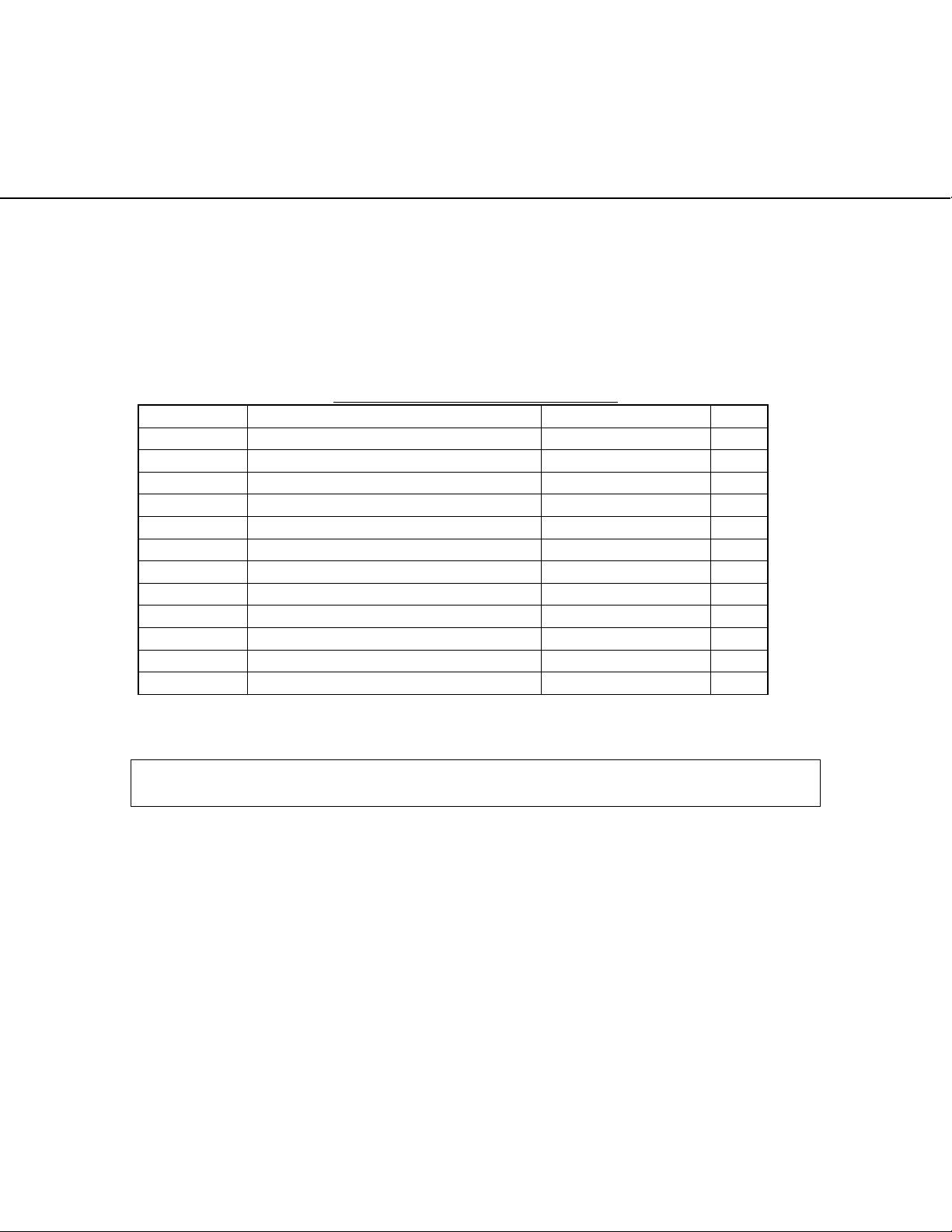
Parts List for ASPP6SF3S Table 1.
ITEM # DESCRIPTION PART # QTY
1 BRANCH BASE FOR B PHASE 139C5702BSFG1 1
2 BRANCH BASE FOR A PHASE 139C5702ASFG1 1
3 BRANCH BASE FOR C PHASE 139C5702CSFG1 1
4 (SPOOL) 315A7036P20 3
5 (SCREW-SPOOL) 315A7037P1 3
6 (WASHER-SPOOL) 75A105503P111 3
7 (SCREW-BUS) 315A7034P6 3
8 3P BRACKET 139C5500P84 1
9 SCREW, BKT TO RAIL N37P16060B6 2
10 CUP WASHER, N405P40B6 2
11 FILLER PLATE, SF/TFJ 139C5503P90 1
12 SCREWS , #10-32 X 3/8 N722P16006B6 4
Installation
WARNING: Before attempting to install one of these kits, remove all power from the
panelboard.
Use the following procedure to install a SF circuit breaker kit. Call-out numbers in the
illustrations and numbers in brackets in the text refer to the Item Numbers in Table 1.
Installation of a three-pole kit is illustrated in Figure 1 or Figure 2.
1. Remove the interior assembly from its packaging and verify that all parts are
present, as given in the parts list.
2. Remove the 8 screws (600A and 800A panels) securing the dead front to
panelboard interior. Lift off the dead front and place it and the screws aside.
3. Remove the circuit breaker kit from its packaging and verify that all parts are
present, as given in the packing list.
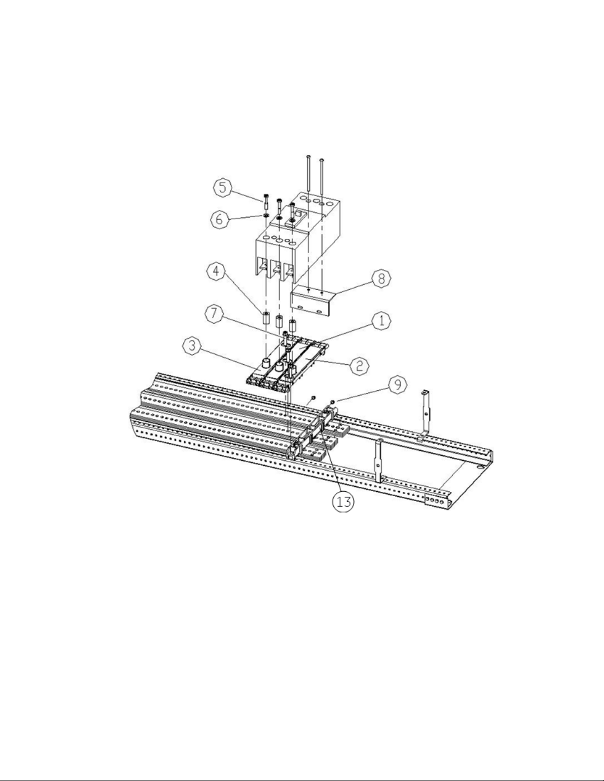
4. Refer fig. no.1 to mount the breaker on left side of interior. Place branch base for
A phase [2] adjacent to cross bar [13] as shown in fig.1 and insert the screw [7]
through slot provided for A phase to clamp it with main busbar. Similarly mount
DEH40151 Rev.No.02
1
Page 2
DEH40151
B phase [1] branch base to B phase main busbar but adjacent to A phase branch
base and C phase [3] branch base to C phase main busbar but adjacent to B phase
branch base as shown in fig. 1. All phase branch bases [1],[2] and [3] should be
clamped with main bus using screws[7] with 60 in-lb. Maximum.
Figure 1. Installation of a SF circuit breaker kit on left side of interior, catalog number
ASPP6SF3S, into an A-Series® II Panelboards.
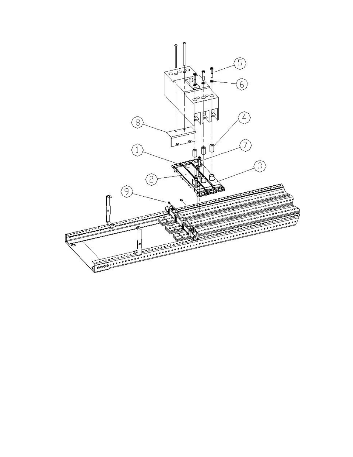
5. Refer fig. no.2 to mount the breaker on left side of interior. Place branch base for
A phase[2] adjacent to cross bar[13] as shown in fig.1 and insert the screw [7]
through slot provided for A phase to clamp it with main busbar. Similarly mount
B phase [1] branch busbar to B phase main busbar but adjacent to A phase branch
base and C phase [3] branch busbar to C phase main busbar but adjacent to B
phase branch base as shown in fig. 2. All phase branch bases [1],[2] and [3]
should be clamped with main bus using screws[7] with 50-70 in-lb.
DEH40151 Rev.No.02
2
Page 3
DEH40151
Figure 2. Installation of a SF circuit breaker kit on right side of interior, catalog number
ASPP6SF3S, into an A-Series® II Panelboards.
6. Mount bracket [8] on the interior rail with two screws [9] with 27-36 in-lb at the
location defined.
7. Place the conical washer [6] over the three ¼-28 x 1 3/8 screws [5] and insert the
screws through the holes in the top of the circuit breaker. Secure the three spools
[4] to the underside of the breaker terminal with the screws [5]. Take care to
assemble the screws to the spools as shown in Figure 1 or Figure 2, with the
tapped end of the spool toward the breaker terminal.
8. Place the breaker over branch base[1],[2] and [3], align the spool[4] with
protruded opening in branch bases and tighten the three ¼-28 X 1 3/8 screws [5]
installed in step 7 to 60 in-lb. Maximum.
9. Insert two screws [14] into the holes in the circuit breaker and tighten to bracket
[8] with 18-22 in-lb.
10. Remove the four screws [12] of existing filler plate from dead front where SF
breaker needs to be installed, as illustrated in Figure 3.
DEH40151 Rev.No.02
3
Page 4

DEH40151
Figure 3. Removing the shield inserts from the shield for SF breaker installation in
®
A –Series
II Panelboards.
11. To install branch breaker (kit ASPP6SF3S) on left side of interior, place the filler
plate [11] over the dead front so that the four same-size holes line up with the
threaded holes of the dead front, as illustrated in Figure 4. Fasten filler plate to the
dead front with four #10-32 x
3
/8 screws [12] tightened to 27-36 in-lb.
12. To install branch breaker (kit ASPP6SF3S) on right side of interior, flip filler
plate [11] and place it over the dead front so that the four same-size holes line up
with the threaded holes of the dead front, as similar to step 11. Fasten filler plate
3
to the dead front with four #10-32 x
/8 screws [12] tightened to 27-36 in-lb.
13. Reattach the dead front to the interior with the 8 screws removed in step 2.
Tighten the screws to 27-36 in-lb.
DEH40151 Rev.No.02
4
Page 5

DEH40151
Figure 4. Attaching the shield insert to the shield for SF breaker installation in
A-Series® II panelboards.
14. If SF breaker has to be installed after SG as shown in Figure 5 then gap between
the breakers (dim A) has to be followed as mentioned in Table 2. Replace the
subsequent blank filler of dead front with SF filler plate given in kit ASPP6SF3S
using steps 10 to 13.
15. If SF breaker has to be installed immediately after crossbar as shown in Figure 6
then gap between the breaker and crossbar has to be 0.061inch.
DEH40151 Rev.No.02
5
Page 6

DEH40151
Figure 5. Distance between breakers
Gap with
Breaker
SG 0.582
A (in)
Table 2. Distance between breakers.
DEH40151 Rev.No.02
6
Page 7

DEH40151
Figure 6 Distance between Crossbar and SF breaker
These instructions do not cover all details or variations in equipment nor do they provide
for every possible contingency that may be met in connection with installation, operation,
or maintenance. Should further information be desired or should particular problems arise
that are not covered sufficiently for the purchaser’s purposes, the matter should be
referred to the GE Company.
DEH40151 Rev.No.02
7
Page 8

DEH40151
g
GE Industrial Systems
DEH40151 Rev.No.02
8
 Loading...