

Page 1
g
p
g
quip
y
Application
These instructions apply to bolt-on circuit breaker kits
with catalog numbers AMCB3GM and AMCB2GM.
For use with circuit breaker types SGH, SGL, and SGP.
For use with circuit breaker cover kit AFP4SGS.
Replacement hardware kit: AHKBG1.
Installation
WARNING: Danger of electrical shock or injury.
OFF
Turn
switchboard before workin
e
Equipment is to be installed and maintained b
properly trained and qualified personnel only.
ower ahead of the panelboard or
inside the
ment or removing any component.
DEH060 Installation Instructions R04
Spectra Series™ Power Panelboards
Bolt-On Circuit Breaker Kits
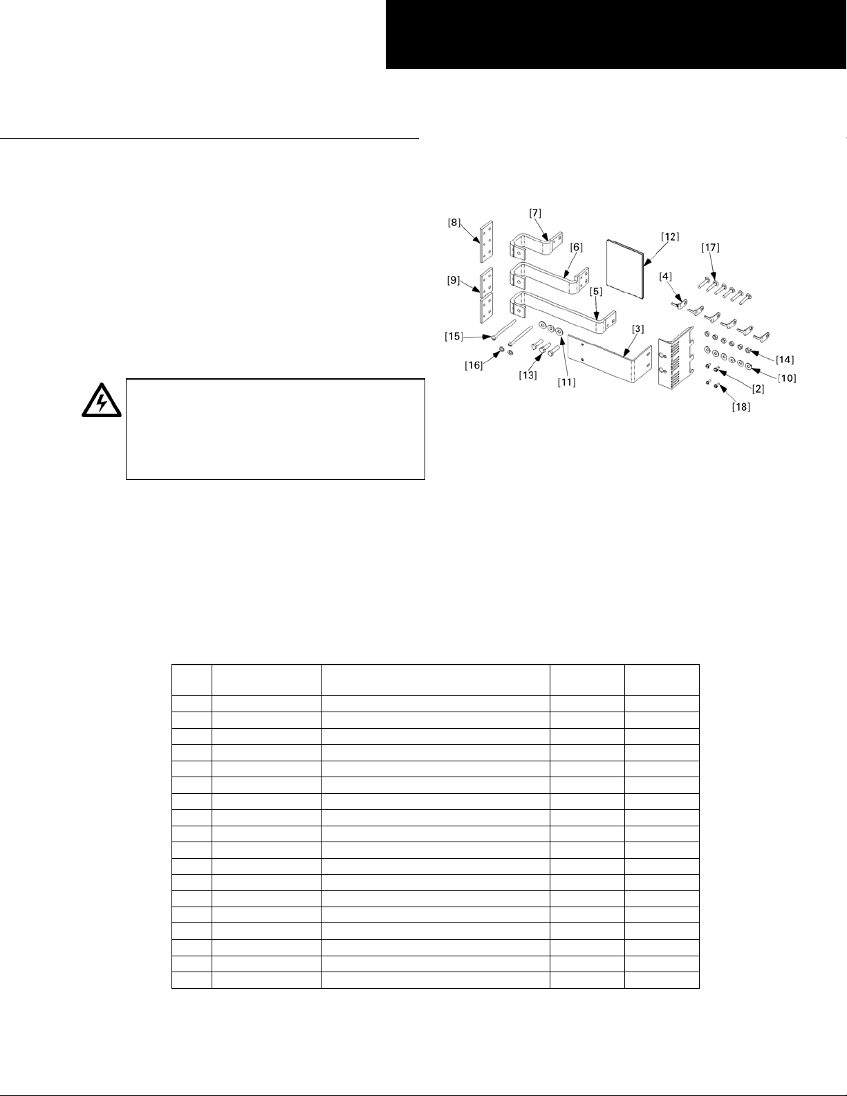
Figure 1. Parts included in the kits AMCB2GM and AMCB3GM.
In the following instructions numbers in brackets in the
text and figures refer to the items in Table 1.
1. Confirm the contents of the kit. These kits are used to
install main and single-branch G-frame Spectra circuit
breakers into Spectra APNB bolt-on–style interiors.
The vertical space required for each kit is 5.50 inches
(4X).
Figure 1 illustrates the parts included in this kit, which
are listed in Table 1.
Item Part # Description
1 10083041P1 Terminal cover 1 1
2 192A6976P189 Thread-forming screw, #10-32 x 7/16"2 2
3 252B3576P1 Circuit breaker mounting bracket 1 1
4 252B3613P1 Antiturn clip 4 6
5 252B3618G13 G frame single strap 1 1
6 252B3618G14 G frame single strap 1 1
7 252B3618G15 G frame single strap 1 1
8 252B3657P1 Spacer 1 1
9 252B3657P2 Spacer 2 2
10 75A105503P101 Conical spring washer, 1/4"46
11 75A105503P105 Conical spring washer, 5/16"23
12 DEH060 Installation instructions 1 1
13 N22P23016B6 Hex-head bolt, 3/8-16 x 1" 2 3
14 N245P21B6 Nut, 1/4-20 4 6
15 N37P21060B6 Screw, 1/4-20 x 33/4"22
16 N402P11B6 Flat washer, 1/4"22
17 N657P21024B6 Carriage bolt, 1/4-20 x 11/2"46
18 N730BP1308B6 Thread-forming screw, #6 x 1/2"22
Table 1. Parts list for kits AMCB2GM and AMCB3GM.
Qty. in
AMCB2GM
Qty. in
AMCB3GM.
Page 2
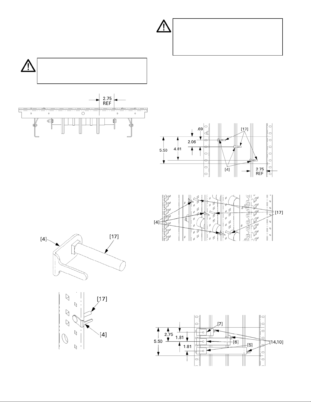
2. Locate the side of the interior with a 2.75-inch
g
prop
p
pp
reference distance. The circuit breaker straps are
mounted on the side of the panel interior bus at
which the distance from the vertical bus face to the
inner face of the bus-support rail is 2.75 inches, as
indicated in Figure 2.
NOTE: If the breaker cable connection is on
the same side of the interior as the 2.75"
reference dimension,
the cable connection is on the o
roceed with step 4. If
osite side of
the interior as the 2.75" reference dimension,
proceed to step 5.
NOTE: The following assembly views show the
2.75-inch distance on the ri
reference distance is on the left, the
ht. When this
er
view is upside down.
Figure 2. Illustration of the 2.75-inch reference distance.
3. Assemble antiturn clips onto carriage bolts. Slide an
antiturn clip [4] over the square shank of each
carriage bolt [17], as shown in Figure 3. Figure 4
illustrates the installation of a bolt and antiturn clip
onto the interior, as called for in the remaining steps.
When the breaker cable connection is on the same
side as the 2.75" reference dimension of the interior,
as illustrated in Figure 2, then only three each (for kit
AMCB3GM) or two each (for kit AMCB2GM) of items
[4] and [17] are used, with no spacers [8, 9]. When
the cable connections are on the opposite side, then
six each (for kit AMCB3GM) or four each (for kit
AMCB2GM) of items [4] and [17] are used, along
with spacers [8, 9].
4. Strap assembly procedure with cable connection on
the same side as the 2.75" distance. For single-phase
and dc applications using the bus closest to the bus
support, go to step 4c. For single-phase and dc
applications using the middle vertical bus and the
vertical bus on the opposite side of the 2.75" reference,
go to step 4e.
4a. For three-phase assembly (kit AMCB3GM).
Position the carriage bolt [17] and antiturn clip
[4] assemblies as shown in Figures 5 and 6.
Edge of G
Frame
Edge of G
Frame
Figure 5. Carriage bolt and antiturn clip installation for three-phase
connections.
Figure 3. Assembling an antiturn clip [4] with a carriage bolt [17].
Figure 4. Installing a carriage bolt [17] and antiturn clip [4] into the
interior.
Figure 6. Carriage bolt and antiturn clip installation for three-phase
connections, isometric view.
4b. Install straps. Place the G frame single straps [5, 6,
7] over the carriage bolts and antiturn clips, as
shown in Figures 7 and 8. Place conical washers
[10] on the bolts and secure with nuts [14]. Leave
the connections finger tight.
If the group assembly selection is three-phase,
with the cable connections on the same side as
the 2.75" reference dimension, and the assembly
looks like Figure 8, then go to step 6.
Edge of G
Frame
Edge of G
Frame
Figure 7. Installing the straps for three-phase connections.
2
Page 3
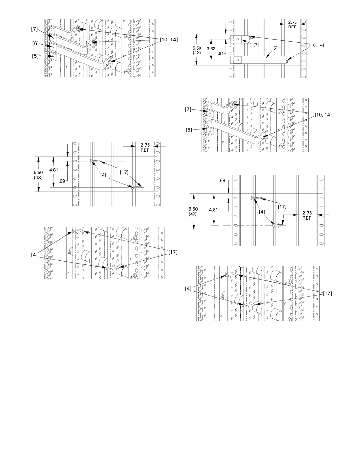
Figure 8. Installing the straps for three-phase connections, isometric
view.
4c. Connections to the outer bus of three-phase
interiors, with straps on single-phase interiors
using this assembly. For applications using the
center bus go to step 4e.
Position the carriage bolts [17] and antiturn clips
[4] as shown in Figures 9 and 10.
Edge of G
Frame
Edge of G
Frame
Edge of G
Frame
Edge of G
Frame
Figure 11. Installing the straps for connections to the outer bus of
three-phase interiors.
Figure 12. Installing the straps for connections to the outer bus of
three-phase interiors, isometric view.
Edge of G
Frame
Figure 9. Carriage bolt and antiturn clip installation for connections
to the outer bus of three-phase interiors.
Figure 10. Carriage bolt and antiturn clip installation for connections
to the outer bus of three-phase interiors, isometric view.
4d. Install straps. Place the G frame single straps [5,
7] over the carriage bolts and antiturn clips, as
shown in Figures 11 and 12. Place conical washers
[10] on the bolts and secure with nuts [14]. Leave
the connections finger tight.
If the group assembly selection is for connections
to the outer vertical bus with the cable
connections on the same side as the 2.75"
reference dimension, and the assembly looks like
Figure 12, then go to step 6.
4e. Strap connections to the middle vertical bus and
the vertical bus opposite the 2.75" reference
dimension.
Position the carriage bolts [17] and antiturn clips
[4] as shown in Figures 13 and 14.
Edge of G
Frame
Figure 13. Carriage bolt and antiturn clip installation for single-phase
applications with connections to the middle vertical bus.
Figure 14. Carriage bolt and antiturn clip installation for single-phase
applications with connections to the middle vertical bus, isometric
view.
4f. Install straps. Place the G frame single straps [6,
7] over the carriage bolts and antiturn clips, as
shown in Figures 15 and 16. Place conical washers
[10] on the bolts and secure with nuts [14]. Leave
the connections finger tight.
If the group assembly selection is for connections
to the outer vertical bus with the cable
connections opposite to the 2.75" reference
dimension, and the assembly looks like Figure 16,
then go to step 6.
3
Page 4

Edge of G
Frame
Edge of G
Frame
Figure 15. Installing the straps for single-phase applications with
connections to the middle vertical bus.
Figure 16. Installing the straps for single-phase applications with
connections to the middle vertical bus, isometric view.
5. Strap assembly procedure with cable connection on
the opposite side from the 2.75" distance. For single-
phase and dc applications using the bus closest to the
bus support, go to step 5c. For single-phase and dc
applications using the middle vertical bus and the
vertical bus on the opposite side of the 2.75" reference,
go to step 5e.
5a. For three-phase assembly (kit AMCB3GM).
Position the carriage bolts [17], antiturn clips [4],
and spacers [8, 9] as shown in Figures 17 and 18.
Figure 18. Carriage bolt and antiturn clip installation for three-phase
connections, isometric view.
5b. Install straps. Place the G frame single straps [5, 6,
7] over the carriage bolts and antiturn clips, as
shown in Figures 19 and 20. Place conical washers
[10] on the bolts and secure with nuts [14]. Leave
the connections finger tight.
If the group assembly selection is three-phase,
with the cable connections on the opposite side
from the 2.75" reference dimension, and the
assembly looks like Figure 20, then go to step 6.
Edge of G
Frame
Edge of G
Frame
Figure 19. Installing the straps for three-phase connnections.
Edge of G
Frame
Edge of G
Frame
Figure 17. Carriage bolt, antiturn clip, and spacer installation for
three-phase connnections.
Figure 20. Installing the straps for three-phase connnections,
isometric view.
5c. Connections to the outer bus of three-phase
interiors, with straps on single-phase interiors
using this assembly. For phase-balancing
applications using the center bus go to step 5e.
Position the carriage bolts [17], antiturn clips [4],
and spacers [9] as shown in Figures 21 and 22.
Place conical washers [10] on the bolts shown and
secure with nuts [14]. Leave the connections
finger tight.
4
Page 5

Edge of G
Frame
Edge of G
Frame
Figure 21. Carriage bolt, antiturn clip, and spacer installation for
connections to the outer bus of three-phase interiors.
Figure 22. Carriage bolt, antiturn clip, and spacer installation for
connections to the outer bus of three-phase interiors, isometric view.
Figure 24. Installing the straps for connections to the outer bus of
three-phase interiors, isometric view.
5e. Strap connections to the middle vertical bus and
the vertical bus on the same side as the 2.75"
reference dimension.
Position the carriage bolts [17], antiturn clips [4],
and spacers [8, 9] as shown in Figures 25 and 26.
Place conical washers [10] on the bolts shown and
secure with nuts [14]. Leave the connections
finger tight.
Edge of G Frame
5d. Install straps. Place the G frame single straps [5,
7] over the carriage bolts and antiturn clips, as
shown in Figures 23 and 24. Place conical washers
[10] on the bolts and secure with nuts [14]. Leave
the connections finger tight.
If the group assembly selection is for connections
to the outer vertical bus with the cable
connections on the opposite side from the 2.75"
reference dimension, and the assembly looks like
Figure 24, then go to step 6.
Edge of G Frame
Edge of G Frame
Figure 23. Installing the straps for connections to the outer bus of
three-phase interiors.
Edge of G Frame
Figure 25. Carriage bolt, antiturn clip, and spacer installation for
single-phase applications with connections to the middle vertical
bus.
Figure 26. Carriage bolt, antiturn clip, and spacer installation for
single-phase applications with connections to the middle vertical
bus, isometric view.
5f. Install straps. Place the G frame single straps [6,
7] over the carriage bolts and antiturn clips, as
shown in Figures 27 and 28. Place conical washers
[10] on the bolts and secure with nuts [14]. Leave
the connections finger tight.
If the group assembly selection is for connections
to the outer vertical bus with the cable
connections opposite to the 2.75" reference
dimension, and the assembly looks like Figure 28,
then go to step 6.
5
Page 6

Edge of G Frame
Edge of G Frame
Figure 27. Installing the straps for single-phase applications with
connections to the middle vertical bus.
Figure 28. Installing the straps for single-phase applications with
connections to the middle vertical bus, isometric view.
6. Install the circuit breaker mounting bracket. Secure
the breaker mounting bracket [3] to the panel side
rail with thread-forming screws [2]. Figures 29 and 30
show the installation for cable connections on the
same side as the the 2.75" reference dimension.
Figures 31 and 32 show the installation for cable
connections on the opposite side from the 2.75"
reference dimension. Tighten the thread-forming
screws to 30 in-lb.
7. Install circuit breakers. Figure 33 illustrates circuit
breaker installation. For main breaker operation,
position the device so that the load- or
OFF-side
terminals rest on the straps and the opposite side is
supported by the mounting bracket. For single-branch
operation, mount the breaker so that the line- or
ON-
side treminals rest on the straps and the opposite side
rests on the mounting bracket.
Align the holes in the breaker housing with the
corresponding holes in the mounting bracket. Fasten
the breaker to the bracket with the machine screws
[17] and flat washers [16] and tighten to 50 in-lb.
Attach the breaker terminals to the threaded holes in
the straps with the bolts [13] and conical washers
[11]. Tighten each terminal to 75 in-lb.
NOTE: Straps may require minor adjustments
for proper hole alignment.
Figure 29. Installing the breaker mounting bracket for cable
connections on the same side as the 2.75" reference dimension.
Figure 30. Installing the breaker mounting bracket for cable
connections on the same side as the 2.75" reference dimension,
isometric view.
Figure 31. Installing the breaker mounting bracket for cable
connections opposite the 2.75" reference dimension.
Figure 32. Installing the breaker mounting bracket for cable
connections opposite the 2.75" reference dimension, isometric view.
6
Page 7

Figure 33. Installing a circuit breaker.
8. Tigthen the bolted connections. Tighten the bolted
strap connections to the vertical bus to 65 in-lb. It may
be necessary to remove an adjacent breaker to allow
access to the bolted connections at the vertical bus.
9. Terminal cover installation. Install the terminal cover
[1] to the breaker with thread-cutting screws [18], as
3
shown in Figure 34. A
/8" x 3/8" relief hole must be
made in the cover if the breaker is mounted as a main
with an accessory cable (such as ground fault and
communications) leaving the load end of the breaker.
Cable connection on
2.75" reference side.
Figure 34. Installing the terminal cover on the breaker.
10. Breaker mounting configurations. For phasebalancing, single-phase panels, and dc applications,
refer to Figure 35 for the breaker mounting
configurations available with these strap kits. When
installing these strap configurations, be sure to use
standard phase rotation, as required.
3-pole main or
branch breaker,
A, B, & C
ø location.
2-pole main or
branch breaker,
A & C
ø location.
2-pole main or
branch breaker,
A & B
ø location.
3-pole main or
branch breaker,
A, B, & C
Cable connection
opposite to 2.75"
reference side.
2.75" REF
ø location.
2-pole main or
branch breaker,
A & C
ø location.
2-pole main or
branch breaker,
A & B
ø location.
Figure 35. Possible bus strap combinations. Note that if the 2.75" reference dimension is on the left side of the panel,
this diagram should be flipped 180° for the appropriate view.
7
Page 8

g
These instructions do not cover all details or variations in e
quip
y
p
ma
be met in connection with installation, operation, or maintenance. Should further information be desired or should
articular problems arise that are not covered sufficiently for the purchaser’s purposes, the matter should be referred to the
GE Company.
ment nor do they provide for every possible contingency that
GE Industrial Systems
General Electric Company
41 Woodford Ave., Plainville, CT 06062
DEH060 R04 0901 © 2001 General Electric Company
 Loading...