

Page 1

GE
AF-650 GP & AF-600 FP
TM
PROFINET
Operating Instructions
Page 2

Contents PROFINET Operating Instruction
Contents
1 Safety
1.1.2 Safety Note 3
1.1.3 Safety Regulations 3
1.1.4 Warning against Unintended Start 4
2 Introduction
2.1.1 About this Manual 5
2.1.2 Technical Overview 5
2.1.3 Assumptions 5
2.1.4 Hardware 5
2.1.5 Background Knowledge 5
2.1.6 Abbreviations 5
3 How to Install
3.1.1 How to Install Option in Frequency Converter
3.1.2 Network 7
3.1.3 PROFINET Cables 8
3.1.4 LED Behaviour
3
5
6
6
9
3.1.5 Topology 11
3.1.6 Recommended Design Rules 13
3.1.7 EMC Precautions
4 How to Configure
4.1.1 IP Settings 15
4.1.2 Ethernet Link Parameters 16
5 How to Configure the System
5.1 Configure the PROFINET Network
5.2 Configure the Controller
5.2.1 GSD File 17
5.3 Configure the Frequency Converter
5.3.1 Drive Parameters 21
6 How to Control the Frequency Converter
6.1 PPO Types
6.2 Process Data
6.2.3 Reference Handling
14
15
17
17
17
21
22
22
23
23
6.2.4 Process Control Operation 24
6.3 Control Profile
6.4 PROFIdrive Control Profile
6.5 GE Drive Control Profile
25
25
29
1
Page 3

Contents PROFINET Operating Instruction
7 PROFINET Acyclic Communication
7.1.1 Features of an IO Controller System 33
7.1.2 Features of an IO-Supervisor System 33
7.1.3 Addressing Scheme 34
7.1.4 Acyclic Read/Write Request Sequence 35
7.1.5 Data Structure in the Acyclic Telegrams 36
7.1.6 Header 36
7.1.7 Parameter Block 36
7.1.8 Data Block 36
7.1.9 Header 37
7.1.10 Data Block 37
8 Parameters
8.1 Parameter Group O-## Communication and Option
8.2 Parameter Group PB-## PROFIdrive
8.3 Parameter Group EN-## Ethernet
8.4 PROFINET-specific Parameter List
8.5 Object and Data Types Supported
33
38
38
40
42
45
47
9 Application Examples
9.1 E.g.: Process Data with PPO Type 6
9.2 E.g.: Control Word Network using Standard Telegram 1 / PPO3
9.3 E.g.: Status Word Network using Standard Telegram 1 / PPO3
9.4 E.g.: PLC Programming
10 Troubleshooting
10.1 Troubleshooting
10.1.1 LED Status 55
10.1.2 No Communication with the Drive 56
10.1.3 Warning 34 Appears even though Communication is Established
10.1.4 Will Not Respond to Control Signals 57
10.1.5 Alarm and Warning Words 60
11 Warnings and Alarms
11.1 Status Messages
11.1.1 Warnings/Alarm Messages 64
11.1.2 Alarm List 64
49
49
51
52
53
55
55
57
64
64
Index
2
67
Page 4

Safety PROFINET Operating Instruction
1Safety
1
1
1.1.1 Copyright, Limitation of Liability and
Revision Rights
This publication contains information proprietary to GE. By
accepting and using this manual the user agrees that the
information contained herein will be used solely for
operating equipment from GE or equipment from other
vendors provided that such equipment is intended for
communication with GE equipment over an serial
communication link. This publication is protected under
the Copyright laws of Denmark and most other countries.
GE does not guarantee that a software program produced
according to the guidelines provided in this manual will
function properly in every physical, hardware or software
environment.
Although GE has tested and reviewed the documentation
within this manual, GE gives no warranty or representation,
either express or implied, with respect to this documentation, including its quality, performance, or fitness for a
particular purpose.
In no event shall GE be liable for direct, indirect, special,
incidental, or consequential damages arising out of the
use, or the inability to use information contained in this
manual, even if advised of the possibility of such damages.
In particular, GE is not responsible for any costs including
but not limited to those incurred as a result of lost profits
or revenue, loss or damage of equipment, loss of computer
programs, loss of data, the costs to substitute these, or any
claims by third parties.
GE reserves the right to revise this publication at any time
and to make changes in its contents without prior notice
or any obligation to notify previous users of such revisions
or changes.
1.1.2 Safety Note
WARNING
HIGH VOLTAGE
The voltage of the frequency converter is dangerous
whenever connected to mains. Incorrect installation of the
motor, frequency converter or network may cause damage
to the equipment, serious personal injury or death.
Consequently, the instructions in this manual, as well as
national and local rules and safety regulations, must be
complied with.
1.1.3 Safety Regulations
1. The drive must be disconnected from mains if
repair work is to be carried out. Check that the
mains supply has been disconnected and that the
necessary time has passed before removing
motor and mains plugs.
2. The off-command on the serial bus does not
disconnect the equipment from mains and is thus
not to be used as a safety switch.
3. Correct protective earthing or grounding of the
equipment must be established, the user must be
protected against supply voltage, and the motor
must be protected against overload in
accordance with applicable national and local
regulations.
4. The earth leakage currents are higher than
3.5mA.
5. Do not remove the plugs for the motor and
mains supply while the drive is connected to
mains. Check that the mains supply has been
disconnected and that the necessary time has
passed before removing motor and mains plugs.
It has been assumed that all devices will be sitting behind
a firewall that does packet filtering and the environment
has wellimplemented restrictions on the software that can
run inside the firewall. All nodes are assumed to be
"trusted" nodes.
3
Page 5

Safety PROFINET Operating Instruction
1
1.1.4 Warning against Unintended Start
1. The motor can be brought to a stop by means of
bus commands while the drive is connected to
mains. If personal safety considerations make it
necessary to ensure that no unintended start
occurs, these stop functions are not sufficient.
2. While parameters are being changed, the motor
may start.
3. A motor that has been stopped may start if faults
occur in the electronics of the frequency
converter, or if a temporary overload or a fault in
the supply mains or the motor connection ceases.
WARNING
ELECTRICAL HAZARD
Touching the electrical parts may be fatal - even after the
equipment has been disconnected from mains.
4
Page 6

Introduction PROFINET Operating Instruction
2
2Introduction
2.1.1 About this Manual
First time users can obtain the most essential information
for quick installation and set-up in these chapters:
Introduction
How to Install
How to Configure the System
For more detailed information including the full range of
set-up options and diagnosis tools please refer to the
chapters:
How to Configure the System
How to Control the AF-600 FP/AF-650 GP
How to Access AF-600 FP/AF-650 GP Parameters
Parameters
Troubleshooting
Terminology:
In this manual several terms for Ethernet are used.
-PROFINET, is the term used to describe the
PROFINET protocol.
-Ethernet, is a common term used to describe the
physical layer of the network and does not relate
to the application protocol.
2.1.2 Technical Overview
Since its introduction in 2001, PROFINET has been updated
to handle low and medium performance requirement
supported by PROFINET RT (Real Time) up to High end
servo performance in PROFINET IRT (Isochronous Real
Time). With this, PROFINET is the Ethernet Based Fieldbus
offering the most scalable and versatile technology today.
PROFINET provides users with the network tools to deploy
standard Ethernet technology for manufacturing
applications while enabling Internet and enterprise
connectivity.
2.1.3 Assumptions
These operating instructions are under the conditions that
the GE PROFINET option is used in conjunction with a GE
AF-600 FP or AF-650 GP frequency converter. It is also
assumed that the installed controller supports the
interfaces described in this document and that all the
requirements stipulated in the controller, as well as the
frequency converter, are strictly observed along with all
limitations herein.
2.1.4 Hardware
2
This manual relates to the PROFINET option OPCPRT.
2.1.5 Background Knowledge
The GE PROFINET Option Card is designed to communicate
with any system complying with the PROFINET schema
version 2.2 standard. For earlier versions of PROFINET,
which support schema version 2.1 and earlier, GE
recommends an upgrade of the master and other devices
connected to the PROFINET network to schema version 2.2.
Familiarity with this technology is assumed. Issues
regarding hardware or software produced by other
manufacturers, including commissioning tools, are beyond
the scope of this manual, and are not the responsibility of
GE.
For information regarding commissioning tools, or
communication to a non-GE node, please consult the
appropriate manuals.
2.1.6 Abbreviations
Abbreviation Definition
API Actual Packet Interval
CC Control Card
CTW Control Word
DCP Discovery and Configuration Protocol
DHCP Dynamic Host Configuration Protocol
EMC Electromagnetic Compatibility
I/O Input/Output
IP Internet Protocol
GSD Generic station description
LED Light Emitting Diode
LSB Least Significant Bit
MAV Main Actual Value (actual output)
MSB Most Significant Bit
MRV Main Reference Value
N/A Not applicable
PC Personal Computer
PCD Process Control Data
PLC Programmable Logic Controller
PNU Parameter Number
REF Reference (= MRV)
RT Real Time
RTC Real Time Clock
STP Spanning tree Protocol
STW Status Word
Table 2.1
5
Page 7
3
How to Install PROFINET Operating Instruction
3How to Install
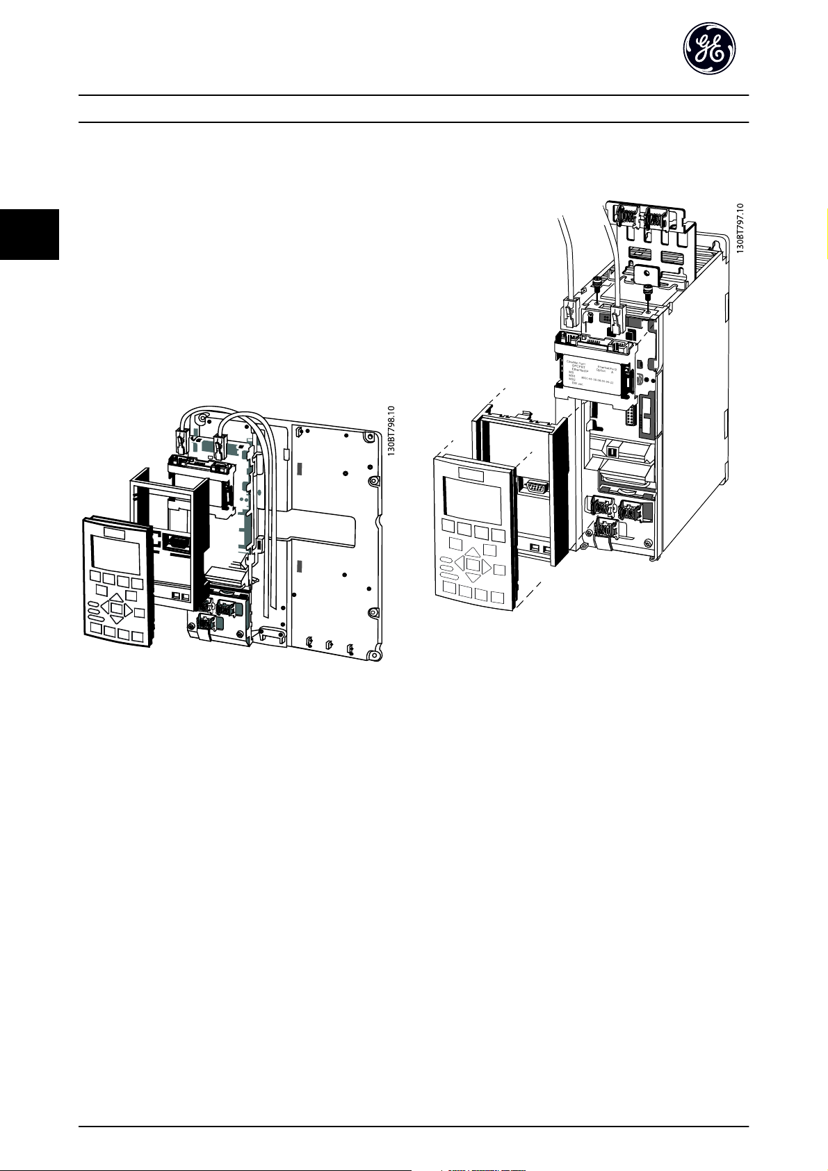
3.1.1 How to Install Option in Frequency
Converter
Items required for installing a network option in the
frequency converter:
- The network option
- Network option adaptor frame for the AF-600 FP/
AF-650 GP. This frame is deeper than the
standard frame, to allow space for the network
option beneath
- Strain relief (only for unit sizes 11 and 12)
Illustration 3.1
Illustration 3.2
Instructions:
- Remove keypad panel from the AF-600 FP/AF-650
GP.
- Remove the frame located beneath and discard it.
- Push the option into place. The Ethernet
connectors must be facing upwards.
- Remove both knock-outs on the network option
adaptor frame.
- Push the network option adaptor frame for the
AF-600 FP/AF-650 GP into place.
- Replace the keypad and attach cable
NOTE
Do not strip the Ethernet cable and ground it via the strain
relief-plate! The grounding of screened Ethernet cable is
done through the RJ-45 connector on the option.
NOTE
After installing the OPCPRT option, be aware of the
following parameter settings:
O-01 Control Site: [2] Controlword only or [0] Digital and ctrl.
word
O-02 Control Word Source: [3] Option A
6
Page 8

How to Install PROFINET Operating Instruction
3
3.1.2 Network
It is of high importance that the media chosen for Ethernet
data transmission are suitable. Usually CAT 5e and 6 cables
are recommended for industrial applications. Both types
are available as Unshielded Twisted Pair and Shielded
Twisted Pair. Generally shielded cables are recommended
for use in industrial environments and with frequency
converters.
A maximum cable-length of 100m is allowed between
switches.
Optical fibres can be used for gapping longer distances
and providing galvanic isolation.
For connecting PROFINET devices both hubs and switches
can be used. It is, however, recommended always to use
suitable industrial graded Ethernet switches. GE
recommends always to use PROFINET compliant switches
3
7
Page 9

3
How to Install PROFINET Operating Instruction
3.1.3 PROFINET Cables
PROFINET cables used are based electrically on category 5 balanced LAN cables according to ISO/IEC 11801 Edition 2.0, Class
D.
Type C cables can be used in special applications (e.g. the use of trailing cables and frequently moved machine parts) even
though their design and mechanical parameters can deviate from the specifications of type A and type B cables. Still most
of the electrical parameters (impedance levels etc.) are retained. Highly flexible copper cables generally have the finest
stranded conductors and, for example, a highly resistant polyurethane outer sheath.
Various outer sheath materials are permitted in order to meet the various demands with regard to resistance of industrial
environments and exterior/underground laying (natural and synthetic oil, grease, coolants/lubricants, chemicals, high and
low temperatures, UV radiation).
All balanced cables used shall comply with the following parameters:
Cable Type Application Type A Application Type B Application Type C
Design Data Cable Data Cable Data Cable
Cable Installation Type Stationary, no movement
after installation
Cable Marking PROFINET Type A PROFINET Type B PROFINET Type C
Core Cross Section AWG 22/1 AWG 22/7 AWG 22/..
Outer Diameter 5,5 - 8,0 mm Application
Core Diameter 1,5 +/- 0,1 mm Application
Colour (Outer Sheath) Green RAL6018 Application
Core Identification (colours) star
quad 2 pair
Number of Cores 4
Cable Design 2 pairs or 1 star quad
Shielding Design Type Aluminum Foil + Cu braiding Application
Which Plug for which Cable Type RJ45 (IP 20 or IP 65/67) / M12
white, yellow, blue, orange Pair 1: white (RXD+), blue (RXD-) Pair 2: yellow(TXD+), orange(TXT-)
Flexible, occasional movement
or vibration
Special Applications (e.g. highly flexible,
permanent movement, vibration or torsion)
Table 3.1
Transmission Performance Requirements:
Relevant Standard ISO/IEC 11801 Edition 2.0, IEC 61156
(minimum Category 5)
Delay Skew <=20ns/100m
Transfer Impedance <=50mOhm/m at 10MHz
Table 3.2
8
Page 10
How to Install PROFINET Operating Instruction
3
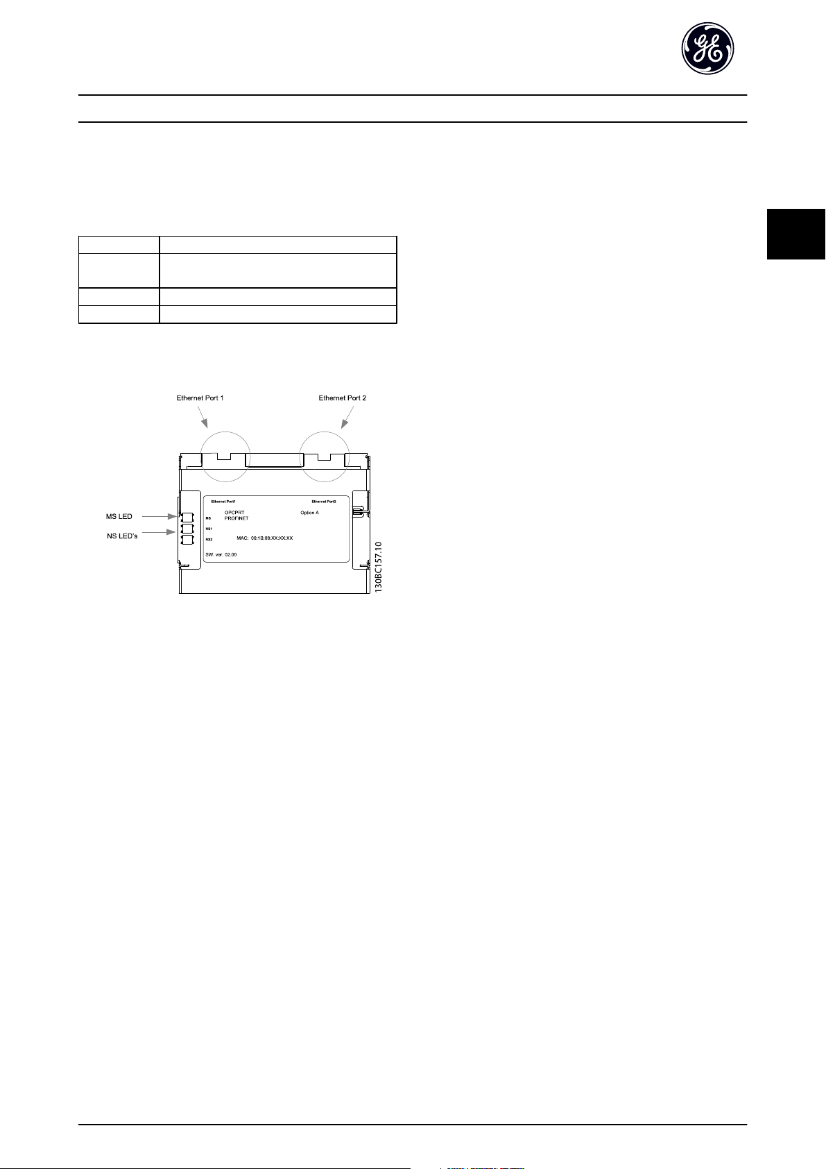
3.1.4 LED Behaviour
The option has 3 bi-coloured LEDs that allow a fast and
detailed diagnosis. The three LEDs are each linked to its
unique part of the PROFINET option:
LED Label Description
MS Module Status, reflects the activity on the
PROFINET stack
NS1 Network Status 1, reflects the activity on port 1
NS2 Network Status 2, reflects the activity on port 2
Table 3.3
Illustration 3.3 Overview of the Option
3
9
Page 11
3
How to Install PROFINET Operating Instruction
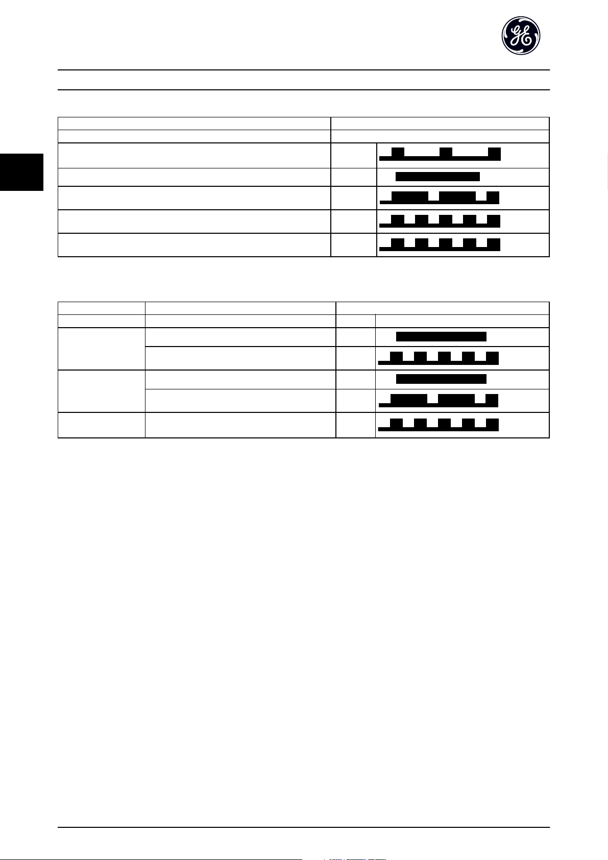
Module Status
Status Tri-colour LED
No IP Address assigned Off
No Communication to PROFINET module. Module is waiting for configu-
ration telegram from Controller.
IO AR established Green:
Supervisor AR established, No IO AR. Green:
Internal Error Red:
Green:
Wink
Table 3.4 MS: Module Status
Yellow:
Network Status
Phases Status Tri-colour LED
Power Off No Power or No Link on the corresponding port Off
IP Address Conflict Red:
Power On
Running
Data exchange
Table 3.5 Indication on Network Status LED
Waiting for configuration Green:
In Data Exchange Mode Green:
Wrong Configuration Red:
No increment in "In Octets" counter of
corresponding port in last 60 secs.
Yellow:
During normal operation the MS and at least one NS LED will show a constant green light.
Wink command
The option will responds to a Wink command from the network by yellow flashing of all three LEDs simultaneously.
10
Page 12
How to Install PROFINET Operating Instruction
3
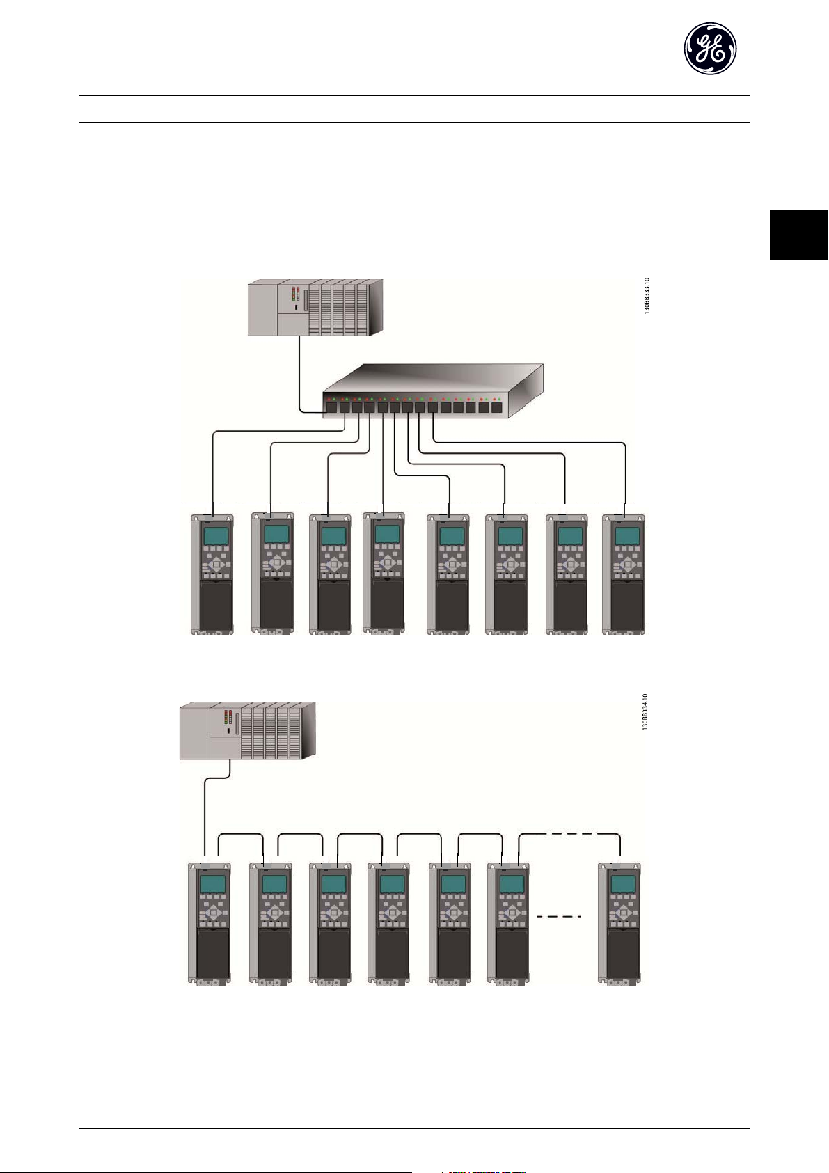
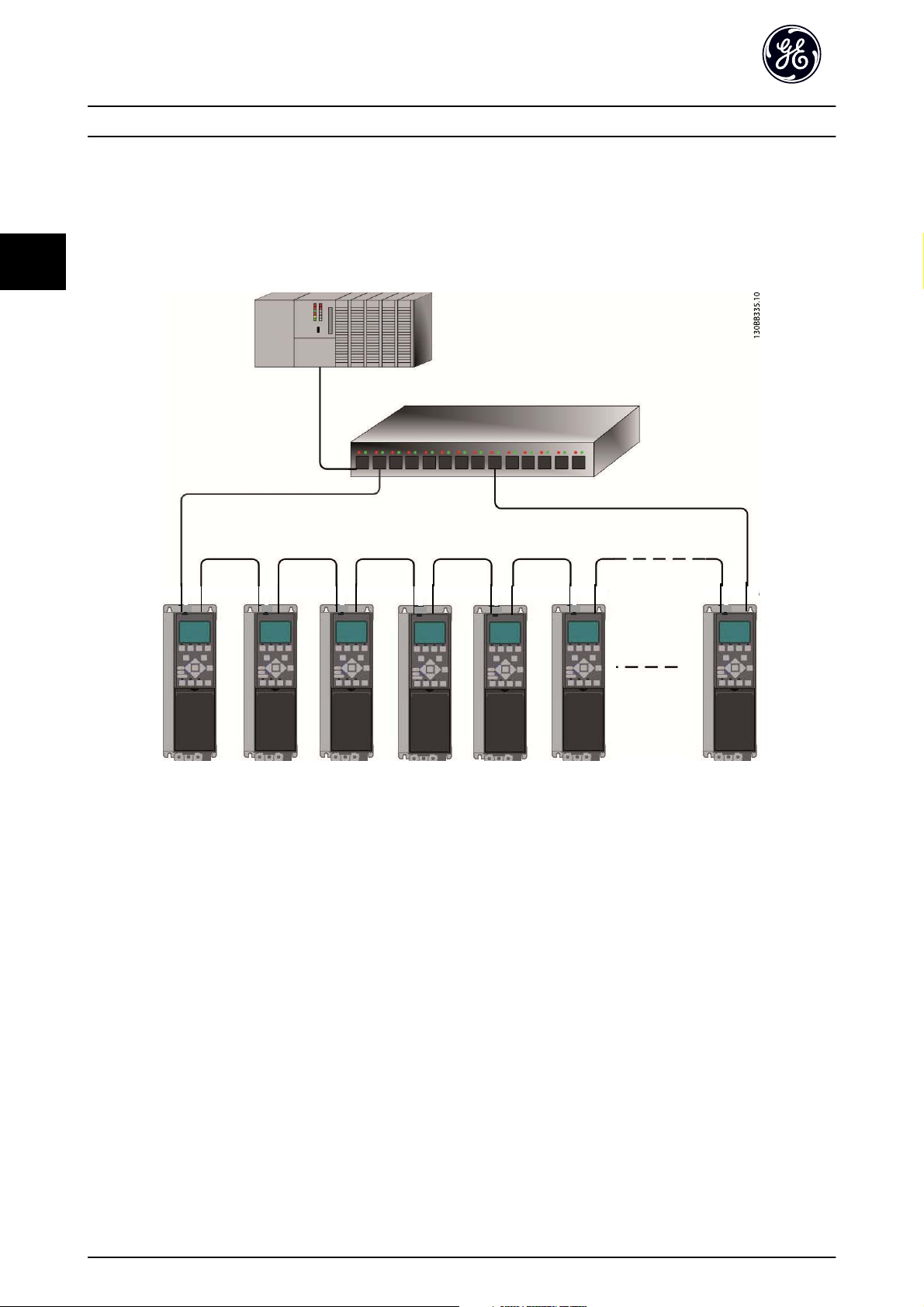
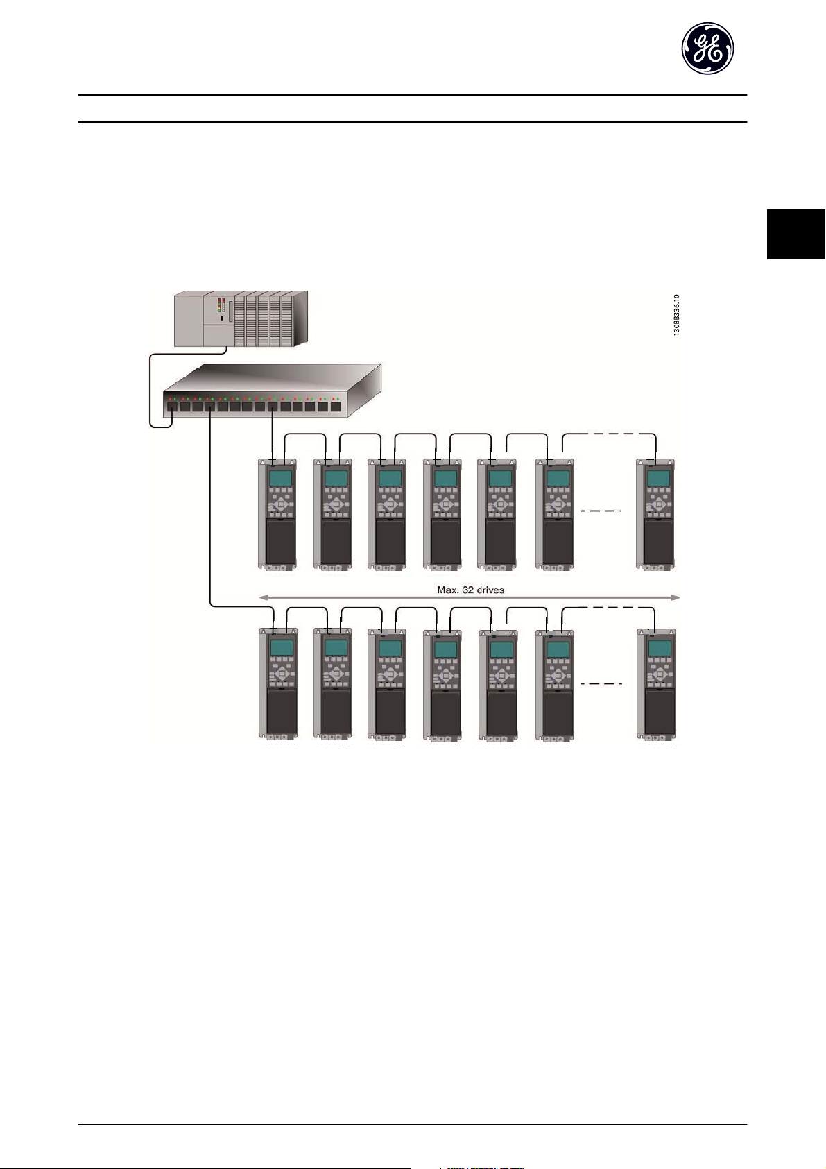
3.1.5 Topology
The PROFINET module features a built-in Ethernet-switch, thus having two Ethernet RJ-45 connectors. This enables the
possibility for connecting several PROFINET options in a line topology as an alternative to the typical star-topology.
The two ports are equal, in the sense that they are transparent for the option. If only one connector is used, both ports can
be used.
3
Illustration 3.4 Star Topology
Illustration 3.5 Line Topology
11
Page 13
3
How to Install PROFINET Operating Instruction
NOTE
In a line topology all drives must be powered, either by mains or by their 24V DC option cards, for the built-in switch to
work.
Please observe that mounting drive of different power-sizes in a line topology may result in unwanted power-off behavior,
while using controlword timeout (O-02 Control Word Source to O-06 Reset Control Word Timeout. It is recommended to
mount the drives with the longest discharge time first in the line topology.
Illustration 3.6 Ring/Redundant Line Topology
CAUTION
For this type of topology it is crucial that the network switch supports detection of loss of line topology. In some cases the
detection. The switch inside the PROFINET option does not support this, but it must be supported in the switch that
connects the ring to the controller/network Please consult the manual of the switch for more information.
12
Page 14
How to Install PROFINET Operating Instruction
3
3.1.6 Recommended Design Rules
While designing Ethernet networks special attention and caution must be taken regarding active network components.
While designing a network for line topology it is important to notice that a small delay is added with each switch in the
line.
It is not recommended to connect more than 32 drive in a line. Exceeding the recommended design rules, may result in
unstable or faulted communication.
3
Illustration 3.7
13
Page 15
How to Install PROFINET Operating Instruction
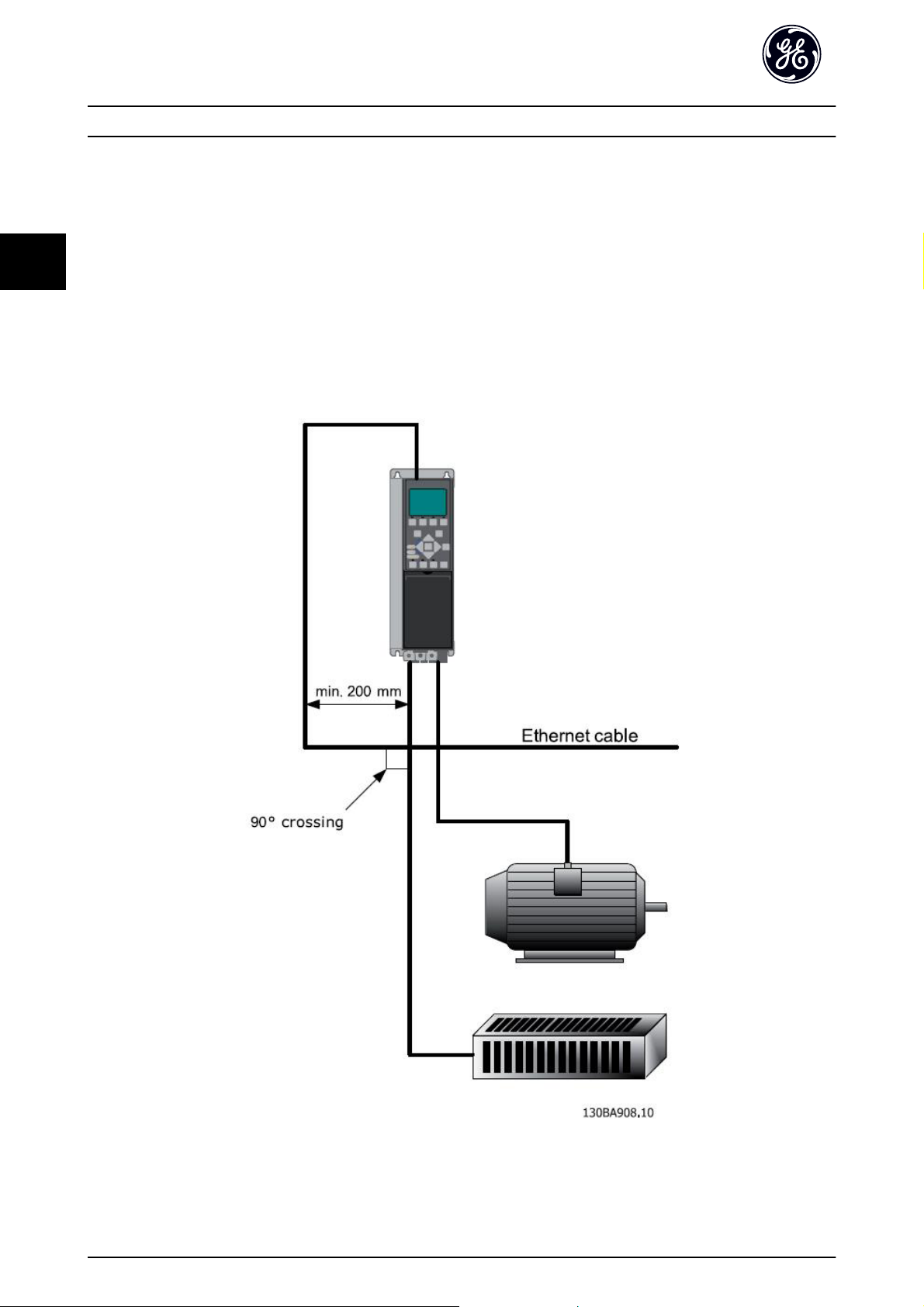
3.1.7 EMC Precautions
The following EMC precautions are recommended in order to achieve interference-free operation of the Ethernet network.
Additional EMC information is available in the AF-600 FP/AF-650 GP series Design Guide.
3
NOTE
Relevant national and local regulations, for example regarding protective earth connection, must be observed.
The Ethernet communication cable must be kept away from motor and brake resistor cables to avoid coupling of high
frequency noise from one cable to the other. Normally a distance of 200mm (8 inches) is sufficient, but maintaining the
greatest possible distance between the cables is recommended, especially where cables run in parallel over long distances.
When crossing is unavoidable, the Ethernet cable must cross motor and brake resistor cables at an angle of 90°.
Illustration 3.8
14
Page 16

How to Configure PROFINET Operating Instruction
4
4How to Configure
4.1.1 IP Settings
All IP-related parameters are located in parameter group
EN-##: The parameters are all set to PROFINET standard
values, so that only a minimum change is necessary.
EN-00 IP Address Assignment
EN-01 IP Address
EN-02 Subnet Mask
EN-03 Default Gateway
EN-04 DHCP Server
EN-05 Lease Expires
EN-06 Name Servers
EN-07 Domain Name
EN-08 Host Name
EN-09 Physical Address
The PROFINET option offers several ways of IP address
assignment.
Setting up drive with manual assigned IP address:
Parameter Value
EN-00 IP Address
Assignment
EN-01 IP Address 192.168.0.003*
EN-02 Subnet Mask 255.255.255.0*
EN-03 Default
Gateway
[0] MANUAL
optional
EN-09 Physical Address reads out the MAC address of
option, which is also printed on the label of the option. If
using fixed leases together with DHCP or BOOTP, the
physical MAC address is linked with a fixed IP address.
NOTE
If no DHCP or BOOTP reply has been received after 4
attempts (e.g. if the DHCP/BOOTP server has been
powered off), the option will fallback to the last
functioning IP address.
EN-03 Default Gateway is optional and only used in routed
networks.
EN-06 Name Servers
EN-07 Domain Name
EN-08 Host Name
are used with Domain Name Server systems and are all
optional. If DHCP or BOOTP is selected as IP address
assignment, these parameters are read only.
NOTE
It is only possible to assign valid class A, B and C IP
address to the option. The valid ranges are shown in
Table 4.3:
Class A 1.0.0.1 - 126.255.255.254
Class B 128.1.0.1 - 191.255.255.254
Class C 192.0.1.1 - 223.255.254.254
4
Table 4.1
*= Class C IP address example. Any valid IP address can be entered.
Setting up drive with automatic (BOOTP/DHCP) assigned IP
address:
Parameter Value
EN-00 IP Address
Assignment
EN-01 IP Address Read only
EN-02 Subnet Mask Read only
EN-03 Default
Gateway
Table 4.2
By IP address assigned by DHCP/BOOTP/DCP server, the
assigned IP Address and Subnet Mask can be read out in
EN-01 IP Address and EN-02 Subnet Mask. In EN-04 DHCP
Server the IP address of the found DHCP or BOOTP server
is displayed. For DHCP only: The remaining lease-time can
be read-out in EN-05 Lease Expires. If lease time is set to 0
(zero) the timer will never expire.
[0] MANUAL/[1] DHCP/[2] BOOTP/[10] DCP
Read only
Table 4.3
15
Page 17

4
How to Configure PROFINET Operating Instruction
4.1.2 Ethernet Link Parameters
Parameter group EN-1# holds information Ethernet Link
information:
EN-10 Link Status
EN-11 Link Duration
EN-12 Auto Negotiation
EN-13 Link Speed
EN-14 Link Duplex
Please note the Ethernet Link Parameters are unique per
port.
EN-10 Link Status and EN-11 Link Duration displays
information on the link status, per port.
EN-10 Link Status will display Link or No Link according to
the status of the present port.
EN-11 Link Duration will display the duration of the link on
the present port. If the link is broken the counter will be
reset.
EN-12 Auto Negotiation - is a feature that enables two
connected Ethernet devices to choose common
transmission parameters, such as speed and duplex mode.
In this process, the connected devices first share their
capabilities as for these parameters and then choose the
fastest transmission mode they both support.
Incapability between the connected devices, may lead to
decreased communication performance.
To prevent this, Auto Negotiation can be disabled.
If EN-12 Auto Negotiation is set to OFF, link speed and
duplex mode can be configured manually in EN-13 Link
Speed and EN-12 Auto Negotiation.
EN-13 Link Speed - displays/sets the link speed per port.
“None” is displayed if no link is present.
EN-14 Link Duplex - displays/sets the duplex mode per port.
Half-duplex provides communication in both directions,
but only in one direction at a time (not simultaneously).
Full-duplex allows communication in both directions, and
unlike half-duplex, allows for this to happen simultaneously.
16
Page 18

How to Configure the System PROFINET Operating Instruction
5
5 How to Configure the System
outlined below show how to add a new GSD file to the
5.1 Configure the PROFINET Network
All PROFINET devices that are connected to the same
network must have a unique device name.
The PROFINET device name of the frequency converter can
be set via:
EN-08 Host Name
5.2 Configure the Controller
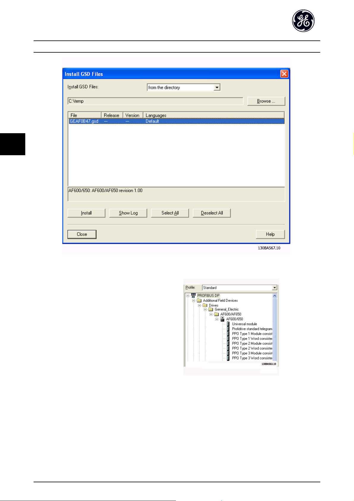
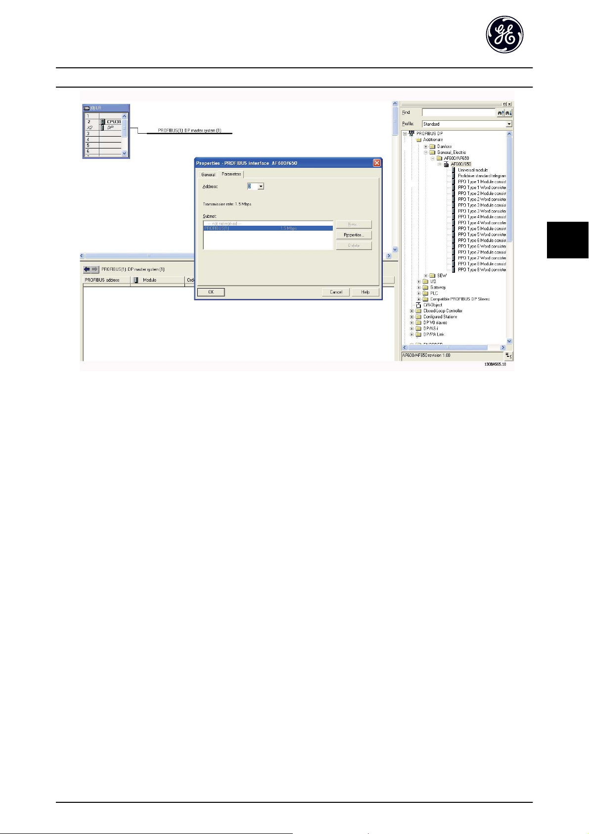
5.2.1 GSD File
In order to configure a PROFINET Controller, the configuration tool needs a GSD file for each type of slave on the
network. The GSD file is a PROFINET standard text file
containing the necessary communication setup data for a
slave. Download the GSD file for the AF-6 Series drives at
www.geelectrical.com/drives. The name of the GSD file
may vary compared to this manual. Please download the
latest version from the above website.
Simatic Manager software tool. For each drive series, a GSD
file is typically imported once only, following the initial
installation of the software tool.
Illustration 5.1
5
The first step in configuration of the PROFINET Controller is
to import the GSD file in the configuration tool. The steps
17
Page 19
5
How to Configure the System PROFINET Operating Instruction
Illustration 5.2
The GSD file is now imported and will be accessible via the
following path in the Hardware catalogue:
Illustration 5.3
Open a Project, set up the Hardware and add a PROFINET Master system. Select GE FC PN then drag and drop it onto the
PROFINET IO system.
A window for the Device name of the now appears. Type the name into the field. Note that the name must match the
name in EN-08 Host Name. If the checkmark Assign IP address via the IO controller is set, the controller will download the IP
address to the IO device that has the corresponding device name. The IP address is stored in the non volatile memory of
the .
18
Page 20
How to Configure the System PROFINET Operating Instruction
5
5
Illustration 5.4
The next step is to set up the peripheral input and output data. Data set up in the peripheral area is transmitted cyclically
via telegrams/PPO types. In the example below, a PPO type 6 is dragged and dropped to slot 1.
See the PPO types section in How to Control the Frequency Converter for more information.
19
Page 21

5
How to Configure the System PROFINET Operating Instruction
Illustration 5.5
The configuration tool automatically assigns addresses in the peripheral address area. In this example the input and output
area have the following configuration:
PPO type 6:
PCD word number 0 1 2 3
Input address 256-257 258-259 260-261 262-263
Set-up STW MAV PB-16 PCD Read Configuration.2 PB-16 PCD Read Configuration.3
Table 5.1 PCD Read (Drive to PLC)
PCD word number 0 1 2 3
Output address 256-257 258-259 260-261 262-263
Set-up CTW MRV PB-15 PCD Write Configuration.2 PB-15 PCD Write Configuration.3
Table 5.2 PCD Write (PLC to Drive)
The PCDs have to be assigned via PB-16 PCD Read Configuration for inputs and PB-15 PCD Write Configuration for outputs.
Download the configuration file to the PLC. The PROFINET system should be able to go online and it will start to exchange
data when the PLC is set to Run mode.
20
Page 22

How to Configure the System PROFINET Operating Instruction
5
5.3 Configure the Frequency Converter
5.3.1 Drive Parameters
Pay particular attention to the following parameters when
configuring the frequency converter with a PROFINET
interface.
K-40 [Hand] Button on Keypad. If the Hand button
•
on the frequency converter is activated, control of
the drive via the PROFINET interface is disabled
After an initial power up the frequency converter
•
will automatically detect whether a network
option is installed in slot A, and set O-02 Control
Word Source to [Option A]. If an option is added,
changed or removed from an already commissioned drive, it will not change O-02 Control Word
Source but enter Trip Mode, and the drive will
display an error
O-10 Control Word Profile. Choose between the GE
•
Drive Profile and the PROFIdrive profile
O-50 Coasting Select to O-56 Preset Reference
•
Select. Selection of how to gate PROFINET control
commands with digital input command of the
control module.
5
NOTE
When O-01 Control Site is set to [2] Control word only, then
the settings in O-50 Coasting Select to O-56 Preset Reference
Select will be overruled, and all act on Bus-control.
O-03 Control Word Timeout Time to O-05 End-of-
•
Timeout Function. The reaction in the event of a
network time out is set via these parameters
EN-00 IP Address Assignment
•
EN-08 Host Name
•
21
Page 23

6
How to Control the Frequenc... PROFINET Operating Instruction
6 How to Control the Frequency Converter
6.1 PPO Types
The PROFIdrive profile for frequency converters specifies a number of communication objects (Parameter Process data
Objects, PPO), which are suitable for data exchange between a process controller, such as a PLC, and frequency converters.
All PPOs are defined for cyclic data transfer, so that process data (PCD) can be transferred from the controller to the slave
and vice versa. Table 6.1 shows the PPO types available for the GE AF-650 GP & AF-600 FP drives..
PPO types 3, 4, 6, 7 and 8 are pure process data objects for applications requiring no cyclic parameter access. The PLC sends
out process control data, and the frequency converter then responds with a PPO of the same length, containing process
status data. The first two bytes of the process data area (PCD 1) comprise a fixed part present in all PPO types. The first two
words of the process data area (PCD 0 and PCD1) comprise a fixed part present in all PPO types. The following data (PCD 2
to PCD 9) are flexible for PCD write entries (PB-15 PCD Write Configuration, and for PCD read entries (PB-16 PCD Read Config-
uration. The to parameters can be parameterised with process signals from the list on PB-23 Parameters for Signals.
Select the signals for transmission from the master to the frequency converter in PB-15 PCD Write Configuration (request
from master to the frequency converter). Select the signals for transmission from the frequency converter to the master in
PB-16 PCD Read Configuration (response: Drive → master).
The choice of PPO type is made in the master configuration, and is then automatically recorded in the frequency converter.
No manual setting of PPO types in the frequency converter is required. The current PPO type can be read in PB-22 Telegram
Selection.
Selection [1] Standard telegram 1 is equivalent to PPO type 3.
PB-15 PCD
Write
Configuration +
PB-16 PCD
Read Configuration
index. no.:
Type 3:
Type 4:
Type 6:
Type 7:
Type 8:
CTW:
STW: Status word
MRV: Main reference value
MAV: Main actual value (Actual output frequency)
0123456789
[0] [1] [2] [3] [4] [5] [6] [7] [8] [9]
CTW MRV PCD PCD PCD PCD PCD PCD PCD PCD
STW MAV
Control word
PCD
Table 6.1
22
Page 24

How to Control the Frequenc... PROFINET Operating Instruction
6
6.2 Process Data
Use the process data part of the PPO for controlling and
monitoring the frequency converter via the PROFINET.
6.2.1 Process Control Data
Process data sent from the PLC to the frequency converter
are defined as Process Control Data (PCD).
Master slave
0 1 2 ...... 9
PCD write
Table 6.2
PCD 0 contains a 16-bit control word, where each bit
controls a specific function of the frequency converter, see
6.3 Control Profile. PCD 1 contains a 16-bit speed set point
in percentage format. See 6.2.3 Reference Handling .
The content of PCD 2 to PCD 9 is programmed in
PB-15 PCD Write Configuration and PB-16 PCD Read Configuration.
CTW MRV PCD ...... PCD
6.2.2 Process Status Data
6.2.3 Reference Handling
The reference handling in the GE AF-650 GP & AF-600 FP
drives is an advanced mechanism that sums up references
from different sources.
For more information on reference handling, please refer
to the AF-650 GP or AF-600 FP Design Guides.
6
Illustration 6.1
The reference, or speed set point (MRV, send via PROFINET
is always transmitted to the frequency converter in
percentage format as integers represented in hexadecimal
(0-4000 hex).
Process data sent from the frequency converter contain
information about the current state of the drive.
Slave master
0 1 2 ...... 9
STW MAV PCD ...... PCD
PCD read
Table 6.3
PCD 0 contains a 16-bit status word, where each bit
contains information regarding a possible state of the
frequency converter.
PCD 1 contains per default the value of the current speed
of the frequency converter in percentage format (see 6.2.3
Reference Handling ).
The content of PCD 2 to PCD 9 is programmed in
PB-16 PCD Read Configuration.
23
Page 25

6
How to Control the Frequenc... PROFINET Operating Instruction
Depending on the setting of F-50 Reference Range the reference and MAV are scaled accordingly:
Illustration 6.2
NOTE
If F-50 Reference Range is set to [0] Min - Max, a negative reference will be handled as 0%.
The actual output of the frequency converter is limited by the speed limit parameters in F-18 Motor Speed Low Limit [RPM]
to F-15 Motor Speed High Limit [Hz].
The final speed limit is set by F-03 Max Output Frequency 1.
The reference and the MAV have the format which appears
from the table
MRV / MAV Integer in hex Integer in decimal
100% 4000 16.384
75% 3000 12.288
50% 2000 8.192
25% 1000 4.096
0% 0 0
-25% F000 -4.096
-50% E000 -8.192
-75% D000 -12.288
-100% C000 -16.384
Table 6.4
NOTE
Negative numbers are formed as two's complement.
NOTE
The data type for MRV and MAV is a N2 16 bit
standardised value, meaning it can express a range from
-200% to +200% (8001 to 7FFF).
MRV / MAV Actual Speed
0% 0 hex 100 RPM
25% 1000 hex 825 RPM
50% 2000 hex 1550 RPM
75% 3000 hex 2275 RPM
100% 4000 hex 3000 RPM
Table 6.5
6.2.4 Process Control Operation
In process control operation H-40 Configuration Mode is set
to [3] Process.
The reference range in F-50 Reference Range is alway [0]
Min - Max.
- MRV represents the process setpoint.
- MAV expresses the actual process feedback (range +/200%).
H-40 Configuration Mode set to [0] Speed open loop.
F-50 Reference Range set to [0] Min - Max.
F-52 Minimum Reference set to 100 RPM.
F-53 Maximum Reference set to 3000 RPM.
24
Page 26

How to Control the Frequenc... PROFINET Operating Instruction
6
6.2.5 Influence of the Digital Input
Terminals upon Drive Control Mode,
O-50 Coasting Select to O-56 Preset
Reference Select
The influence of the digital input terminals upon control of
the frequency converter can be programmed in
O-50 Coasting Select to O-56 Preset Reference Select. Please
note the O-01 Control Site overrules the settings in
O-50 Coasting Select to O-56 Preset Reference Select, and
Terminal 37 Coasting Stop (safe) overrules any parameter.
Terminal 37 Safe Stop is standard on the AF-650 GP only.
Each of the digital input signals can be programmed to
logic AND, logic OR, or to have no relation to the
corresponding bit in the control word. In this way a
specific control command i.e. stop / coast, can be initiated
by network only, network AND Digital Input, or Ether
Network OR Digital input terminal.
CAUTION
In order to control the frequency converter via PROFINET,
O-50 Coasting Select must be set to either Bus [1], or to
Logic AND [2], and O-01 Control Site must be set to [0] or
[2].
6.4.1 Control Word according to PROFIdrive
Profile (CTW)
The Control word is used to send commands from a
master (e.g. a PC) to a slave.
Bit Bit = 0 Bit = 1
00 OFF 1 ON 1
01 OFF 2 ON 2
02 OFF 3 ON 3
03 Coasting No coasting
04 Quick stop Accel/Decel
05 Hold frequency output Use Accel/Decel
06 Accel/Decel stop Start
07 No function Reset
08 Jog 1 OFF Jog 1 ON
09 Jog 2 OFF Jog 2 ON
10 Data invalid Data valid
11 No function Slow down
12 No function Catch up
13 Parameter set-up Selection lsb
14 Parameter set-up Selection msb
15 No function Reverse
Table 6.6
6
More detailed information and examples of logical
relationship options are provided in 10 Troubleshooting.
6.3 Control Profile
The frequency converter can be controlled according to
the GE Drive protocol. Select the desired control profile in
O-10 Control Word Profile. The choice of profile affects the
control and status word only.
6.4 PROFIdrive Control Profile and 6.5 GE Drive Control Profile
provide a detailed description of control and status data.
6.4 PROFIdrive Control Profile
This section describes the functionality of the control word
and status word in the PROFIdrive profile. Select this
profile by setting O-10 Control Word Profile.
Explanation of the Control Bits
Bit 00, OFF 1/ON 1
Normal ramp stops using the ramp times of the actual
selected ramp.
Bit 00 = "0" leads to the stop and activation of the output
relay 1 or 2 if the output frequency is 0Hz and if [Relay
123] has been selected in E-24 Function Relay.
When bit 00 = "1", the frequency converter is in State 1:
“Switching on inhibited”.
Please refer to Illustration 6.3, at the end of this section.
Bit 01, OFF 2/ON 2
Coasting stop
When bit 01 = "0", a coasting stop and activation of the
output relay 1 or 2 occurs if the output frequency is 0Hz
and if [Relay 123] has been selected in E-24 Function Relay.
When bit 01 = "1", the frequency converter is in State 1:
“Switching on inhibited”. Please refer to Illustration 6.3, at
the end of this section.
Bit 02, OFF 3/ON 3
Quick stop using the ramp time of C-23 Quick Stop Decel
Time. When bit 02 = "0", a quick stop and activation of the
output relay 1 or 2 occurs if the output frequency is 0Hz
and if [Relay 123] has been selected in E-24 Function Relay.
When bit 02 = "1", the frequency converter is in State 1:
“Switching on inhibited”.
Please refer to Illustration 6.3, at the end of this section.
25
Page 27

How to Control the Frequenc... PROFINET Operating Instruction
6
Bit 03, Coasting/No coasting
Coasting stop Bit 03 = "0" leads to a stop. When bit 03 =
"1", the frequency converter can start if the other start
conditions are satisfied.
NOTE
The selection in O-50 Coasting Select determines how bit
03 is linked with the corresponding function of the digital
inputs.
Bit 04, Quick stop/Accel/Decel
Quick stop using the ramp time of C-23 Quick Stop Decel
Time.
When bit 04 = "0", a quick stop occurs.
When bit 04 = "1", the frequency converter can start if the
other start conditions are satisfied.
NOTE
The selection in O-51 Quick Stop Select determines how bit
04 is linked with the corresponding function of the digital
inputs.
Bit 05, Hold frequency output/Use Accel/Decel
When bit 05 = "0", the current output frequency is being
maintained even if the reference value is modified.
When bit 05 = "1", the frequency converter can perform its
regulating function again; operation occurs according to
the respective reference value.
Bit 06, Decel stop/Start
Normal ramp stop using the ramp times of the actual
ramp as selected. In addition, activation of the output relay
01 or 04 if the output frequency is 0Hz if Relay 123 has
been selected in E-24 Function Relay. Bit 06 = "0" leads to a
stop. When bit 06 = "1", the frequency converter can start
if the other start conditions are satisfied.
NOTE
The selection in O-53 Start Select determines how bit 06 is
linked with the corresponding function of the digital
inputs.
Bit 07, No function/Reset
Reset after switching off.
Acknowledges event in fault buffer.
When bit 07 = "0", no reset occurs.
When there is a slope change of bit 07 to "1", a reset
occurs after switching off.
Bit 09, Jog 2 OFF/ON
Activation of the pre-programmed speed in O-91 Bus Jog 2
Speed. JOG 2 is only possible if bit 04 = "0" and bit 00 - 03
= "1".
Bit 10, Data invalid/valid
Is used to tell the frequency converter whether the control
word is to be used or ignored. Bit 10 = “0” causes the
control word to be ignored, Bit 10 = “1” causes the control
word to be used. This function is relevant, because the
control word is always contained in the message,
regardless of which type of message is used, i.e. it is
possible to turn off the control word if you do not wish to
use it in connection with updating or reading parameters.
Bit 11, No function/Slow down
Is used to reduce the speed reference value by the amount
given in F-62 Catch up/slow Down Value value. When bit 11
= "0", no modification of the reference value occurs. When
bit 11 = "1", the reference value is reduced.
Bit 12, No function/Catch up
Is used to increase the speed reference value by the
amount given in F-62 Catch up/slow Down Value.
When bit 12 = "0", no modification of the reference value
occurs.
When bit 12 = "1", the reference value is increased.
If both slowing down and accelerating are activated (bit 11
and 12 = "1"), slowing down has priority, i.e. the speed
reference value will be reduced.
Bits 13/14, Set-up selection
Bits 13 and 14 are used to choose between the four
parameter set-ups according to Table 6.7:
The function is only possible if Multi Set-up has been
chosen in K-10 Active Set-up. The selection in O-55 Set-up
Select determines how bits 13 and 14 are linked with the
corresponding function of the digital inputs. Changing setup while running is only possible if the set-ups have been
linked in K-12 This Set-up Linked to.
Set-up Bit 13 Bit 14
100
210
301
411
Table 6.7
Bit 08, Jog 1 OFF/ON
Activation of the pre-programmed speed in O-90 Bus Jog 1
Speed. JOG 1 is only possible if bit 04 = "0" and bit 00 - 03
= "1".
26
Bit 15, No function/Reverse
Bit 15 = “0” causes no reversing.
Bit 15 = “1” causes reversing.
Note: In the factory setting reversing is set to digital in
O-54 Reversing Select.
Page 28

How to Control the Frequenc... PROFINET Operating Instruction
6
NOTE
Bit 15 causes reversing only when Ser. communication,
Logic or or Logic and is selected.
6.4.2 Status Word according to PROFIdrive
Profile (STW)
The Status word is used to notify a master (e.g. a PC)
about the status of a slave.
Bit Bit = 0 Bit = 1
00 Control not ready Control ready
01 Drive not ready Drive ready
02 Coasting Enable
03 No error Trip
04 OFF 2 ON 2
05 OFF 3 ON 3
06 Start possible Start not possible
07 No warning Warning
08
09 Local operation Bus control
10 Out of frequency limit Frequency limit ok
11 No operation In operation
12 Drive OK Stopped, autostart
13 Voltage OK Voltage exceeded
14 Torque OK Torque exceeded
15 Timer OK Timer exceeded
Table 6.8
Explanation of the Status Bits
Speed
≠
reference
Speed = reference
Bit 03, No error/Trip
When bit 03 = "0", no error condition of the frequency
converter exists.
When bit 03 = "1", the frequency converter has tripped
and requires a reset signal before it can start.
Bit 04, ON 2/OFF 2
When bit 01 of the Control word is "0", then bit 04 = "0".
When bit 01 of the Control word is "1", then bit 04 = "1".
Bit 05, ON 3/OFF 3
When bit 02 of the Control word is "0", then bit 05 = "0".
When bit 02 of the Control word is "1", then bit 05 = "1".
Bit 06, Start possible/Start not possible
If PROFIdrive has been selected in O-10 Control Word
Profile, bit 06 will be "1" after a switch-off acknowledgement, after activation of OFF2 or OFF3, and after
switching on the mains voltage. Start not possible will be
reset, with bit 00 of the Control word being set to "0" and
bit 01, 02 and 10 being set to "1".
Bit 07, No warning/Warning
Bit 07 = “0” means that there are no warnings.
Bit 07 = “1” means that a warning has occurred.
Bit 08, Speed ≠ reference / Speed = reference
When bit 08 = "0", the current speed of the motor deviates
from the set speed reference value. This may occur, for
example, when the speed is being changed during start/
stop through accel/decel.
When bit 08 = "1", the current speed of the motor
corresponds to the set speed reference value.
6
Bit 00, Control not ready/ready
When bit 00 = "0", bit 00, 01 or 02 of the Control word is
"0" (OFF 1, OFF 2 or OFF 3) - or the frequency converter is
switched off (trip).
When bit 00 = "1", the frequency converter control is
ready, but there is not necessarily power supply to the unit
present (in the event of external 24 V supply of the control
system).
Bit 01, Drive not ready/ready
Same significance as bit 00, however, there is a supply of
the power unit. The frequency converter is ready when it
receives the necessary start signals.
Bit 02, Coasting/Enable
When bit 02 = "0", bit 00, 01 or 02 of the Control word is
"0" (OFF 1, OFF 2 or OFF 3 or coasting) - or the frequency
converter is switched off (trip).
When bit 02 = "1", bit 00, 01 or 02 of the Control word is
"1"; the frequency converter has not tripped.
Bit 09, Local operation/Bus control
Bit 09 = "0" indicates that the frequency converter has
been stopped by means of the stop button on the keypad,
or that [Linked to hand] or [Local] has been selected in
F-02 Operation Method.
When bit 09 = "1", the frequency converter can be
controlled through the serial interface.
Bit 10, Out of frequency limit/Frequency limit OK
When bit 10 = "0", the output frequency is outside the
limits set in H-72 Warning Speed Low and H-73 Warning
Speed High. When bit 10 = "1", the output frequency is
within the indicated limits.
Bit 11, No operation/Operation
When bit 11 = "0", the motor does not turn.
When bit 11 = "1", the frequency converter has a start
signal, or the output frequency is higher than 0 Hz.
27
Page 29

How to Control the Frequenc... PROFINET Operating Instruction
6
Bit 12, Drive OK/Stopped, autostart
When bit 12 = "0", there is no temporary overloading of
the inverter.
When bit 12 = "1", the inverter has stopped due to
overloading. However, the frequency converter has not
switched off (trip) and will start again after the overloading
has ended.
Bit 13, Voltage OK/Voltage exceeded
When bit 13 = "0", the voltage limits of the frequency
converter are not exceeded.
When bit 13 = "1", the direct voltage in the intermediate
circuit of the frequency converter is too low or too high.
Bit 14, Torque OK/Torque exceeded
When bit 14 = "0", the motor torque is below the limit
selected in F-40 Torque Limiter (Driving) and F-41 Torque
Limiter (Braking). When bit 14 = "1", the limit selected in
F-40 Torque Limiter (Driving) or F-41 Torque Limiter (Braking)
is exceeded.
Bit 15, Timer OK/Timer exceeded
When bit 15 = "0", the timers for the thermal motor
protection and electronic overload protection have not
exceeded 100%.
When bit 15 = "1", one of the timers has exceeded 100%.
6.4.3 PROFIdrive State - Transition Diagram
In the PROFIdrive Control profile, the control bits 0 to 3 perform the basic start-up/power down functions, whereas the
control bits 4 to 15 perform application-oriented control.
Illustration 6.3 shows the basic state-transition diagram, where control bits 0 to 3 control the transitions, and the
corresponding status bit indicates the actual state. The black bullets indicate the priority of the control signals, where fewer
bullets indicate lower priority, and more bullets indicate higher priority.
Illustration 6.3 PROFIdrive State Transition Diagram
28
Page 30

How to Control the Frequenc... PROFINET Operating Instruction
6
6.5 GE Drive Control Profile
6.5.1 Control Word according to Drive
Profile (CTW)
To select GE Drive protocol in the control word,
O-10 Control Word Profile must be set to GE Drive protocol
[0]. The control word is used to send commands from a
master (PLC or PC) to a slave (frequency converter).
Please refer to 9 Application Examples for an example of a
control word message using PPO type 3.
Bit Bit value = 0 Bit value = 1
00 Reference value external selection lsb
01 Reference value external selection msb
02 DC brake Accel/Decel
03 Coasting No coasting
04 Quick stop Accel/Decel
05 Hold output frequency Use Accel/Decel
06 Accel/Decel stop Start
07 No function Reset
08 No function Jog
09 Ramp 1 Accel/Decel 2
10 Data invalid Data valid
11 No function Relay 01 active
12 No function Relay 04 active
13 Parameter set-up selection lsb
14 Parameter set-up selection msb
15 No function Reverse
Programmed
ref. value
1 C-05 Multi-step
2 C-05 Multi-step
3 C-05 Multi-step
4 C-05 Multi-step
Table 6.10
Parameter Bit 01 Bit 00
00
Frequency 1 - 8 [0]
01
Frequency 1 - 8 [1]
10
Frequency 1 - 8 [2]
11
Frequency 1 - 8 [3]
6
Table 6.9
Explanation of the Control Bits
Bits 00/01 Reference value
Bits 00 and 01 are used to choose between the four
reference values, which are pre-programmed in C-05 Multi-
step Frequency 1 - 8 according to Table 6.10:
NOTE
In O-56 Preset Reference Select a selection is made to define
how Bit 00/01 gates with the corresponding function on
the digital inputs.
29
Page 31

6
How to Control the Frequenc... PROFINET Operating Instruction
Bit 02, DC brake
Bit 02 = 0 leads to DC braking and stop. Braking current
and duration are set in B-01 DC Brake Current and B-02 DC
Braking Time. Bit 02 = 1 leads to ramping.
Bit 03, Coasting
Bit 03 = 0 causes the frequency converter to immediately
"let go" of the motor (the output transistors are "shut off"),
so that it coasts to a standstill.
Bit 03 = 1 enables the frequency converter to start the
motor if the other starting conditions have been fulfilled.
NOTE
In O-50 Coasting Select a selection is made to define how
Bit 03 gates with the corresponding function on a digital
input.
Bit 04, Quick stop
Bit 04 = 0 causes a stop, in which the motor speed is
ramped down to stop via C-23 Quick Stop Decel Time.
Bit 05, Hold output frequency
Bit 05 = 0 causes the present output frequency (in Hz) to
freeze. The frozen output frequency can then be changed
only by means of the digital inputs (E-01 Terminal 18
Digital Input to E-06 Terminal 33 Digital Input) programmed
to Speed up and Speed down.
NOTE
If Freeze output is active, the frequency converter can only
be stopped by the following:
Bit 03 Coasting stop
•
Bit 02 DC braking
•
Digital input (E-01 Terminal 18 Digital Input to
•
E-06 Terminal 33 Digital Input) programmed to DC
braking, Coasting stop or Reset and coasting stop.
Bit 06, Ramp stop/start:
Bit 06 = 0 causes a stop, in which the motor speed is
ramped down to stop via the selected ramp down
parameter.
Bit 06 = 1" permits the frequency converter to start the
motor, if the other starting conditions have been fulfilled.
NOTE
In O-53 Start Select a selection is made to define how Bit
06 Ramp stop/start gates with the corresponding function
on a digital input.
Bit 07, Reset
Bit 07 = "0" does not cause a reset. Bit 07 = "1" causes the
reset of a trip. Reset is activated on the signals leading
edge, i.e. when changing from logic "0" to logic "1".
30
Page 32

How to Control the Frequenc... PROFINET Operating Instruction
6
Bit 08, Jog
Bit 08 = "1" causes the output frequency to be determined
by C-21 Jog Speed [RPM].
Bit 09, Selection of ramp 1/2
Bit 09 = "0" means that ramp 1 is active
Bit 09 = "1" means that ramp 2 is active.
Bit 10, Data not valid/Data valid
Is used to tell the frequency converter whether the control
word is to be used or ignored. Bit 10 = "0" causes the
control word to be ignored.
Bit 10 = "1" causes the control word to be used. This
function is relevant, because the control word is always
contained in the message, regardless of which type of
message is used, i.e. it is possible to turn off the control
word if you do not wish to use it in connection with
updating or reading parameters.
Bit 11, Relay 01
Bit 11 = "0" Relay not activated.
Bit 11 = "1" Relay 01 activated, provided Control word bit
11 has been chosen in E-24 Function Relay.
6.5.2 Status Word according to GE Drive
Profile (STW)
The status word is used to inform the master (e.g. a PC) of
the operation mode of the slave (frequency converter).
Please refer to 9 Application Examples for an example of a
status word message using PPO type 3.
Explanation of the Status Bits
Bit 00, Control not ready/ready
Bit 00 = "0" means that the frequency converter has
tripped.
Bit 00 = "1" means that the frequency converter controls
are ready, but that the power component is not necessarily
receiving any power supply (in case of external 24V supply
to controls).
Bit 01, Drive ready
Bit 01 = "1". The frequency converter is ready for
operation, but there is an active coasting command via the
digital inputs or via serial communication.
6
Bit 12, Relay 04
Bit 12 = "0" Relay 04 has not been activated.
Bit 12 = "1" Relay 04 has been activated, provided Control
word bit 12 has been chosen in E-24 Function Relay.
Bit 13/14, Selection of set-up
Bits 13 and 14 are used to choose from the four menu setups according to Table 6.11:
The function is only possible when Multi-Set-ups is selected
in K-10 Active Set-up.
Set-up Bit 14 Bit 13
10 0
20 1
31 0
41 1
Table 6.11
In O-55 Set-up Select a selection is made to define how Bit
13/14 gates with the corresponding function on the digital
inputs.
Bit 15 Reverse
Bit 15 = "0" causes no reversing.
Bit 15 = "1" causes reversing.
Bit 02, Coasting stop
Bit 02 = "0". The frequency converter has released the
motor.
Bit 02 = "1". The frequency converter can start the motor
when a start command is given.
Bit Bit = 0 Bit = 1
00 Control not ready Control ready
01 Drive not ready Drive ready
02 Coasting Enable
03 No error Trip
04 No error Error (no trip)
05 Reserved -
06 No error Triplock
07 No warning Warning
08 Speed reference Speed = reference
09 Local operation Bus control
10 Out of frequency limit Frequency limit ok
11 No operation In operation
12 Drive OK Stopped, autostart
13 Voltage OK Voltage exceeded
14 Torque OK Torque exceeded
15 Timer OK Timer exceeded
Table 6.12
Bit 03, No error/trip
Bit 03 = "0" means that the frequency converter is not in
fault mode.
Bit 03 = "1" means that the frequency converter is tripped,
and that a reset signal is required to re-establish operation.
31
Page 33

How to Control the Frequenc... PROFINET Operating Instruction
6
Bit 04, No error/error (no trip)
Bit 04 = "0" means that the frequency converter is not in
fault mode.
Bit 04 = 1 means that there is a frequency converter error
but no trip.
Bit 05, Not used
Bit 05 is not used in the status word.
Bit 06, No error/triplock
Bit 06 = "0" means that the frequency converter is not in
fault mode.
Bit 06 = 1 means that the frequency converter is tripped,
and locked.
Bit 07, No warning/warning
Bit 07 = "0" means that there are no warnings.
Bit 07 = "1" means that a warning has occurred.
Bit 08, Speed reference/speed = reference
Bit 08 = "0" means that the motor is running, but that the
present speed is different from the preset speed reference.
It might, for example, be the case while the speed is being
ramped up/down during start/stop.
Bit 08 = "1" means that the present motor present speed
matches the preset speed reference.
Bit 13, Voltage OK/limit exceeded
Bit 13 = "0" means that there are no voltage warnings.
Bit 13 = "1" means that the DC voltage in the frequency
converters intermediate circuit is too low or too high.
Bit 14, Torque OK/limit exceeded
Bit 14 = "0" means that the motor current is lower than
the torque limit selected in F-40 Torque Limiter (Driving) or
F-41 Torque Limiter (Braking).
Bit 14 = "1" means that the torque limit in F-40 Torque
Limiter (Driving) and F-41 Torque Limiter (Braking) has been
exceeded.
Bit 15, Timer OK/limit exceeded
Bit 15 = "0" means that the timers for motor thermal
protection and electronic overload protection, respectively,
have not exceeded 100%.
Bit 15 = "1" means that one of the timers has exceeded
100%.
Bit 09, Local operation/bus control
Bit 09 = "0" means that [STOP/RESET] is activated on the
control unit, or that Local control in F-02 Operation Method
is selected. It is not possible to control the frequency
converter via serial communication.
Bit 09 = "1" means that it is possible to control the
frequency converter via the network/ serial communication.
Bit 10, Out of frequency limit
Bit 10 = "0", if the output frequency has reached the value
in F-18 Motor Speed Low Limit [RPM] or F-17 Motor Speed
High Limit [RPM].
Bit 10 = "1" means that the output frequency is within the
defined limits.
Bit 11, No operation/in operation
Bit 11 = "0" means that the motor is not running.
Bit 11 = "1" means that the frequency converter has a start
signal or that the output frequency is greater than 0Hz.
Bit 12, Drive OK/stopped, autostart
Bit 12 = "0" means that there is no temporary over
temperature on the inverter.
Bit 12 = "1" means that the inverter has stopped because
of over temperature, but that the unit has not tripped and
will resume operation once the over temperature stops.
32
Page 34

PROFINET Acyclic Communicat... PROFINET Operating Instruction
7
7 PROFINET Acyclic Communication
PROFINET offers additional to the cyclical data communication, an cyclical communication. This feature is possible
by an IO controller (e.g. PLC), as well as an IO Supervisor
(e.g. PC Tool).
Cyclical communication means that data transfer takes
place all the time with a certain update rate. This is the
known function normally used for quick update of I/O
Process Data. A-cyclical communication means a one time
event, mainly used for Read/Write on parameters from
Process controllers, PC based tools or monitoring systems.
7.1.1 Features of an IO Controller System
- Cyclical data exchange.
- A-cyclical read/write on parameters.
The a-cyclical connection is fixed and can not be changed
during operation.
In general an IO controller is used as Process controller,
responsible for commands, speed reference, status of the
application etc. ( PLC or PC based controller.)
The IO controller, a-cyclical connection might be used for
general parameter access in the slaves.
7.1.2 Features of an IO-Supervisor System
- Initiate/Abort a-cyclical connection.
- A-cyclical read/write on parameters.
The a-cyclical connection can be established dynamically
(Initiate) or removed (Abort) even though an IO controller
is active on the network.
7
The a-cyclical connection is typically used for configuration
or commissioning tools for easy access to each parameter
in any slave in the system.
33
Page 35

7
PROFINET Acyclic Communicat... PROFINET Operating Instruction
7.1.3 Addressing Scheme
The structure of a PROFINET IO Device is shown in Illustration 7.1.
An IO device consists of a number of physical or virtual slots. Slot 0 is always present, and represents the basic unit. Each
slot contains a number of data blocks addressed by an index.
The master must address a variable in the slave as follows: /Slave address/Slot #/Index #
Illustration 7.1 PROFINET IO Device Structure
34
Page 36

PROFINET Acyclic Communicat... PROFINET Operating Instruction
7
7.1.4 Acyclic Read/Write Request Sequence
A Read or Write service on a drive parameter will take place as illustrated in Illustration 7.2.
7
Illustration 7.2 Acyclic Read/Write Request Sequence
A Read or Write on a drive parameter must be initiated by an acyclic write service on slot 0, index 47. If this Write request is
valid, a positive write response without data is returned from the drive immediately. If not, a negative write response is
returned from the drive.
The drive will now interpret the “Profidrive parameter channel” part of the Data Unit, and start to perform this command
internal in the drive.
As the next step, the master will send a Read request. If the drive is still busy performing the internal parameter request, a
negative response without data is returned from the drive. This request will be repeated by the master, until the drive has
the response data ready for the drive parameter request.
The following example shows the details of the telegrams needed for the Read/Write service.
35
Page 37

PROFINET Acyclic Communicat... PROFINET Operating Instruction
7
7.1.5 Data Structure in the Acyclic
Telegrams
The data structure for a write/read parameter request,
consists of three main blocks:
Header block
Parameter block
Data block
They have to be arranged as in Table 7.1:
Word number
1 Header Request # Request ID
2 Header Axis # Param.
3 (Param. 1) Attribute # elements
4 (Param. 1) Parameter number
5 (Param. 1) Subindex number
6 (Param. 2) Attribute # elements
7 (Param. 2) Parameter number
8 (Param. 2) Subindex number
9 (Param. 3) Attribute # elements
10 (Param. 3) Parameter number
11 (Param. 3) Subindex number
....
N (Data Param. 1) Format # elements
N+1 (Data Param. 1) Data Data
N (Data Param. 2) Format # elements
N+1 (Data Param. 2) Data Data
N (Data Param. 3) Format # elements
N+1 (Data Param. 3) Data Data
N+1 (Data Param. 3) Data Data
N+1 (Data Param. 3) Data Data
Table 7.1 Request Telegram
7.1.6 Header
Request number:
Request # is used by the Master to handle the response
from the IO device. The IO device mirrors this number in
its response.
Request ID:
1 = request parameter 2 = change parameter
Axis:
Always leave this to 0 (zero). Only used in multi axis
system.
Number of parameters:
Number of parameters to read or write.
7.1.7 Parameter Block
The following 5 values have to be provided for each
parameter to read.
Attribute:
Attribute to be read
10 = Value
20 = Description
30 = Text
Number of elements:
The number of elements to read, if parameter is indexed.
Attribute:
Attribute to be read.
Parameter number:
The number of the parameter to read.
Subindex:
Pointer to the index.
7.1.8 Data Block
The Datablock is only needed for write commands. For
each parameter to write this information has to be setup.
Format:
The format of the information to write,
2: Integer 8
3: Integer 16
4: Integer 32
5: Unsigned 8
6: Unsigned 16
7: Unsigned 32
9: Visible string
33: Normalized value 2 bytes
35: Bit sequence of 16 Boolean variables
54: Time difference without date
For the individual drive series, the programming guide
contains a table with parameter number, format and other
relevant information and will not be further explained in
this document.
Number of elements:
The number of elements to read if parameter is indexed.
36
Page 38

PROFINET Acyclic Communicat... PROFINET Operating Instruction
7
Data:
The actual value to transfer. The amount of data has to be
exactly the size requested in the parameter block. If the
size differs, the request will generate an error.
On a successful transmission of a request command, the
master can read the response from the drive. The response
does look very much like the request command. The
response only consists of two blocks, the header and the
data block.
1 Header Request # Request ID
2 Header Axis # Param.
3 (Data Param. 1) Format Error code
4 (Data Param. 1) Data Data
5 (Data Param. 2) Format Error code
6 (Data Param. 2) Data Data
7 (Data Param. 3) Format Error code
8 (Data Param. 3) Data Data
9 (Data Param. 3) Data Data
10 (Data Param. 3) Data Data
Table 7.2 Response Telegram
7.1.9 Header
Request number:
Request # is used by the Master to handle the response
from the IO device. The IO device does mirror this number
in its response.
Request ID:
1 = request parameter
2 = change parameter
Axis:
Always leave this to 0 (zero).
Only used in multi axis system.
Number of parameters:
Number of parameters transferred.
7.1.10 Data Block
The Datablock is only needed for write commands. For
each parameter to write, This information has to be setup.
Format:
See under the request telegram.
Error code:
If the IO device does discover an error during the
execution of the command, it will set the error code to the
following values:
0x00 unknown parameter
0x01 parameter is read-only
0x02 value out of range due to max/min value
0x03 wrong subindex
0x04 parameter is no array
0x05 wrong datatype (wrong data length)
0x06 it is not allowed to set this parameter (only reset)
0x07 descriptive element is read-only
0x09 no description available (only value)
0x0b process control not possible
0x0f no text array available (only value)
0x11 not possible in current state
0x14 value out of range due to drive state/configuration
0x15 reply too long (more than 240 bytes)
0x16 wrong parameter address (unknown or unsupported
value for attribute, element, parameter number or
subindex or illegal combination
0x17 illegal format (for writing)
0x18 value amount not consistent
0x65 wrong axis : action not possible with this axis
0x66 unknown service request
0x67 this service is not possible with multi parameter
access
0x68 parameter value can not be read from bus
Note: all values if Hex numbers
Data:
The actual value to transfer. The amount of data has to be
exactly the size requested in the parameter block. If the
size differs, the request will generate an error.
7
37
Page 39

Parameters PROFINET Operating Instruction
8Parameters
8.1 Parameter Group O-## Communication and Option
8
O-01 Control Site
Option: Function:
The setting in this parameter overrides
the settings in O-50 Coasting Select to
O-56 Preset Reference Select.
*
Digital and
[0]
ctrl.word
[1] Digital only Control by using digital inputs only.
[2] Controlword only Control by using control word only.
Control by using both digital input and
control word.
O-03 Control Word Timeout Time
Range: Function:
1.0 s* [0.1 -
18000.0 s]
Enter the maximum time expected to pass
between the reception of two consecutive
messages. If this time is exceeded, it
indicates that the serial communication has
stopped. The function selected in
O-04 Control Word Timeout Function will
then be carried out. The time-out counter is
triggered by a valid control word.
O-04 Control Word Timeout Function
Select the time-out function. The time-out function activates
when the control word fails to be updated within the time
period specified in O-03 Control Word Timeout Time.
Option: Function:
[0] *Off Resumes control via serial bus (network or
standard) using the most recent control
word.
[1] Freeze output Freezes output frequency until communi-
cation resumes.
[2] Stop Stops with auto restart when communi-
cation resumes.
[3] Jogging Runs the motor at JOG frequency until
communication resumes.
[4] Max. speed Runs the motor at maximum frequency
until communication resumes.
[5] Stop and trip Stops the motor, then resets the drive in
order to restart: via the network, via the
reset button on the keypad or via a digital
input.
[7] Select setup 1 Changes the set-up upon reestablishment of
communication following a control word
time-out. If communication resumes causing
the time-out situation to disappear,
O-05 End-of-Timeout Function defines
whether to resume the set-up used before
O-04 Control Word Timeout Function
Select the time-out function. The time-out function activates
when the control word fails to be updated within the time
period specified in O-03 Control Word Timeout Time.
Option: Function:
the time-out or to retain the set-up
endorsed by the time-out function.
[8] Select setup 2 See [7] Select setup 1
[9] Select setup 3 See [7] Select setup 1
[10] Select setup 4 See [7] Select setup 1
[26] Trip
NOTE
The following configuration is required in order to change
the set-up after a time-out:
Set K-10 Active Set-up to [9] Multi set-up and select the
relevant link in K-12 This Set-up Linked to.
O-05 End-of-Timeout Function
Option: Function:
Select the action after receiving a valid
control word following a time-out. This
parameter is active only when O-04 Control
Word Timeout Function is set to [Set-up 1-4].
[0] Hold set-up Retains the set-up selected in O-04 Control
Word Timeout Function and displays a
warning, until O-06 Reset Control Word
Timeout toggles. Then the drive resumes its
original set-up.
*
Resume set-upResumes the set-up active prior to the time-
[1]
out.
O-06 Reset Control Word Timeout
This parameter is active only when Hold set-up [0] has been
selected in O-05 End-of-Timeout Function.
Option: Function:
[0] *Do not reset Retains the set-up specified in O-04 Control
Word Timeout Function, following a control
word time-out.
[1] Do reset Returns the drive to the original set-up
following a control word time-out. The drive
performs the reset and then immediately
reverts to the Do not reset [0] setting
38
Page 40

Parameters PROFINET Operating Instruction
8
O-10 Control Word Profile
Select the interpretation of the control and status words
corresponding to the installed network. Only the selections valid
for the network installed in slot A will be visible in the keypad
display.
Option: Function:
[0]
*
[1] PROFIdrive profile
[5] ODVA
Drive Profile
O-13 Configurable Status Word STW
Option: Function:
This parameter enables configuration of bits
12 – 15 in the status word.
[0] No function
*
Profile Default Function corresponds to the profile default
[1]
selected in O-10 Control Word Profile.
O-50 Coasting Select
Option: Function:
Select control of the coasting function via the
terminals (digital input) and/or via the network.
[0] Digit
Input
[1] Bus Activates Coast command via the serial
[2] Logic
AND
*
Logic OR Activates Coast command via the network/serial
[3]
Activates Coast command via a digital input.
communication port or network option module.
Activates Coast command via the network/serial
communication port, AND additionally via one
of the digital inputs.
communication port OR via one of the digital
inputs.
O-51 Quick Stop Select
Select control of the Quick Stop function via the terminals
(digital input) and/or via the network.
Option: Function:
[0] Digital Input
[1] Bus
[2] Logic AND
[3]
*
Logic OR
O-52 DC Brake Select
Option: Function:
Select control of the DC brake via the terminals
(digital input) and/or via the network.
[0] Digit
Input
[1] Bus ActivatesDC Brake command via the serial
[2] Logic
AND
ActivatesDC Brake command via a digital input.
communication port or network option module.
ActivatesDC Brake command via the network/
serial communication port, AND additionally via
one of the digital inputs.
O-52 DC Brake Select
Option: Function:
[3] *Logic OR ActivatesDC Brake command via the network/
serial communication port OR via one of the
digital inputs.
O-53 Start Select
Option: Function:
Select control of the drive start function via the
terminals (digital input) and/or via the network.
[0] Digit
Input
[1] Bus Activates Start command via the serial
[2] Logic
AND
*
Logic OR Activates Start command via the network/serial
[3]
Activates Start command via a digital input.
communication port or network option module.
Activates Start command via the network/serial
communication port, AND additionally via one
of the digital inputs.
communication port OR via one of the digital
inputs.
O-54 Reversing Select
Option: Function:
[0] Digital
Input
[1] Bus Activates the Reverse command via the serial
[2] Logic AND Activates the Reverse command via the
*
Logic OR Activates the Reverse command via the
[3]
Select control of the drive reverse function via
the terminals (digital input) and/or via the
network.
communication port or network option
module.
network/serial communication port, AND
additionally via one of the digital inputs.
network/serial communication port OR via one
of the digital inputs.
O-55 Set-up Select
Option: Function:
Select control of the drive set-up selection via
the terminals (digital input) and/or via the
network.
[0] Digit
Input
[1] Bus Activates the set-up selection via the serial
[2] Logic
AND
*
Logic OR Activate the set-up selection via the network/
[3]
Activates the set-up selection via a digital input.
communication port or network option module.
Activates the set-up selection via the network/
serial communication port, AND additionally via
one of the digital inputs.
serial communication port OR via one of the
digital inputs.
8
39
Page 41

Parameters PROFINET Operating Instruction
8
O-90 Bus Jog 1 Speed
Range: Function:
100 RPM* [0 - par. F-17
RPM]
Enter the jog speed. This is a fixed
jog speed activated via the serial
port or network option.
O-91 Bus Jog 2 Speed
Range: Function:
200 RPM* [0 - par. F-17
RPM]
Enter the jog speed. This is a fixed
jog speed activated via the serial
port or network option.
8.2 Parameter Group PB-## PROFIdrive
PB-15 PCD Write Configuration
Array [10]
Option: Function:
Select the parameters to be assigned to PCD 3 to 10 of
the messages. The number of available PCDs depends
on the telegram type. The values in PCD 3 to 10 will
then be written to the selected parameters as data
values. Alternatively, specify a standard Profibus
message in PB-22 Telegram Selection.
PB-16 PCD Read Configuration
Array [10]
Option: Function:
Select the parameters to be assigned to PCD 3 to 10 of
the messages. The number of available PCDs depends
on the telegram type. PCDs 3 to 10 contain the actual
data values of the selected parameters. For standard
Profibus message, see PB-22 Telegram Selection.
PB-22 Telegram Selection
Option: Function:
Select a standard Profibus telegram
configuration for the frequency
converter, as an alternative to
using the freely configurable
telegrams in PB-15 PCD Write
Configuration and PB-16 PCD Read
Configuration.
[1] Standard telegram 1
[100] None
[101] PPO 1
[102] PPO 2
[103] PPO 3
[104] PPO 4
[105] PPO 5
[106] PPO 6
[107] PPO 7
*
PPO 8
[108]
[200] Custom telegram 1
[202] Custom telegram 3
PB-23 Parameters for Signals
Array [1000]
Option: Function:
This parameter contains a list of signals available for
selection in PB-15 PCD Write Configuration and
PB-16 PCD Read Configuration.
PB-27 Parameter Edit
Option: Function:
Parameters can be edited via PROFINET, the
standard RS485 interface, or the keypad.
[0] Disabled Disables editing via PROFINET.
*
Enabled Enables editing via PROFINET.
[1]
PB-28 Process Control
Option: Function:
Process control (setting of Control Word, speed
reference, and process data) is possible via
either PROFINET or standard Network but not
both simultaneously. Local control is always
possible via the keypad. Control via process
control is possible via either terminals or
Network depending on the settings in
O-50 Coasting Select to O-56 Preset Reference
Select.
[0] Disable Disables process control via PROFINET, and
enables process control via standard Network or
PROFINET IO-Supervisor.
*
[1]
Enable
cyclic
master
Enables process control via IO Controller, and
disables process control via standard Network or
PROFINET IO-Supervisor..
PB-53 Profibus Warning Word
Range: Function:
0 N/A* [0 - 65535 N/A] This parameter displays PROFINET
communication warnings. Please refer
to the PROFINET Operating Instructions
for further information.
Read only
40
Page 42

Parameters PROFINET Operating Instruction
8
Bit Condition when bit is active
0 Connection with IO Controller is not ok
1 Reserved for status of connection with second IO
Controller
2Not used
3 Clear data command received
4Actual value is not updated
5 No Link on both port
6Not used
7 Initializing of PROFINET is not ok
8 Drive is tripped
9 Internal CAN error
10 Wrong configuration data from IO Controller
11 Not used
12 Internal error occurred
13 Not configured
14 Timeout active
15 Warning 34 active
Table 8.1
PB-65 Profile Number
Range: Function:
0 N/A* [0 - 0 N/A] This parameter contains the profile identifi-
cation. Byte 1 contains the profile number
and byte 2 the version number of the
profile.
NOTE
This parameter is not visible via keypad.
PB-71 Profibus Save Data Values
Option: Function:
EEPROM non-volatile memory, so changed
parameter values will be retained at power-
down.
*
Off Deactivates the non-volatile storage function.
[0]
[1] Store all
setups
[2] Store all
setups
Stores all parameter values for all set-ups in the
non-volatile memory. The selection returns to
Off [0] when all parameter values have been
stored.
Stores all parameter values for all set-ups in the
non-volatile memory. The selection returns to
Off [0] when all parameter values have been
stored.
PB-72 ProfibusDriveReset
Option: Function:
[0] *No action
[1] Power-on reset Resets frequency converter upon power-
up, as for power-cycle.
[2] Power-on reset
prep
[3] Comm option
reset
Resets the PROFINET option only, the
PROFINET option will go through a
power-up sequence.
When reset, the frequency converter
disappears from the Network, which may
cause a communication error from the
master.
8
PB-70 Edit Set-up
Option: Function:
Select the set-up to be edited.
[0] Factory setup Uses default data. This option can be used
as a data source to return the other set-ups
to a known state.
[1] Set-up 1 Edits Set-up 1.
[2] Set-up 2 Edits Set-up 2.
[3] Set-up 3 Edits Set-up 3.
[4] Set-up 4 Edits Set-up 4.
*
Active Set-up Follows the active set-up selected in
[9]
K-10 Active Set-up.
This parameter is unique to keypad and fieldbuses. See
also K-11 Edit Set-up.
PB-71 Profibus Save Data Values
Option: Function:
Parameter values changed via PROFINET are
not automatically stored in non-volatile
memory. Use this parameter to activate a
function that stores parameter values in the
PB-80 Defined Parameters (1)
Array [116]
No keypad access
Read only
Range: Function:
0 N/A* [0 - 9999 N/A] This parameter displays a list of all the
defined frequency converter parameters
available for PROFINET.
PB-81 Defined Parameters (2)
Array [116]
No keypad access
Read only
Range: Function:
0 N/A* [0 - 9999 N/A] This parameter displays a list of all the
defined frequency converter parameters
available for PROFINET.
41
Page 43

Parameters PROFINET Operating Instruction
8
PB-82 Defined Parameters (3)
Array [116]
No keypad access
Read only
Range: Function:
0 N/A* [0 - 9999 N/A] This parameter displays a list of all the
defined frequency converter parameters
available for PROFINET.
PB-83 Defined Parameters (4)
Array [116]
No keypad access
Read only
Range: Function:
0 N/A* [0 - 9999 N/A] This parameter displays a list of all the
defined frequency converter parameters
available for PROFINET.
PB-84 Defined Parameters (5)
Array [115]
No keypad access
Read only
Range: Function:
0 * [0 - 9999 ] This parameter displays a list of all the defined
frequency converter parameters available for
PROFINET.
PB-90 Changed Parameters (1)
Array [116]
No keypad access
Read only
Range: Function:
0 N/A* [0 - 9999 N/A] This parameter displays a list of all the
drive parameters deviating from default
setting.
PB-91 Changed Parameters (2)
Array [116]
No keypad access
Read only
Range: Function:
0 N/A* [0 - 9999 N/A] This parameter displays a list of all the
drive parameters deviating from default
setting.
PB-92 Changed Parameters (3)
Array [116]
No keypad access
Read only
Range: Function:
0 N/A* [0 - 9999 N/A] This parameter displays a list of all the
drive parameters deviating from default
setting.
PB-94 Changed Parameters (5)
Array [116]
No keypad Address
Read only
Range: Function:
0 N/A* [0 - 9999 N/A] This parameter displays a list of all the
drive parameters deviating from default
setting.
8.3 Parameter Group EN-## Ethernet
EN-00 IP Address Assignment
Option: Function:
Selects the IP Address assignment method.
*
MANUAL IP-address can be set in EN-01 IP Address IP
[0]
Address.
[1] DHCP IP-address is assigned via DHCP server.
[2] BOOTP IP-address is assigned via BOOTP server.
*
DCP DCP Assigned vis the DCP protocol.
[10]
EN-01 IP Address
Range: Function:
0 N/A* [0 - 2147483647
N/A]
EN-02 Subnet Mask
Range: Function:
0 * [0 - 2147483647 ] Configure the IP subnet mask of the
EN-03 Default Gateway
Range: Function:
0
[0 - 2147483647
N/A
N/A]
*
EN-04 DHCP Server
Range: Function:
0 N/A* [0 - 2147483647 N/A] Read only. Displays the IP
EN-05 Lease Expires
Range: Function:
0 N/A* [0 - 0 N/A] Read only. Displays the lease-time left for
the current DHCP-assigned IP address.
Configure the IP address of the
option. Read-only if EN-00 IP
Address Assignment set to DHCP
or BOOTP.
option. Read-only if EN-00 IP Address
Assignment set to DHCP or BOOTP.
Configure the IP default gateway of
the option. Read-only if EN-00 IP
Address Assignment set to DHCP or
BOOTP. In a non routed network this
adress is set to the IP adress of the IO
Device
address of the found DHCP or
BOOTP server.
42
Page 44

Parameters PROFINET Operating Instruction
8
EN-06 Name Servers
Range: Function:
0 N/A* [0 - 2147483647 N/A] IP addresses of Domain Name
Servers. Can be automatically
assigned when using DHCP.
EN-07 Domain Name
Range: Function:
0 N/A [0 - 2147483647 N/A] Domain name of the attached
network. Can be automatically
assigned when using DHCP.
EN-08 Host Name
Range: Function:
0 N/A [0 - 0 N/A] Logical (given) name of option.
NOTE
Please note that the display of the drive will only show the
first 19 characters, but the remaining characters are stored
in the drive.
EN-09 Physical Address
Range: Function:
0 N/A* [0 - 0 N/A] Read only Displays the Physical (MAC)
address of the option.
EN-1# Ethernet Link parameters
Option: Function:
Applies for whole parameter group.
[0] Port 1
[1] Port 2
EN-10 Link Status
Option: Function:
Read only. Displays the link status of the Ethernet
ports.
*
No Link
[0]
[1] Link
EN-11 Link Duration
Range: Function:
0 N/A* [0 - 0 N/A] Read only. Displays the duration of the
present link on each port in dd:hh:mm:ss.
EN-12 Auto Negotiation
Option: Function:
Configures Auto Negotiation of Ethernet link
parameters, for each port: ON or OFF.
[0] Off Link Speed and Link Duplex can be configured in
EN-13 Link Speed and EN-14 Link Duplex.
*
On
[1]
NOTE
It is recommended to set EN-12 Auto Negotiation to OFF [0]
for the PROFINET option and for the connected port. This
will ensure that the connected ports will be set to an
optimized Link Speed with Link Duplex setting. If only one
of the ports in a link is set to Auto Negotiation ON, it can
course the ports to switch to half duplex, resulting in poor
network performance. Most switches today have Auto
negotiation set, but this can lead to a longer time to
establish a connection.
EN-13 Link Speed
Option: Function:
Forces the link speed for each port in 10 or 100
Mbps. If EN-12 Auto Negotiation is set to: ON,
this parameter is read only and displays the
actual link speed. “None” is displayed if no link
is present.
*
None
[0]
[1] 10 Mbps
*
100 Mbps
[2]
EN-14 Link Duplex
Option: Function:
Forces the duplex for each port to Full or Half
duplex. If EN-12 Auto Negotiation is set to: ON,
this parameter is read only.
[0] Half Duplex
*
Full Duplex
[1]
EN-80 FTP Server
Option: Function:
[0] *Disabled Disables the built-in FTP server.
[1] Enabled Enables the built-in FTP server.
EN-81 HTTP Server
Option: Function:
[0] *Disabled Disables the built-in HTTP (web) server.
[1] Enabled Enables the built-in HTTP (web) server.
EN-82 SMTP Service
Option: Function:
[0] *Disabled Disables the SMTP (e-mail) service on the option.
[1] Enabled Enables the SMTP (e-mail) service on the option.
EN-89 Transparent Socket Channel Port
Range: Function:
4000
N/A
*
[0 - 65535
N/A]
Configures the TCP port number for
the transparent socket channel. This
enables Drive messages to be sent
transparently on Ethernet via TCP.
Default value is 4000, 0 means
8
43
Page 45

Parameters PROFINET Operating Instruction
8
EN-89 Transparent Socket Channel Port
Range: Function:
disabled. This port is used by the
DCT-10.
EN-90 Cable Diagnostic
Option: Function:
Enables/disables advanced Cable diagnosis
function. If enabled, the distance to cable errors
can be read out in EN-93 Cable Error Length. The
parameter resumes to the default setting of
Disable after the diagnostics have finished.
*
Disabled
[0]
[1] Enabled
NOTE
The cable diagnostics function will only be issued on ports
where there is no link (see EN-10 Link Status, Link Status)
EN-91 MDI-X
Option: Function:
[0] Disabled Disables the auto cross-over function.
*
Enabled Enables the auto cross-over function.
[1]
EN-92 IGMP Snooping
Option: Function:
This prevents flooding of the Ethernet protocol
stack by only forwarding multicast packets to
ports that are member of the multicast group. In
PROFINET this function is disabled.
[0] Disabled Disables the IGMP snooping function.
*
Enabled Enables the IGMP snooping function.
[1]
EN-93 Cable Error Length
Range: Function:
0
[0 -
N/A
65535
*
N/A]
EN-94 Broadcast Storm Protection
Range: Function:
-1
[-1 -
%
20 %]
*
If Cable Diagnostics is enabled in EN-90 Cable
Diagnostic, the built-in switch is possible via
Time Domain Reflectometry (TDR). This is a
measurement technique which detects
common cabling problems such as open
circuits, short circuits and impedance
mismatches or breaks in transmission cables.
The distance from the option to the error is
displayed in metres with an accuracy of +/-
2m. The value 0 means no errors detected.
The built-in switch is capable of protecting the
switch system from receiving too many broadcast
packages, which can use up network resources.
EN-94 Broadcast Storm Protection
Range: Function:
The value indicates a percentage of the total
bandwidth that is allowed for broadcast messages.
Example:
The “OFF” means that the filter is disabled - all
broadcast messages will be passed through. The
value “0%” means that no broadcast messages will
be passed through. A value of “10%” means that
10% of the total bandwidth is allowed for
broadcast messages, if the amount of broadcast
messages increases above the 10% threshold, they
will be blocked.
EN-95 Broadcast Storm Filter
Option: Function:
Applies to EN-94 Broadcast Storm
Protection; if the Broadcast Storm
Protection should also include
Multicast messages.
*
Broadcast only
[0]
[1] Broadcast &
Multicast
EN-96 Port Mirroring
Enables/disables port-mirroring function. For troubleshooting
with a network analyzer tool.
Option: Function:
[0]
*
Disable No port-mirroring
[1] Port 1 to Port 2 All network traffic on port 1 will
be mirrored to port 2.
[2] Port 2 to Port 1 All network traffic on port 2 will
be mirrored to port 1.
[254] Int. Port to Port 1
[255] Int. Port to Port 2
EN-98 Interface Counters
Range: Function:
4000 N/A* [0 - 65535
N/A]
Read only. Advanced Interface
counters, from built-in switch, can be
used for low-level trouble-shooting,
The parameter shows a sum of port 1
+ port 2.
EN-99 Media Counters
Range: Function:
0 N/A* [0 - 65535
N/A]
Read only. Advanced Interface counters,
from built-in switch, can be used for
low-level trouble-shooting, The
parameter shows a sum of port 1 + port
2.
44
Page 46

Parameters PROFINET Operating Instruction
8
8.4 PROFINET-specific Parameter List
Parameter Default value Range Conver-
Data type
sion index
O-01 Control Site Dig. & ctrl. word [0] [0 - 2] - Uint8
O-02 Control Word Source Drive RS485 [0] [0 - 4] - Uint8
O-03 Control Word Timeout Time 1 0.1-18000 -1 Uint32
O-04 Control Word Timeout Function Off [0] [0 - 10] - Uint8
O-05 End-of-Timeout Function Hold set-up [0] [0 - 1] - Uint8
O-06 Reset Control Word Timeout Do not reset [0] [0 - 1] - Uint8
O-07 Diagnosis Trigger Disable [0] [0 - 3] - Uint8
O-10 Control Word Profile GE Drive profile [0] [0 - x] - Uint8
O-13 Configurable Status Word STW
O-50 Coasting Select *Logic OR [3] [0 - 3] - Uint8
O-51 Quick Stop Select *Logic OR [3] [0 - 3] - Uint8
O-52 DC Brake Select *Logic OR [3] [0 - 3] - Uint8
O-53 Start Select *Logic OR [3] [0 - 3] - Uint8
O-54 Reversing Select *Logic OR [3] [0 - 3] - Uint8
O-55 Set-up Select *Logic OR [3] [0 - 3] - Uint8
O-56 Preset Reference Select *Logic OR [3] [0 - 3] - Uint8
0 - F-17 Motor Speed High
O-90 Bus Jog 1 Speed 100 rpm
O-91 Bus Jog 2 Speed 200 rpm
PB-15 PCD Write Configuration -- -Uint16
PB-16 PCD Read Configuration -- -Uint16
PB-22 Telegram Selection - [0 - 108] - Uint8
PB-23 Parameters for Signals -0 - 573-Uint16
PB-27 Parameter Edit Enabled [1] [0 - 1] - Uint16
PB-28 Process Control Enable cyclic master [1] [0 - 1] - Uint16
PB-44 Fault Message Counter 0[0 - 8]0Uint16
PB-45 Fault Code 0- -Uint16
PB-47 Fault Number 0- -Uint16
PB-52 Fault Situation Counter 0 0 - 1000 0 Uint16
PB-53 Profibus Warning Word 016 bits0V2
PB-64 Device Identification 0 [0 - 10] 0 Uint16
PB-65 Profile Number 0 8 bits 0 Uint8
PB-70 Edit Set-up Active set-up [9] [0 - 9] - Uint8
PB-71 Profibus Save Data Values Off [0] [0 - 2] - Uint8
PB-72 ProfibusDriveReset No action [0] [0 - 2] - Uint8
PB-80 Defined Parameters (1) -0-1150Uint16
PB-81 Defined Parameters (2) 0-115 0 Uint16
PB-82 Defined Parameters (3) -0-1150Uint16
PB-83 Defined Parameters (4) -0-1150Uint16
PB-90 Changed Parameters (1) -0-1150Uint16
PB-91 Changed Parameters (2) -0-1150Uint16
PB-92 Changed Parameters (3) -0-1150Uint16
PB-93 Changed parameters (4) -0-1150Uint16
EN-00 IP Address Assignment 0.0.0.0 0 - 255 - Unsigned 8
EN-01 IP Address 0.0.0.0 0 - 255 - Oct. string 4
EN-02 Subnet Mask 0.0.0.0 0 - 255 - Oct. string 4
EN-03 Default Gateway 0.0.0.0 0 - 255 - Oct. string 4-
EN-04 DHCP Server 0.0.0.0 0 - 255 - Oct. string 4
Limit [RPM] 67 Uint16
0 - F-17 Motor Speed High
Limit [RPM] 67 Uint16
8
45
Page 47

Parameters PROFINET Operating Instruction
8
Parameter Default value Range Conver-
Data type
sion index
Time diff. w/
EN-05 Lease Expires 00:00:00:00 - -
EN-06 Name Servers 0.0.0.0 0 - 255 - Oct. string 4
EN-07 Domain Name - max. 19 ch. - Visible string 48
EN-08 Host Name - max. 19 ch. - Visible string 48
EN-09 Physical Address 00:1B:08:00:00:00 - - Visible string 17
EN-10 Link Status No Link [0] [0 - 1] - Unsigned 8
EN-11 Link Duration 00:00:00:00 - -
EN-12 Auto Negotiation On [1] [0 - 1] - Unsigned 8
EN-13 Link Speed None [0] [0 - 2] - Unsigned 8
EN-14 Link Duplex Full Duplex [1] [0 - 1] - Unsigned 8[
EN-80 FTP Server Disable [0] [0 – 1] - Unsigned 8
EN-81 HTTP Server Disable [0] [0 – 1] - Unsigned 8
EN-82 SMTP Service Disable [0] [0 – 1] - Unsigned 8
EN-89 Transparent Socket Channel Port Disable [0] [0 – 1] - Unsigned 8
EN-90 Cable Diagnostic Disable [0] [0 - 1] - Unsigned 8
EN-91 MDI-X Enable [0] [0 - 1] - Unsigned 8
EN-92 IGMP Snooping Enable [0] [0 - 1] - Unsigned 8
EN-93 Cable Error Length 00 - 2000Unsigned 16
EN-94 Broadcast Storm Protection 0Off – 20%-Unsigned 16
EN-95 Broadcast Storm Filter Enable [1] [0 - 1] - Unsigned 8
EN-98 Interface Counters 0 0 - 65535 - Unsigned 16
EN-99 Media Counters 0 0 - 65535 - Unsigned 16
DR-84 Comm. Option STW 00 - FFFF0V2
DR-90 Alarm Word 00 - FFFF0Uint32
DR-92 Warning Word 00 - FFFF0Uint32
date
Time diff. w/
date
Table 8.2
Please refer to the relevant Operating Instructions for a comprehensive parameter list.
46
Page 48

Parameters PROFINET Operating Instruction
8
8.5 Object and Data Types Supported
8.5.1 Parameter and Data Type Structure Description
8.5.2 Parameter Description
PROFINET has a number of describing attributes.
8.5.3 Size Attribute
The size index and the conversion index for each parameter can be taken from the parameter list in the respective
Operating Instructions.
Physical unit Size index Measuring unit Designation Conversion index Conversion factor
0No dimension
second s 0 1
-1 0.1
-2 0.01
Time 4
Energy 8
Power 9
Rotation 11 rotation per minute RPM 67 1
Torque 16
Temperature 17 degree Celsius ºC 0 1
Voltage 21
Current 22
Resistance 23
Ratio 24 per cent % 0 1
Relative change 27 per cent % 0 1
Frequency 28
millisecond ms -3 0.001
minute min 70 60
hour h 74 3600
day d 77 86400
watthour Wh 0 1
kilowatthour kWh 3 1000
megawatthour MWh 6
milliwatt mW -3 0.001
watt W 0 1
kilowatt kW 3 1000
megawatt MW 6
newtonmetre Nm 0 1
kilonewtonmetre kNm 3 1000
millivolt mV -3 0.001
volt V 0 1
kilovolt kV 3 1000
milliampere mA -3 0.001
ampere A 0 1
kiloampere kA 3 1000
milliohm mOhm -3 0.001
ohm Ohm 0 1
kiloohm kOhm 3 1000
hertz Hz 0 1
kilohertz kHz 3 1000
megahertz MHz 6
gigahertz GHz 9
10
10
10
10
6
6
6
9
8
Table 8.3
47
Page 49

8
Parameters PROFINET Operating Instruction
8.5.4 Object and Data Types Supported
Data types supported
Data type Short name Description
3 I2 Integer 16
4 I4 Integer 32
5-Unsigned 8
6 O2 Unsigned 16
7 O4 Unsigned 32
9 - Visible string
10 - Byte string
33 N2 Standardized value (16 bit)
35 V2 Bit sequence
54 - Time difference without date indication
Table 8.4
48
Page 50

Application Examples PROFINET Operating Instruction
9
9 Application Examples
9.1 E.g.: Process Data with PPO Type 6
This example shows how to work with PPO type 6, which consists of Control Word/Status Word and Reference/Main Actual
Value. The PPO also has two additional words, which can be programmed to monitor process signals:
From Controller
From Drive
Byte #
Table 9.1
The application requires monitoring of the motor torque and digital input, so PCD 2 is set up to read the current motor
torque. PCD 3 is set up to monitor the state of an external sensor via the process signal digital input. The sensor is
connected to digital input 18.
An external device is also controlled via control word bit 11 and the built-in relay of the frequency converter. Reversing is
permitted only when the reversing bit 15 in the control word and the digital input 19 are set to high.
For safety reasons the frequency converter will stop the motor if the PROFINET cable is broken, the master has a system
failure, or the PLC is in stop mode.
01 2 3
CTW MRV PCD[2] PCD
04 7C 20 00 00 00 00 00
STW MAV PCD[2] PCD[3]
0F 07 20 00 3F A6 00 08
1234567 8
PCD
9
Illustration 9.1
49
Page 51

Application Examples PROFINET Operating Instruction
Program the frequency converter as follows:
Parameter Setting
H-08 Reverse Lock Both directions [2]
E-01 Terminal 18 Digital Input No operation [0]
E-02 Terminal 19 Digital Input Reversing [10]
E-24 Function Relay Control word bit 11/12 [36/37]
O-03 Control Word Timeout Time 1 sec
O-04 Control Word Timeout Function Stop [2]
O-10 Control Word Profile GE Drive Profile [0]
O-50 Coasting Select Network [1]
O-51 Quick Stop Select Network [1]
O-52 DC Brake Select Network [1]
O-53 Start Select Network [1]
O-54 Reversing Select Logic AND [2]
O-55 Set-up Select Network [1]
O-56 Preset Reference Select Network [1]
PB-16 PCD Read Configuration Sub index [2] DR-16 Torque [Nm]
Sub indes [3] DR-60 Digital Input
Table 9.2
9
50
Page 52

Application Examples PROFINET Operating Instruction
9
9.2 E.g.: Control Word Network using Standard Telegram 1 / PPO3
This example shows how the control word network relates to the controller and the frequency converter, using GE Drive
Control Profile.
The control word network is sent from the PLC to the frequency converter. Standard Telegram 1 is used in the example in
order to demonstrate the full range of modules. All the values shown are arbitrary, and are provided for the purposes of
demonstration only.
PQW:
Bit no.:
0 47C2000
0123
CTW MRV PCD PCD
04 7C 20 00
256 258
CTW MRV
31 30 29 28 27 26 25 24 23 22 21 20 19 18 17 16 15 14 13 12 11 10 9 8 7 6 5 4 3 2 1 0
0000 0100011111000010000000000000
PCD
260 262
Table 9.3
Table 9.3 indicates the bits contained within the control word, and how they are presented as process data in Standard
Telegram 1 for this example.
Table 9.4 indicates which bit functions, and which corresponding bit values are active for this example.
Bit Bit value = 0 Bit value = 1 Bit value
00 Reference value
01 Reference value
02
03
04
05
06
DC brake Accel/Decel 1
Coasting Enable 1
Quick stop Accel/Decel 1
Freeze output Accel/Decel enable 1
Accel/Decel stop Start 1
07 No function
08 No function
09 Accel/Decel 1
10
Data not valid Valid 1
11 No function
12
13
14
15
No function Relay 02 active 0
Parameter set-up Selection lsb 0
Parameter set-up Selection msb 0
No function Reversing 0
Function active
External selection lsb 0
External selection msb 0
Reset 0
Jog 0
Accel/Decel 2 0
Relay 01 active 0
C
7
4
0
9
Function inactive
Table 9.4
51
Page 53

Application Examples PROFINET Operating Instruction
9.3 E.g.: Status Word Network using Standard Telegram 1 / PPO3
This example shows how the control word network relates to the PLC and the frequency converter, using GE Drive Control
Profile.
The control word network is sent from the frequency converter to the controller. Standard Telegram 1 is used in the
example in order to demonstrate the full range of modules. All the values shown are arbitrary, and are provided for the
purposes of demonstration only.
9
PIW:
Bit no.:
0F072000
0123
STW MAV PCD PCD
0F 07 20 00
256 258
STW MAV
31 30 29 28 27 26 25 24 23 22 21 20 19 18 17 16 15 14 13 12 11 10 9 8 7 6 5 4 3 2 1 0
00000100011111000010000000000000
PCD
260 262
Table 9.5
Table 9.5 indicates the bits contained within the status word, and how they are presented as process data in Standard
Telegram 1 for this example.
Table 9.6 indicates which bit functions, and which corresponding bit values are active for this example.
Bit Bit value = 0 Bit value = 1 Bit value
00
01
02
03
04
05
06
07
08
09
10
11
12
13
14
15
Function active
Control not ready Control ready 1
Drive not ready Drive ready 1
Coasting Enable 1
No error Trip 0
No error Error (no trip) 0
Reserved -0
No error Triplock 0
No warning Warning 0
Speed reference Speed = reference 1
Local operation Network control 1
Outside frequency range Within frequency range 1
No operation In operation 1
Drive ok Stopped, autostart 0
Voltage ok Voltage exceeded 0
Torque ok Torque exceeded 0
Timers ok Timers exceeded 0
Function inactive
7
0
F
0
Table 9.6
52
Page 54

Application Examples PROFINET Operating Instruction
9
9.4 E.g.: PLC Programming
In this example PPO type 6 is placed in the following Input/Output address:
Illustration 9.2
Input address 256-257 258-259 260-261 262-263 Output
address
Set-up Status word MAV Motor torque Digital input Set-up Control word Reference Not used Not used
Table 9.7
This network will send a start command (047C Hex) and a
reference (2000 Hex) of 50% to the frequency converter.
Illustration 9.5
Illustration 9.3
This network reads the motor torque from the frequency
converter. A new reference will be sent to the frequency
converter because the Motor Torque (86.0%) is higher than
the compared value.
256-257 258-259 260-261 262-263
9
Illustration 9.4
This network reads the status on the digital inputs from
the frequency converter. If digital input 18 is On it will
stop the frequency converter.
53
Page 55

Application Examples PROFINET Operating Instruction
This network will reverse the motor when digital input 19
is ON, because O-54 Reversing Select is programmed to
Logic AND.
Illustration 9.6
This network will activate the relay 02.
130BA110.10
Illustration 9.7
9
54
Page 56

Troubleshooting PROFINET Operating Instruction
0
10 Troubleshooting
10.1 Troubleshooting
10.1.1 LED Status
Status Tri-colour LED
No IP Address assigned Off
No Communication to PROFINET module. Module is waiting for
configuration telegram from Controller.
IO AR established Green:
Supervisor AR established, No IO AR. Green:
Internal Error Red:
Green:
Wink
Table 10.1 MS: Module Status
Network Status
Phases Status Tri-colour LED
Power Off No Power or No Link on the corresponding port Off
IP Address Conflict Red:
Power On
Running
Data exchange
Table 10.2 Indication on Network Status LED
Waiting for configuration Green:
In Data Exchange Mode Green:
Wrong Configuration Red:
No increment in "In Octets" counter of
corresponding port in last 60 secs
Yellow:
Yellow:
10 1
55
Page 57

Troubleshooting PROFINET Operating Instruction
10.1.2 No Communication with the Drive
If there is no communication with the drive, proceed with
the following checks:
Check 1: Is the cabling correct?
Check that the cable is mounted correctly. Check if the
corresponding Network LED shows link activity. NS1 or NS2
Check 2: Does the hardware config match?
Check that the Hardware config match the value in
EN-08 Host Name
Check 3: Is the correct GSD file installed?
Download the correct GSD file from
www.geelectrical.com/drives.
100
Illustration 10.1
ID-61 Option SW Version GSDML File
1.x GEAF6SeriesV2-X.GSD
Table 10.3
56
Page 58

Troubleshooting PROFINET Operating Instruction
0
10.1.3 Warning 34 Appears even though
Communication is Established
If the master is in stop mode Warning 34 will appear.
Check that the master is in run mode.
10.1.4 Will Not Respond to Control Signals
Check 1: Is the Control word valid?
If bit 10=0 in the Control word, the drive will not accept
the Control word.
Check 2: Is the relationship between bits in the Control
word and the terminal I/Os correct?
Check the logical relationship in the drive.
Define the desired logical relationship in O-50 Coasting
Select to O-56 Preset Reference Select according to the
following range of options. Select the Drive control mode,
digital input and/or serial communication, using
O-50 Coasting Select to O-56 Preset Reference Select.
The tables below show the effect upon the frequency
converter of a coast command for the full range of
O-50 Coasting Select settings.
If Serial communication [1] is selected, commands will be
activated only when given via serial communication.
Serial communication [1]
Terminal Bit 02/03/04 Function
0 0 Coast/DC brake/Q-Stop
0 1 No Coast/DC brake/Q-Stop
1 0 Coast/DC brake/Q-Stop
1 1 No Coast/DC brake/Q-Stop
Table 10.5
If Logic AND [2] is selected, both signals must be activated
to perform the function.
Logic AND [2]
Terminal Bit 02/03/04 Function
0 0 Coast/DC brake/Q-Stop
0 1 No Coast/DC brake/Q-Stop
1 0 No Coast/DC brake/Q-Stop
1 1 No Coast/DC brake/Q-Stop
Table 10.6
If Logic OR [3] is selected, activation of one signal will
activate the function.
The effect of control mode upon the function of
O-50 Coasting Select, O-51 Quick Stop Select and O-52 DC
Brake Select is as follows:
If Digital input [0] is selected, the terminals will control the
Coast and DC Brake functions.
NOTE
Please note that Coasting, Quick Stop and DC brake
functions are active for logic 0.
Digital input [0]
Terminal Bit 02/03/04 Function
0 0 Coast/DC brake/Q-Stop
0 1 Coast/DC brake/Q-Stop
10 No Coast/DC brake/Q-Stop
11 No Coast/DC brake/Q-Stop
Table 10.4
Logic OR [3]
Terminal Bit 02/03/04 Function
0 0 Coast/DC brake/Q-Stop
0 1 Coast/DC brake/Q-Stop
1 0 Coast/DC brake/Q-Stop
1 1 No Coast/DC brake/Q-Stop
Table 10.7
The effect of control mode upon the function of O-53 Start
Select and O-54 Reversing Select:
If Digital input [0] is selected, the terminals will control the
start and reversing functions
Digital input [0]
Terminal Bit 06/15 Function
0 0 Stop/Anti-clockwise
0 1 Stop/Anti-clockwise
10 Start/Clockwise
11 Start/Clockwise
Table 10.8
10 1
If Serial communication [1] is selected, commands will be
activated only when given via serial communication.
57
Page 59

Troubleshooting PROFINET Operating Instruction
Serial communication [1]
Terminal Bit 02/03/04 Function
0 0 Stop/Anti-clockwise
01 Start/Clockwise
1 0 Stop/Anti-clockwise
11 Start/Clockwise
Table 10.9
If Logic AND [2] is selected, both signals must be activated
to perform the function.
Logic AND [2]
Terminal Bit 02/03/04 Function
0 0 Stop/Anti-clockwise
0 1 Stop/Anti-clockwise
1 0 Stop/Anti-clockwise
11 Start/Clockwise
Table 10.10
If Logic OR [3] is selected, activation of one signal will
activate the function.
Digital input [0]
Terminal Bit 00/01, 13/14 Function
Msb Lsb Msb Lsb Preset ref., Set-up no.
0000 1
0001 1
0010 1
0011 1
0100 2
0101 2
0110 2
0111 2
1000 3
1001 3
1010 3
1011 3
1100 4
1101 4
1110 4
1111 4
Table 10.12
Logic OR [3]
Terminal Bit 02/03/04 Function
0 0 Stop/Anti-clockwise
100
01 Start/Clockwise
10 Start/Clockwise
11 Start/Clockwise
Table 10.11
The effect of control mode upon the function of O-55 Set-
up Select and O-56 Preset Reference Select:
If Digital input [0] is selected, the terminals will control the
set-up and preset reference functions.
58
Page 60

Troubleshooting PROFINET Operating Instruction
0
If Serial communication [1] is selected, commands will be
activated only when given via serial communication.
Serial communication [1]
Terminal Bit 00/01, 13/14 Function
Msb Lsb Msb Lsb Preset ref., Set-up no.
0000 1
0001 2
0010 3
0011 4
0100 1
0101 2
0110 3
0111 4
1000 1
1001 2
1010 3
1011 4
1100 1
1101 2
1110 3
1111 4
Table 10.13
If Logic AND [2] is selected, both signals must be activated
to perform the function.
Logic AND [2]
Terminal Bit 00/01, 13/14 Function
Msb Lsb Msb Lsb Preset ref., Set-up no.
0000 1
0001 1
0010 1
0011 1
0100 1
0101 2
0110 1
0111 2
1000 1
1001 1
1010 3
1011 3
1100 1
1101 2
1110 3
1111 4
10 1
Table 10.14
59
Page 61

Troubleshooting PROFINET Operating Instruction
If Logic OR [3] is selected, activation of one signal will
activate the function.
Logic OR [3]
Terminal Bit 00/01, 13/14 Function
Msb Lsb Msb Lsb Preset ref., Set-up no.
0000 1
0001 2
0010 3
0011 4
0100 2
0101 2
0110 4
0111 4
1000 3
1001 4
1010 3
1011 4
1100 4
1101 4
1110 4
Table 10.15
10.1.5 Alarm and Warning Words
100
Alarm word, Warning word and PROFINET warning word
are shown on the display in Hex format. If there is more
than one warning or alarm, a sum of all warnings or alarms
will be shown. Alarm word, warning word and PROFINET
warning word can also be displayed using the serial
network in DR-90 Alarm Word, DR-92 Warning Word and
PB-53 Profibus Warning Word.
60
Page 62

Troubleshooting PROFINET Operating Instruction
0
AF-650 GP & AF-600 FP
Bit (Hex) Unit
diagnose
bit
00000001 48 Brake check 28
00000002 49 Power card over
00000004 50 Earth fault 14
00000008 51 Control card over
00000010 52 Control word timeout 18
00000020 53 Over current 13
00000040 54 Torque limit 12
00000080 55 Motor thermistor over
00000100 40 Motor Electronic Overload
00000200 41 Drive overloaded 9
00000400 42 DC link under voltage 8
00000800 43 DC link over voltage 7
00001000 44 Short circuit 16
00002000 45 Inrush fault 33
00004000 46 Mains phase loss 4
00008000 47 Auto Tune not OK 50
00010000 32 Live zero error 2
00020000 33 Internal fault 38
00040000 34 Brake overload 26
00080000 35 Motor phase U is missing 30
00100000 36 Motor phase V is missing 31
00200000 37 Motor phase W is missing 32
00400000 38 Network comm. fault 34
00800000 39 24 V supply fault 47
01000000 24 Mains failure 36
02000000 25 1.8 V supply fault 48
04000000 26 Brake resistor short circuit 25
08000000 27 Brake chopper fault 27
10000000 28 Option change 67
20000000 29 Drive Initialized 80
40000000 30 Safe stop 68
80000000 31 Mechanical brake low 63
Alarm word (DR-90 Alarm
Word)
temperature
temperature
temp.
over temperature
Alarm no.
29
65
11
10
AF-650 GP & AF-600 FP
Bit (Hex) Unit
diagnose
bit
00000001 112 Brake check 28
00000002 113 Power card over
00000004 114 Earth fault 14
00000008 115 Control card 65
00000010 116 Control word timeout 18
00000020 117 Over current 13
00000040 118 Torque limit 12
00000080 119 Motor thermistor over
00000100 104 Motor Electronic Overload
00000200 105 Drive overloaded 9
00000400 106 DC link under voltage 8
00000800 107 DC link over voltage 7
00001000 108 DC link voltage low 6
00002000 109 DC link voltage high 5
00004000 110 Mains phase loss 4
00008000 111 No motor 3
00010000 96 Live zero error 2
00020000 97 10 V low 1
00040000 98 Brake overload 26
00080000 99 Brake resistor short circuit 25
00100000 100 Brake chopper fault 27
00200000 101 Speed limit 49
00400000 102 Network comm. fault 34
00800000 103 24 V supply fault 47
01000000 88 Mains failure 36
02000000 89 Current limit 59
04000000 90 Low temperature 66
08000000 91 Voltage limit 64
10000000 92 Encoder loss 61
20000000 93 Output frequency limit 62
40000000 94 Unused -
80000000 95 Warning word 2 (ext. stat.
Warning word
(DR-92 Warning Word)
temperature
temp.
over temperature
word)
Alarm no.
29
11
10
10 1
-
Table 10.16
Table 10.17
61
Page 63

Troubleshooting PROFINET Operating Instruction
AF-650 GP & AF-600 FP
Bit (Hex) Unit
diagnose
bit
00000001 160 Connection with DP-master is not ok
00000002 161 Unused
00000004 162 NDL (Network Data link Layer) is not
00000008 163 Clear data command received
00000010 164 Actual value is not updated
00000020 165 Baudrate search
00000040 166 PROFIBUS ASIC is not transmitting
00000080 167 Initialising of PROFIBUS is not ok
00000100 152 Drive is tripped
00000200 153 Internal CAN error
00000400 154 Wrong configuration data from PLC
00000800 155 Wrong ID sent by PLC
00001000 156 Internal error occurred
00002000 157 Not configured
00004000 158 Timeout active
00008000 159 Warning 34 active
PROFIBUS warning word
(PB-53 Profibus Warning Word)
ok
Table 10.18
AF-650 GP & AF-600 FP
Bit (Hex) Comm. option STW (DR-84 Comm. Option STW)
100
00000001 parameters ok
00000002 configuration ok
00000004 clearmode active
00000008 baudrate search
00000010 waiting for parameterization
00000020 waiting for configuration
00000040 in data exchange
00000080 not used
00000100 not used
00000200 not used
00000400 not used
00000800 MCL2/1 connected
00001000 MCL2/2 connected
00002000 MCL2/3 connected
00004000 data transport active
00008000 not used
Table 10.19
NOTE
DR-84 Comm. Option STW is not part of extended
diagnostics.
62
Page 64

Troubleshooting PROFINET Operating Instruction
0
10.1.6 Warning and Alarm Messages
There is a clear distinction between alarms and warnings.
When there is an alarm, the frequency converter will enter
a fault condition. After the cause for the alarm has been
cleared, the master will have to acknowledge the alarm
message before the frequency converter can start
operating again. A warning, on the other hand, may come
when a warning condition appears, then disappear when
conditions return to normal, without interfering with the
process.
Warnings
Warnings within the frequency converter are represented
by a single bit within a warning word. Bit status FALSE [0]
means no warning, while bit status TRUE [1] means
warning. Any bit change in the warning word will be
notified by a change of bit 7 in the status word.
Alarms
Following an alarm message the frequency converter will
enter Fault condition. Only after the fault has been
alleviated and the controller has acknowledged the alarm
message by setting bit 7 in the control word, the
frequency converter will resume operation. Alarms within
the frequency converter are represented by a single bit
within an alarm word. Bit status FALSE [0] means no fault,
while bit status TRUE [1] means fault.
10 1
63
Page 65

Warnings and Alarms PROFINET Operating Instruction
11 Warnings and Alarms
11.1 Status Messages
11.1.1 Warnings/Alarm Messages
A warning or an alarm is signalled by the relevant LED on
the front of the frequency converter and indicated by a
code on the display.
A warning remains active until its cause is no longer
present. Under certain circumstances operation of the
motor may still be continued. Warning messages may be
critical, but are not necessarily so.
In the event of an alarm, the frequency converter will trip.
Alarms must be reset to restart operation once their cause
has been rectified.
This may be done in three ways:
By using the [RESET] control button on the
•
keypad control panel
Via a digital input with the “Reset” function
•
Via serial communication/optional network
•
NOTE
After a manual reset using the [RESET] button on the
keypad, the [AUTO] button must be pressed to restart the
111
motor.
If an alarm cannot be reset, the reason may be that its
cause has not been rectified, or the alarm is trip-locked
(see also Table 11.1).
Alarms that are trip-locked offer additional protection,
meaning that the mains supply must be switched off
before the alarm can be reset. After being switched back
on, the frequency converter is no longer blocked and may
be reset as described above once the cause has been
rectified.
Alarms that are not trip-locked can also be reset using the
automatic reset function in H-04 Auto-Reset (Times)
(Warning: automatic wake-up is possible!)
If a warning and alarm is marked against a code in
Table 11.1, this means that either a warning occurs before
an alarm, or that you can specify whether it is a warning
or an alarm that will be displayed for a given fault.
This is possible, for instance, in F-10 Electronic Overload.
After an alarm or trip, the motor carries on coasting, and
the alarm and warning flash. Once the problem has been
rectified, only the alarm continues flashing until the
frequency converter is reset.
11.1.2 Alarm List
No. Description Warning Alarm/Trip Alarm/Trip Lock Parameter
Reference
110 Volts low X
2 Live zero error (X) (X) AN-01 Live Zero Timeout Function
3No motor (X) H-80 Function at Stop
4 Mains phase loss (X) (X) (X) SP-12 Function at Line Imbalance
5 DC link voltage high X
6 DC link voltage low X
7 DC over-voltage X X
8DC under voltage X X
9 Inverter overloaded X X
10 Motor Electronic OL over temperature (X) (X) F-10 Electronic Overload
11 Motor thermistor over temperature (X) (X) F-10 Electronic Overload
12 Torque limit X X
13 Over Current X X X
14 Earth Fault X X X
15 Hardware mismatch X X
16 Short Circuit X X
17 Control word time-out (X) (X) O-04 Control Word Timeout
Function
22 Hoist Mech. Brake
64
Page 66

Warnings and Alarms PROFINET Operating Instruction
1
No. Description Warning Alarm/Trip Alarm/Trip Lock Parameter
Reference
23 Internal Fan Fault X
24 External Fan Fault X SP-53 Fan Monitor
25 Brake resistor short-circuited X
26 Brake resistor power limit (X) (X) B-13 Braking Thermal Overload
27 Brake chopper short-circuited X X
28 Brake check (X) (X) B-15 Brake Check
29 Heatsink temp X X X
30 Motor phase U missing (X) (X) (X) H-78 Missing Motor Phase Function
31 Motor phase V missing (X) (X) (X) H-78 Missing Motor Phase Function
32 Motor phase W missing (X) (X) (X) H-78 Missing Motor Phase Function
33 Inrush Fault X X
34 Network communication fault X X
36 Mains failure X X
38 Internal Fault X X
39 Heatsink sensor X X
40 Overload of Digital Output Terminal 27 (X) E-00 Digital I/O Mode, E-51 Terminal
27 Mode
41 Overload of Digital Output Terminal 29 (X) E-00 Digital I/O Mode, E-52 Terminal
29 Mode
42 Overload of Digital Output On X30/6 (X) E-56 Term X30/6 Digi Out (OPCGPIO)
42 Overload of Digital Output On X30/7 (X) E-57 Term X30/7 Digi Out (OPCGPIO)
46 Pwr. card supply X X
47 24V supply low X X X
48 1.8 V supply low X X
49 Speed limit X
50 Auto Tune calibration failed X
nom
nom
and I
nom
51 Auto Tune check U
52 Auto Tune low I
53 Auto Tune motor too big X
54 Auto Tune motor too small X
55 Auto Tune parameter out of range X
56 Auto Tune interrupted by user X
57 Auto Tune time-out X
58 Auto Tune internal fault X X
59 Current limit X
61 Tracking Error (X) (X) H-20 Motor Feedback Loss Function
62 Output Frequency at Maximum Limit X
63 Mechanical Brake Low (X) B-20 Release Brake Current
64 Voltage Limit X
65 Control Board Over-temperature X X X
66 Heat sink Temperature Low X
67 Option Module Configuration has
Changed
68 Safe Stop (X)
69 Pwr. Card Temp X X
70 Illegal Drive configuration X
71 Safe Stop X
72 Dangerous Failure
73 Safe Stop Auto Restart
77 Reduced power mode X SP-59 Actual Number of Inverter
(X)
X
X
X
1)
1)
X
1)
X
E-07 Terminal 37 Safe Stop
E-07 Terminal 37 Safe Stop
E-07 Terminal 37 Safe Stop
Units
11 1
65
Page 67

Warnings and Alarms PROFINET Operating Instruction
No. Description Warning Alarm/Trip Alarm/Trip Lock Parameter
Reference
79 Illegal PS config X X
80 Drive Restored to Factory Settings X
81 CSIV corrupt
82 CSIV parameter error
85 Profibus/Profisafe Error
90 Encoder Loss (X) (X) EC-61 Feedback Signal Monitoring
91 Analog input 54 wrong settings X S202
243 Brake IGBT X X
244 Heatsink temp X X X
245 Heatsink sensor X X
246 Pwr.card supply X X
247 Pwr.card temp X X
248 Illegal PS config X X
250 New spare part X
251 New Model Number X X
Table 11.1 Alarm/Warning Code List
(X) Dependent on parameter
1) Can not be Auto reset via H-04 Auto-Reset (Times)
A trip is the action when an alarm has appeared. The trip will coast the motor and can be reset by pressing the reset
button or make a reset by a digital input (Parameter group E-1# [1]). The origin event that caused an alarm cannot damage
the frequency converter or cause dangerous conditions. A trip lock is an action when an alarm occurs, which may cause
damage to frequency converter or connected parts. A Trip Lock situation can only be reset by a power cycling.
LED indication
Warning yellow
111
Table 11.2
Alarm flashing red
Trip locked yellow and red
66
Page 68

Index PROFINET Operating Instruction
Index
N
A
Abbreviations........................................................................................... 5
Acyclic....................................................................................................... 33
Alarm
Messages............................................................................................. 64
Word..................................................................................................... 60
Assumptions............................................................................................. 5
Network
Network................................................................... 5, 14, 43, 44, 7, 9
Switch................................................................................................... 12
No Communication With The Drive............................................... 56
O
Overview.................................................................................................... 9
B
Background Knowledge....................................................................... 5
C
Cabling..................................................................................................... 44
Configuration.................................................................................... 39, 5
Control
Profile................................................................................................... 25
Word According To Drive Profile (CTW)................................... 29
Word According To PROFIdrive Profile (CTW)....................... 25
D
Data Types Supported........................................................................ 48
Drive Parameters.................................................................................. 21
E
EMC Precautions................................................................................... 14
Ethernet.............................................................................. 14, 16, 43, 44
G
GSD File.................................................................................................... 17
P
Parameters................................................................................... 4, 15, 16
PPO Types................................................................................................ 22
Process
Control Data....................................................................................... 23
Control Operation............................................................................ 24
Data....................................................................................................... 23
Status Data......................................................................................... 23
PROFIdrive State - Transition Diagram......................................... 28
PROFINET................................................................................................... 5
R
Reference
Reference............................................................................................... 5
Handling.............................................................................................. 23
S
Safety........................................................................................................... 3
Size Attribute......................................................................................... 47
Spanning Tree.......................................................................................... 5
Status Word According To PROFIdrive Profile (STW)............... 27
H
Hardware............................................................................................... 3, 5
I
I/O................................................................................................................. 5
Influence Of The Digital Input Terminals Upon Drive Control
Mode...... 25
Installation........................................................................................ 3, 5, 6
IP Settings................................................................................................ 15
L
LED
LED........................................................................................................... 5
Status.................................................................................................... 55
M
Multicast.................................................................................................. 44
T
Topology........................................................................................... 13, 11
W
Warning
34........................................................................................................... 57
Word..................................................................................................... 60
Warnings.................................................................................................. 64
Will Not Respond To Control Signals............................................. 57
67
Page 69

The instructions do not purport to cover all details or variations in equipment nor to provide for every possible
contingency to be met in connection with installation, operation or maintenance. Should further information be
desired or should particular problems arise which are not covered suȻciently for the purchaser·s purposes, the
matter should be referred to the GE company.
AF-650 GP and AF-600 FP are trademarks of the General Electric Company.
GE
41 Woodford Avenue
Plainville, CT 06062
www.geelectrical.com/drives
130R0257
*MG91B102*
DET-744
 Loading...