

Page 1
GE Consumer & Industrial
AF-300 P11
User’s Guide
Page 2

© 2007 by GE Drives, Inc.
All rights reserved.
These instructions do not purport to cover all details or variations in equipment, nor to provide every possible
contingency to be met during installation, operation, and maintenance. If further information is desired, or if particular
problems arise that are not covered sufficiently for the purchaser’s purpose, the matter should be referred to GE
Drives, Plainville, CT USA.
This document contains proprietary information of GE Drives and is furnished to its customer solely to assist that
customer in the installation, testing, operation, and/or maintenance of the equipment described. This document shall
not be reproduced in whole or in part, nor shall its contents be disclosed to any third party without the written
approval of GE Drives.
AF-300 P11 is a trademark of GE Drives
Energy $aver is a registered trademark of General Electric Company, USA.
Genius is a registered trademark of GE Fanuc Automation North America, Inc.
Profibus is a trademark of Profibus International.
X$D is a trademark of General Electric Company, USA.
Data subject to change without notice 7/07. © 2007 GE Drives
Page 3

WARNING:
This equipment contains a potential hazard of electric shock or burn. Only personnel who are adequately trained
and thoroughly familiar with the equipment and the instructions should install, operate, or maintain this equipment.
Isolation of test equipment from the equipment under test presents potential electrical hazards. If the test equipment
cannot be grounded to the equipment under test, the test equipment’s case must be shielded to prevent contact by
personnel.
To minimize hazard of electrical shock or burn, approved grounding practices and procedures must be strictly
followed.
WARNING:
To prevent personal injury or equipment damage caused by equipment malfunction, only adequately trained personnel should modify any programmable machine.
Data subject to change without notice 7/07. © 2007 GE Drives
Page 4

Table of Contents
i. Preface .................................................................... i
Safety Instructions .................................................. iii
Model Numbering System Diagram....................... vii
Dimensions & Weights .......................................... viii
1. Before Using This Product 1-1
Receiving Instructions.......................................... 1-1
Appearance.......................................................... 1-1
Handling the Product ........................................... 1-2
Carrying ............................................................... 1-3
Storage ................................................................ 1-3
Ratings Efficiency and Watts Loss ...................... 1-4
2. Installation Environment and Connection 2-1
Operating Environment ........................................2-1
Installation Method .............................................. 2-1
Connection........................................................... 2-3
Basic Connection Diagrams ........................... 2-4
Connecting the Main Circuit and
Ground Terminals ....................................... 2-8
Connecting the Control Terminals ................ 2-11
Terminal Configuration .................................. 2-15
Cable Size, Tightening Torque &
Circuit Protection Rating .......................... 2-16
DC Link Reactor ........................................... 2-17
3. Operation 3-1
Inspection and Preparation Before Operation ..... 3-1
Operation Method ................................................ 3-1
Trial Run ............................................................... 3-1
4. Keypad Panel 4-1
Appearance of Keypad Panel .............................. 4-1
Operation From the Keypad Panel ...................... 4-2
Normal Operation ........................................... 4-2
Alarm Modes .................................................. 4-2
Entering Data on the Keypad Panel .................... 4-4
Operation Mode .............................................. 4-4
Setting Digital Frequency ............................... 4-4
Switching to LED Digital Monitor .................... 4-5
Program Menu Screen.................................... 4-5
Setting Function Data .....................................4-5
Checking Function Data ................................. 4-7
Monitoring Operating Status .......................... 4-7
I/O Check ........................................................ 4-8
Maintenance Information ................................ 4-9
Load Rate Measurement .............................. 4-10
Alarm Information ......................................... 4-11
Alarm History and Factors ............................4-12
Data Copy ..................................................... 4-13
Alarm Mode .................................................. 4-15
5. Function Selection 5-1
Function Selection List ........................................ 5-1
Alphabetical Function List ................................... 5-5
Function Explanation ........................................... 5-7
F: Fundamental Functions .............................. 5-7
E: Extensions Terminal Functions .................5-18
C: Control Functions of Frequency............... 5-28
6. Protective Operations 6-1
List of Protective Functions ................................. 6-1
Alarm Reset ......................................................... 6-2
7. Troubleshooting 7-1
Activation of Protective Function ......................... 7-1
Abnormal Motor Rotation .................................... 7-5
8. Maintenance and Inspection 8-1
Daily Inspections .................................................. 8-1
Periodic Inspections ............................................ 8-1
Main Circuit Measurements ................................. 8-4
Insulation Test ...................................................... 8-5
Replacement Parts .............................................. 8-5
9. Warranty Parts and Service 9-1
In-Warranty Failure Checklist............................... 9-2
Data subject to change without notice 7/07. © 2007 GE Drives
i
Page 5

10. Replacement Parts 10-1
11. Specifications 11-1
Standard Specifications..................................... 11-1
Common Specifications..................................... 11-3
Outline Dimensions ............................................ 11-5
Keypad Mounting Hole .................................... 11-12
12. RS485 Modbus RTU Serial Communications 12-1
Transmission Specification ................................ 12-1
Connection......................................................... 12-1
Serial Interface Configuration ............................ 12-1
Modbus RTU Functions ..................................... 12-1
Drive Function Code Access ............................. 12-2
Command and Monitor Data Registers ............. 12-2
Data Format Specification ................................. 12-4
Communication Errors .......................................12-8
13. Options 13-1
Built-in Options ..................................................13-1
14. Electromagnetic Compatibility (EMC) 14-1
General............................................................... 14-1
Recommended Installation Instructions ............ 14-1
ii
Data subject to change without notice 7/07. © 2007 GE Drives
Page 6

Safety Instructions
Read this manual carefully before installing, connecting (wiring), operating, servicing, or inspecting the drive.
Familiarize yourself with all safety features before using the drive.
In this manual, safety messages are classified as follows:
WARNING Improper operation may result in serious personal injury or death.
CAUTION Improper operation may result in slight to medium personal injury or property damage.
Situations more serious than those covered by CAUTION will depend on prevailing circumstances.
Always follow instructions.
Instructions on Use
WARNING
• This drive is designed to drive a 3-phase induction motor and is not suitable for a single-phase or
other types of motors.
• This drive may not be used as a component of a life-support system or other medical device directly
affecting the personal welfare of the user.
• This drive is manufactured under strict quality control standards. However, safety equipment must be
installed or the failure of this device may result in personal injury, property damage, or risk an accident.
Instructions on Installation
WARNING
•Mount this drive on an incombustible material such as metal, otherwise a risk of fire may result.
• Do not place combustible or flammable material near this drive, as fire may result.
CAUTION
• Do not hold or carry this drive by its cover. Do not drop the converter, as injury may result.
• Ensure that the drive and heat sink surfaces are kept free of foreign matter (lint, paper dust, small chips of
wood or metal, and dust), as fire or accident may result.
• Do not install or operate a damaged drive or a drive with missing parts, as electric shock or
injury may occur.
Data subject to change without notice 7/07. © 2007 GE Drives
iii
Page 7

Instructions on Wiring
WARNING
• Connect the drive to power via a line-protection molded-case circuit breaker or fuse, as fire may result.
Always connect a ground wire, as electric shock or fire may result.
•A licensed specialist must perform all wiring work, as electric shock may result.
•Turn off the power before wiring, as electric shock may result.
•Wire the drive after mechanical installation is complete, as electric shock or injury may occur.
CAUTION
• Confirm that the number of phases and rated voltage of this product match those of the AC power supply,
otherwise injury may result.
• Do not connect the AC power supply to the output terminals (U, V, and W), as injury may result.
• Do not directly connect a braking resistor to the DC terminals (P(+) and N(-)), as fire may result.
• Ensure that the noise generated by the drive, motor, or wiring does not adversely affect peripheral
sensors and equipment, as an accident may result.
Instructions on Operation
WARNING
• Be sure to install the cover before turning on the power. Do not remove the cover while power to the drive
is turned on. Electric shock may occur.
• Do not operate switches with wet hands, as electric shock may result. When the retry function is selected,
the drive may restart automatically after tripping. Design the machine to ensure personal safety in the
event of restart. Accident may result.
•When the torque limiting function is selected, operating conditions may differ from preset parameters
(acceleration/deceleration time or speed). In this case, personal safety must be assured.
An accident may result.
• The STOP key is only effective when a function setting has been established. Install an independent
emergency switch to disable the STOP key on the keypad panel when an operation is selected via the
external signal terminal, otherwise an accident may result.
• Operations can start up suddenly, after an alarm is reset, if there is a run signal present.
Confirm that the run signal input is not present before resetting the alarm. Accident may result.
• Do not touch drive terminals when energized, even if the drive has stopped. Electric shock may result.
CAUTION
• Do not start or stop the drive using the main circuit power. Failure may result.
• Do not touch the heat sink or braking resistor because they become very hot. Burns may result.
• Since the drive can reach high speed operation easily, carefully check the performance of motor or
machine before changing any speed settings. Injury may result.
• Do not use the drive braking function for mechanical holding. Injury may result.
iv
Data subject to change without notice 7/07. © 2007 GE Drives
Page 8

Instructions on Maintenance, Inspection, and Replacement
WARNING
•Wait a minimum of five minutes (30HP or less) or ten minutes (40HP or more) after power has been turned
off (open) before starting inspection. Also confirm that the charge lamp is off and that DC voltage between
terminals P(+) and N(-) does not exceed 25V. Electrical shock may result.
•Only authorized personnel should perform maintenance, inspection, and replacement operations.
Remove all metal jewelry such as watches and rings. Use insulated tools only. Electric shock or injury
may result.
Instructions on Disposal
CAUTION
•Treat as industrial waste when disposing of drive. Injury may result.
Instructions for UL/cUL Requirements
CAUTION
• Hazard of electrical shock. Disconnect incoming power before working on this control.
• Dangerous voltage exist until charge light is off.
•Type1 - indoor use only.
• Tightening torque and wire size for field wiring terminal are marked adjacent to the terminal or on
the wiring diagram.
• The drive shall be connected with Listed Class J Fuse or Circuit Breaker rated 600V as shown in the
Table 2-3-5 (30 HP or less).
• In case of using auxiliary control-power input, connect it by referring to the basic connection
diagram (2-3-1).
• Suitable for use on a circuit capable of delivering not more than 100,000rms symmetrical amperes,
for 230V , 460V.
• Use 60/75 °C CU wire only.
•A Class 2 circuit wired with Class 1 wire (30HP or less). Use Class 1 wire only (40HP or more).
• Field wiring connection must be made by a UL Listed and CSA Certified closed-loop terminal connector
sized for the wire gauge involved. Connector must be fixed using the crimp tool specified by the connector
manufacturer.
• Solid state motor overload protection is provided in each model.
Other Instructions
WARNING
• Never modify the product. Electric shock or injury may result.
Data subject to change without notice 7/07. © 2007 GE Drives
v
Page 9

Conformity to Low Voltage Directive in Europe
CAUTION
• The contact capacity of alarm output for any fault (30A, B, C) and relay signal output (Y5A, Y5C) is
0.5A at 48V DC, 0.3A ≤ 250 VAC
• The ground terminal (G) should be connected to ground. Use a crimp terminal to connect a cable to
the main circuit terminal or drive ground terminal.
•Where a residual-current protective device (RCD) is used for protection in case of direct or indirect
contact, only a type B device is allowed on the supply side of this electrical equipment. Otherwise,
another protective measure shall be applied such as separation of the electrical equipment from the
environment by double or reinforced insulation or isolation of the electrical equipment and supply
system by the transformer.
• Use a single cable to connect the (G) drive ground terminal. Do not use two or more drive ground
terminals.
• Use only a molded-case circuit breaker (MCCB) or magnetic contactor (MC) that conform to EN or IEC
standards.
• Operate the drive under over-voltage Category III conditions and maintain Pollution Degree 2 or
better as specified in IEC664. To maintain Pollution Degree 2 or better, install the drive in a control
panel structure (level NEMA 3 or higher) which is free from water, oil, carbon, dust, etc.
• For the input-output wiring of the drive, use cable diameter and type as specified in Appendix C
in EN60204.
•To ensure safety, install an optional AC reactor, DC reactor, or external braking resistor as follows:
1) Install inside an IP4X cabinet or barrier if electrical parts are exposed.
2) Install inside an IP2X cabinet or barrier if electrical parts are not exposed.
• In case of external cooling system, cover the drive rear side in order not to touch the main capacitor
and braking resistor.
General Instructions
For clarity, some figures in this manual may show the drive with covers and safety screens removed for
explanation purposes. Do not operate the device until all such covers and screens have been replaced.
vi
Data subject to change without notice 7/07. © 2007 GE Drives
Page 10

AF-300 P11™ Model Numbering System Diagram
Description 6K P11 N N (X/N)NN X N X N
GE Product Code
AF-300 Drive Family
Input Voltage
2 = 230V 50/60 Hz
4 = 460V 50/60 Hz
Input Phases
3 = 3 Phase
Horsepower
F50 = 1/2 Hp
010 = 10 Hp
100 = 100 Hp
Factory Installed Options
N = None
X = Keypad
B = to be determined
Enclosure Type
1 = NEMA 1 (UL Type 1)
2 = NEMA 12 (UL Type 12)
4 = NEMA 4 (UL Type 4)
8 = IP00 with NEMA 12 heatsink
9 = IP00
Product Revision
A = 1st Revision
B = 2nd Revision
Minor Product Revision
1 = 1st Minor Revision
2 = 2nd Minor Revision
Data subject to change without notice 7/07. © 2007 GE Drives
vii
Page 11

AF-300 P11 Dimensions & Weights
AF-300 P11
HP
Rating
230VAC, 3 phase, 50/60Hz Input, NEMA 1
0.25 1 1.5 1.7 6KP1123F25X1## D6600 10.24 x 4.33 x 5.12 4.8
0.5 1 3 3.3 6KP1123F50X1## D6601 10.24 x 4.33 x 5.12 4.8
11 5 5.5 6KP1123001X1## D6602 10.24 x 4.33 x 5.71 5.5
21 8 8.8 6KP1123002X1## D6603 10.24 x 5.91 x 5.71 8.4
31 11 12 6KP1123003X1## D6604 10.24 x 5.91 x 5.71 8.4
51 17 19 6KP1123005X1## D6605 10.24 x 5.91 x 5.71 8.4
7.5 1 22 24 6KP1123007X1## D6606 10.24 x 8.66 x 7.68 12.6
10 1 29 32 6KP1123010X1## D6607 10.24 x 8.66 x 7.68 12.6
15 1 42 46 6KP1123015X1## D6608 10.24 x 8.66 x 7.68 12.6
20 1 55 61 6KP1123020X1## D6609 15.75 x 9.84 x 7.68 22.0
25 1 67 74 6KP1123025X1## D6610 15.75 x 9.84 x 7.68 22.0
30 1 78 86 6KP1123030X1## D6611 15.75 x 9.84 x 7.68 23.1
40 1 115 127 6KP1123040X1## D6612 29.7 x 13.5 x 10.0 70
50 1 145 160 6KP1123050X1## D6613 29.7 x 13.5 x 10.0 70
60 1 180 198 6KP1123060X1## D6614 33.1 x 14.9 x 10.6 86
75 1 215 237 6KP1123075X1## D6615 38.0 x 14.9 x 10.6 106
100 1 283 311 6KP1123100X1## D6616 38.0 x 14.9 x 10.6 110
125 1 346 381 6KP1123125X1## D6617 41.3 x 21.0 x 11.2 172
150 1 415 457 6KP1123150X1## D6618 50.4 x 26.9 x 14.2 282
NEMA
Enclosure
Rated Output
Current (A)
Overload
(110% 1min.)
AF-300P11
Model No.
Catalog
No.
Dimensions
H x W x D (inches)
Weight
(lbs)
230VAC, 3 phase, 50/60Hz Input, NEMA 4
0.25 4 1.5 1.7 6KP1123F25X4## D6650 10.24 x 4.33 x 5.12 4.8
0.5 4 3 3.3 6KP1123F50X4## D6651 10.24 x 4.33 x 5.12 4.8
14 5 5.5 6KP1123001X4## D6652 10.24 x 4.33 x 5.71 5.5
24 8 8.8 6KP1123002X4## D6653 10.24 x 5.91 x 5.71 8.4
34 11 12 6KP1123003X4## D6654 10.24 x 5.91 x 5.71 8.4
54 17 19 6KP1123005X4## D6655 10.24 x 5.91 x 5.71 8.4
7.5 4 22 24 6KP1123007X4## D6656 10.24 x 8.66 x 7.68 12.6
10 4 29 32 6KP1123010X4## D6657 10.24 x 8.66 x 7.68 12.6
15 4 42 46 6KP1123015X4## D6658 10.24 x 8.66 x 7.68 12.6
230VAC, 3 phase, 50/60Hz Input, NEMA 12
20 12 55 61 6KP1123020X2## D6659 15.75 x 9.84 x 7.68 22.0
25 12 67 74 6KP1123025X2## D6660 15.75 x 9.84 x 7.68 22.0
30 12 78 86 6KP1123030X2## D6661 15.75 x 9.84 x 7.68 23.1
230VAC, 3 phase, 50/60Hz Input, Open
40 Open 115 127 6KP1123040X9## --- 21.7 x 13.4 x 10.0 64
50 Open 145 160 6KP1123050X9## --- 21.7 x 13.4 x 10.0 64
60 Open 180 198 6KP1123060X9## --- 24.2 x 14.8 x 10.6 79
75 Open 215 237 6KP1123075X9## --- 29.1 x 14.8 x 10.6 97
100 Open 283 311 6KP1123100X9## --- 29.1 x 14.8 x 10.6 101
125 Open 346 381 6KP1123125X9## --- 29.5 x 20.9 x 11.2 154
150 Open 415 457 6KP1123150X9## --- 34.6 x 26.8 x 14.2 253
## Indicates product revision.
Note: Hp rating is shown for 230V and 460V nominal systems.
When applying at lower voltage, select the drive by rated current and not Hp rating.
viii
Data subject to change without notice 7/07. © 2007 GE Drives
Page 12

AF-300 P11 Dimensions & Weights
AF-300 P11
HP
Rating
NEMA
Enclosure
Rated Output
Current (A)
Overload
(110% 1min.)
AF-300P11
Model No.
Catalog
No.
Dimensions
H x W x D (inches)
230VAC, 3 phase, 50/60Hz Input, Open with NEMA 12 Heatsink
40 Open 115 127 6KP1123040X8## --- 21.7 x 13.4 x 10.0 64
50 Open 145 160 6KP1123050X8## --- 21.7 x 13.4 x 10.0 64
60 Open 180 198 6KP1123060X8## --- 24.2 x 14.8 x 10.6 79
75 Open 215 237 6KP1123075X8## --- 29.1 x 14.8 x 10.6 97
100 Open 283 311 6KP1123100X8## --- 29.1 x 14.8 x 10.6 101
125 Open 346 381 6KP1123125X8## --- 29.5 x 20.9 x 11.2 154
150 Open 415 457 6KP1123150X8## --- 34.6 x 26.8 x 14.2 253
460VAC, 3 phase, 50/60Hz Input, NEMA 1
0.5 1 1.5 1.7 6KP1143F50X1## D6649 10.24 x 4.33 x 5.12 4.8
11 2.5 2.8 6KP1143001X1## D6619 10.24 x 4.33 x 5.71 5.5
21 3.7 4.1 6KP1143002X1## D6620 10.24 x 5.91 x 5.71 8.4
31 5.5 6.1 6KP1143003X1## D6621 10.24 x 5.91 x 5.71 8.4
51 9 9.9 6KP1143005X1## D6622 10.24 x 5.91 x 5.71 8.4
7.5 1 12.5 14 6KP1143007X1## D6623 10.24 x 8.66 x 7.68 13.4
10 1 16.5 18 6KP1143010X1## D6624 10.24 x 8.66 x 7.68 13.4
15 1 23 25 6KP1143015X1## D6625 10.24 x 8.66 x 7.68 13.4
20 1 30 33 6KP1143020X1## D6626 15.75 x 9.84 x 7.68 22.0
25 1 37 41 6KP1143025X1## D6627 15.75 x 9.84 x 7.68 22.0
30 1 44 48 6KP1143030X1## D6628 15.75 x 9.84 x 7.68 23.1
40 1 60 66 6KP1143040X1## D6630 29.7 x 13.5 x 10.0 70
50 1 75 83 6KP1143050X1## D6631 29.7 x 13.5 x 10.0 70
60 1 91 100 6KP1143060X1## D6632 29.7 x 14.9 x 10.6 82
75 1 112 123 6KP1143075X1## D6633 34.6 x 14.9 x 10.6 95
100 1 150 165 6KP1143100X1## D6634 34.6 x 14.9 x 10.6 97
125 1 176 194 6KP1143125X1## D6635 38.0 x 14.9 x 10.6 115
150 1 210 231 6KP1143150X1## D6636 38.0 x 21.0 x 12.4 174
200 1 253 278 6KP1143200X1## D6637 38.0 x 21.0 x 12.4 174
250 1 304 334 6KP1143250X1## D6638 53.1 x 21.0 x 14.2 245
300 1 377 415 6KP1143300X1## D6639 53.1 x 21.0 x 14.2 245
350 1 415 457 6KP1143350X1## D6640 55.1 x 26.9 x 14.2 337
400 1 485 534 6KP1143400X1## D6641 55.1 x 26.9 x 14.2 337
450 1 520 572 6KP1143450X1## D6642 55.1 x 26.9 x 14.2 337
500 1 650 715 6KP1143500X1## D6643 57.1 x 26.8 x 17.7 562
600 1 740 814 6KP1143600X1## D6644 57.1 x 26.8 x 17.7 562
700 1 840 924 6KP1143700X1## D6645 57.1 x 34.6 x 17.7 804
800 1 960 1056 6KP1143800X1## D6646 57.1 x 34.6 x 17.7 804
Weight
(lbs)
460VAC, 3 phase, 50/60Hz Input, NEMA 4
0.5 4 1.5 1.7 6KP1143F50X4## D6699 10.24 x 4.33 x 5.12 4.8
14 2.5 2.8 6KP1143001X4## D6669 10.24 x 4.33 x 5.71 5.5
24 3.7 4.1 6KP1143002X4## D6670 10.24 x 5.91 x 5.71 8.4
34 5.5 6.1 6KP1143003X4## D6671 10.24 x 5.91 x 5.71 8.4
54 9 9.9 6KP1143005X4## D6672 10.24 x 5.91 x 5.71 8.4
7.5 4 12.5 14 6KP1143007X4## D6673 10.24 x 8.66 x 7.68 13.4
10 4 16.5 18 6KP1143010X4## D6674 10.24 x 8.66 x 7.68 13.4
15 4 23 25 6KP1143015X4## D6675 10.24 x 8.66 x 7.68 13.4
## Indicates product revision.
Note: Hp rating is shown for 230V and 460V nominal systems.
When applying at lower voltage, select the drive by rated current and not Hp rating.
Data subject to change without notice 7/07. © 2007 GE Drives
ix
Page 13

AF-300 P11 Dimensions & Weights
AF-300 P11
HP
Rating
NEMA
Enclosure
Rated Output
Current (A)
Overload
(110% 1min.)
AF-300P11
Model No.
Catalog
No.
Dimensions
H x W x D (inches)
460VAC, 3 phase, 50/60Hz Input, NEMA 12
20 12 30 33 6KP1143020X2## D6676 15.75 x 9.84 x 7.68 22.0
25 12 37 41 6KP1143025X2## D6677 15.75 x 9.84 x 7.68 22.0
30 12 44 48 6KP1143030X2## D6678 15.75 x 9.84 x 7.68 23.1
460VAC, 3 phase, 50/60Hz Input, Open
40 Open 60 66 6KP1143040X9## --- 21.7 x 13.4 x 10.0 64
50 Open 75 83 6KP1143050X9## --- 21.7 x 13.4 x 10.0 64
60 Open 91 100 6KP1143060X9## --- 21.7 x 14.8 x 10.6 75
75 Open 112 123 6KP1143075X9## --- 26.6 x 14.8 x 10.6 86
100 Open 150 165 6KP1143100X9## --- 26.6 x 14.8 x 10.6 88
125 Open 176 194 6KP1143125X9## --- 29.1 x 14.8 x 10.6 106
150 Open 210 231 6KP1143150X9## --- 29.1 x 20.9 x 12.4 154
200 Open 253 278 6KP1143200X9## --- 29.1 x 20.9 x 12.4 154
250 Open 304 334 6KP1143250X9## --- 39.4 x 20.9 x 14.2 220
300 Open 377 415 6KP1143300X9## --- 39.4 x 20.9 x 14.2 220
350 Open 415 457 6KP1143350X9## --- 39.4 x 26.8 x 14.2 308
400 Open 485 534 6KP1143400X9## --- 39.4 x 26.8 x 14.2 308
450 Open 520 572 6KP1143450X9## --- 39.4 x 26.8 x 14.2 308
500 Open 650 715 6KP1143500X9## --- 55.1 x 26.8 x 17.7 551
600 Open 740 814 6KP1143600X9## --- 55.1 x 26.8 x 17.7 551
700 Open 840 924 6KP1143700X9## --- 55.1 x 35.6 x 17.7 793
800 Open 960 1056 6KP1143800X9## --- 55.1 x 35.6 x 17.7 793
Weight
(lbs)
460VAC, 3 phase, 50/60Hz Input, Open with NEMA 12 Heatsink
40 Open 60 66 6KP1143040X8## --- 21.7 x 13.4 x 10.0 64
50 Open 75 83 6KP1143050X8## --- 21.7 x 13.4 x 10.0 64
60 Open 91 100 6KP1143060X8## --- 21.7 x 14.8 x 10.6 75
75 Open 112 123 6KP1143075X8## --- 26.6 x 14.8 x 10.6 86
100 Open 150 165 6KP1143100X8## --- 26.6 x 14.8 x 10.6 88
125 Open 176 194 6KP1143125X8## --- 29.1 x 14.8 x 10.6 106
150 Open 210 231 6KP1143150X8## --- 29.1 x 20.9 x 12.4 154
200 Open 253 278 6KP1143200X8## --- 29.1 x 20.9 x 12.4 154
250 Open 304 334 6KP1143250X8## --- 39.4 x 20.9 x 14.2 220
300 Open 377 415 6KP1143300X8## --- 39.4 x 20.9 x 14.2 220
350 Open 415 457 6KP1143350X8## --- 39.4 x 26.8 x 14.2 308
400 Open 485 534 6KP1143400X8## --- 39.4 x 26.8 x 14.2 308
450 Open 520 572 6KP1143450X8## --- 39.4 x 26.8 x 14.2 308
500 Open 650 715 6KP1143500X8## --- 55.1 x 26.8 x 17.7 551
600 Open 740 814 6KP1143600X8## --- 55.1 x 26.8 x 17.7 551
700 Open 840 924 6KP1143700X8## --- 55.1 x 35.6 x 17.7 793
800 Open 960 1056 6KP1143800X8## --- 55.1 x 35.6 x 17.7 793
## Indicates product revision.
Note: Hp rating is shown for 230V and 460V nominal systems.
When applying at lower voltage, select the drive by rated current and not Hp rating.
x
Data subject to change without notice 7/07. © 2007 GE Drives
Page 14
1. Before Using This Product
1.1 Receiving Instructions
Unpack and check the product as explained below.
If you have any questions about the product, contact GE
Drives or your local GE Drives distributor.
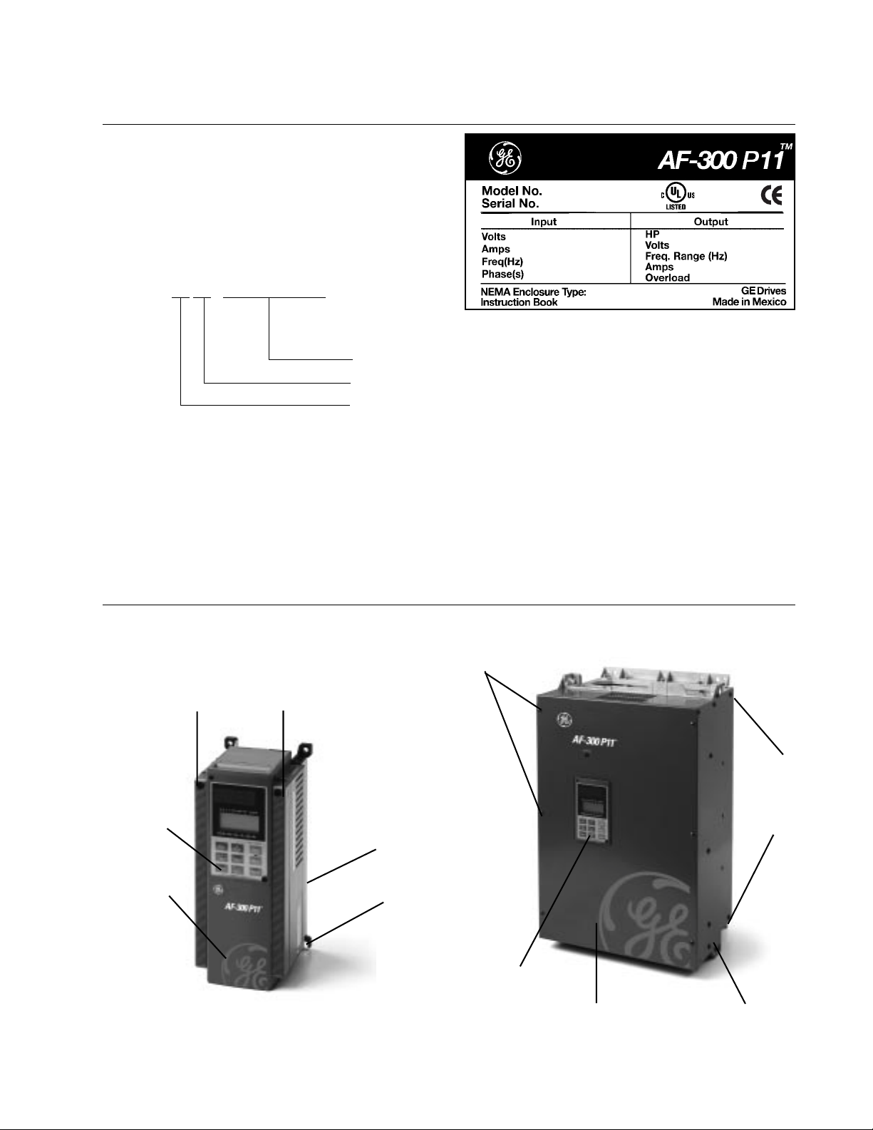
1. Check the ratings nameplate to confirm that the
delivered product is the one that was ordered.
SER. No. : 9 9 1 0 - 0 0 0 1 2 M 0 0 01
Ratings Nameplate
Production lot serial number
Production week: Fiscal week (01 to 53)
Production year: Last two digits of year (99 = 1999)
2. Check for damaged and/or missing parts upon delivery.
3. In addition to the drive unit and this manual, the package contains rubber bushings (for products with 30 Hp or less)
and a terminating resistor (1/2 W, 120 ohm). The terminating resistors for products with 30 Hp or less are packaged
separately. The terminating resistors for products with 40HP or more are installed internal to the drive unit. To
connect the internal terminating resistor, place hardware jumper J2 to the “ON” position. This terminating resistor is
required for RS485 RTU communication.
4. On drives rated 100 Hp and larger, a separately mounted DC Link Reactor is provided. The reactor should be
checked for proper rating before installation.
1.2 Appearance
Mounting screws of surface cover
Keypad Panel
Surface
cover
Mounting screws of
surface cover
(Total of 6 screws)
Lifting
Holes
(4 holes
total)
Intermediate cover
Ratings nameplate
Keypad Panel
30 HP or less
Data subject to change without notice 7/07. © 2007 GE Drives
40 HP or more
1-1
Surface Cover
Ratings
Nameplate
Page 15
1.3 Handling the Product
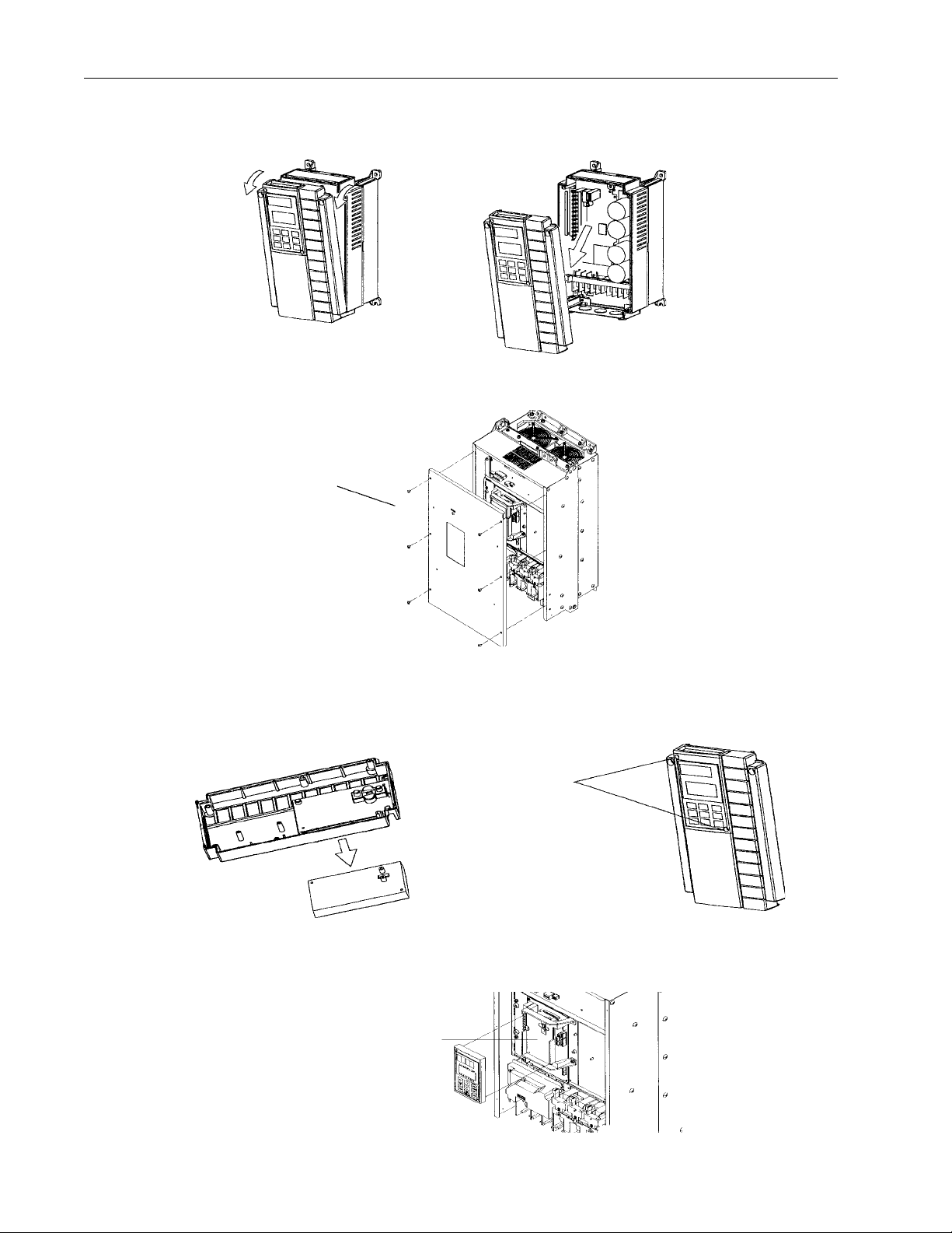
(1) Removing the Cover
For drives 30HP or less, loosen the cover mounting screws, then remove the cover by pulling from the top (see Figure
1.3.1).
Fig.1-3-1 Removing the Cover (for drives of 30HP or less)
For drives 40HP or more, first remove the six cover mounting screws, then remove the cover.
Mounting screws of service
cover (6 positions total)
Fig.1-3-2 Removing the Cover (for drives of 40HP or more)
(2) Removing the Keypad Panel
After removing the cover as explained in (1), loosen the keypad panel mounting screws and remove as shown in Figure
1.3.3 for drives 30HP or less.
Mounting screws of
Keypad panel
Fig.1-3-3 Removing the Keypad Panel (for drives of 30 HP or less)
For drives 40HP or more, loosen the keypad panel mounting screws and remove, using the finger holds on the keypad
panel case.
Keypad panel case
Fig.1-3-4 Removing the Keypad Panel (for drives 40HP or more)
1-2
Data subject to change without notice 7/07. © 2007 GE Drives
Page 16

1.4 Carrying
Carry the product by the main unit. Do not carry the product by its cover or parts other than the main unit. Use a crane or
hoist to carry a product equipped with hanging holes.
1.5 Storage
Temporary Storage
Temporary storage of this product must meet the conditions listed in Table 1-5-1.
Table 1-5-1 Storage Environment
Item Specifications
Ambient Temperature -10° to +50°C
(+14° to +122°F)
Storage Temperature
-25° to +65°C
(-4° to +149°F)
Relative Humidity
5 to 95%
2
Atmosphere The standard product must not be exposed to dust, direct sunlight, corrosive
gas, flammable gas, oil mist, vapor, water drops, or vibration. The salt content
in the atmosphere should be minimized.
Condensation or freezing, as a result of sudden temperature
changes, must not occur.
1
Note 1: The storage temperature applies only to short periods of time, such as during transport. Refer to comments on
extended storage guidelines.
Note 2: Since a large change in temperature within this humidity range may result in condensation or freezing, do not
store where such temperature changes may occur.
1. Do not place this product directly on the floor.
2. To store the product in an extreme environment, pack in vinyl sheeting, etc.
3. If the product is stored in a high-humidity environment, insert a drying agent (e.g., silica gel) and pack the product in
vinyl sheeting.
Long-term Storage
If the product is to be stored for an extended period of time after purchase, the method of storage depends primarily on
the storage location.
The general long-term storage method is as follows:
1. The above conditions for temporary storage must be satisfied.If the storage period exceeds three months, the upper
limit of ambient temperature must be reduced to 30°C (86°F) to prevent the deterioration of the electrolytic capacitors.
2. Pack the product thoroughly to eliminate exposure to moisture and include a drying agent to ensure a relative
humidity of about 70% or less.
3. Do not leave the product mounted in a control panel and exposed to the elements like moisture or dust (particularly
on a construction site). In this case, remove the product and store in a suitable environment.
4. Electrolytic capacitors will deteriorate if not provided with power for an extended period of time. Do not store
electrolytic capacitors for one year or longer without providing power.
Data subject to change without notice 7/07. © 2007 GE Drives
1-3
Page 17

1.6 AF-300 P11 Drive Ratings Efficiency and Watts Loss
HP Rating
Rated Output
Current (A)
Rated Output
Power (KVA)
Efficiency at 2KHz
(%)
Efficiency at
15KHz (%)
Watts Loss at
2KHz (W)
Watts Loss at
15KHz (W) Internal DB (W)
230VAC
0.25 1.5 0.59 92.0 90.5 25 30 N/A
0.5 3 1.1 93.5 91.7 35 45 N/A
15 1.9 94.9 94.0 50 60 N/A
28 3.1 95.7 94.1 80 110 N/A
311 4.3 95.9 94.9 110 140 N/A
517 6.7 96.2 95.4 170 210 N/A
7.5 22 8.7 96.2 95.2 210 280 N/A
10 29 11 96.5 95.3 290 370 N/A
15 42 16 96.4 95.2 410 550 N/A
20 55 21 96.9 95.9 500 670 N/A
25 67 26 96.8 95.8 630 840 N/A
30 78 31 96.5 95.5 770 1030 N/A
40 115 45 97.2 96.8 950 1100 N/A
50 145 57 97.0 96.7 1250 1400 N/A
60 180 71 97.1 96.6 1500 1750 N/A
75 215 85 97.3 96.6 1700 1950 N/A
100 283 112 97.4 97.0 2200 2500 N/A
125 346 137 97.4 97.2 2650 2800 N/A
150 415 165 97.4 97.3 3200 3350 N/A
2KHz (%) 10KHz (%) 2KHz (W) 10KHz (W)
2KHz (%) 6KHz (%) 2KHz (W) 6KHz (W)
460VAC
0.5 1.5 1.1 93.5 89.3 35 60 N/A
1 2.5 1.9 95.4 91.7 45 85 N/A
2 3.7 2.9 96.7 94.1 60 110 N/A
3 5.5 4.3 97.0 94.5 80 150 N/A
59 7.1 97.1 95.0 130 230 N/A
7.5 12.5 9.9 97.3 95.3 160 290 N/A
10 16.5 13.1 97.3 95.4 210 370 N/A
15 23 18.3 97.6 95.9 300 520 N/A
20 30 23.9 97.9 96.5 360 610 N/A
25 37 29.4 97.8 96.4 460 770 N/A
30 44 35 97.8 96.4 530 870 N/A
40 60 47 97.8 96.9 750 1050 N/A
50 75 59 97.7 96.9 950 1300 N/A
60 91 72 97.8 97.0 1100 1550 N/A
75 112 89 97.8 97.0 1350 1900 N/A
100 150 119 97.8 97.1 1800 2450 N/A
125 176 140 98.1 97.8 1850 2200 N/A
150 210 167 98.0 97.8 2400 2750 N/A
200 253 202 98.0 97.7 2900 3350 N/A
250 304 242 98.1 97.8 3250 3800 N/A
300 377 300 98.1 97.8 4250 4900 N/A
350 415 330 98.2 97.9 4350 5100 N/A
400 485 386 98.1 97.8 5100 5900 N/A
450 520 414 98.1 97.8 5700 6650 N/A
500 650 518 98.2 97.9 6900 8050 N/A
600 740 590 98.1 97.8 8050 9350 N/A
700 840 669 98.2 97.9 8900 10400 N/A
800 960 765 98.1 97.8 10300 12100 N/A
2KHz (%) 10KHz (%) 2KHz (W) 10KHz (W)
2KHz (%) 6KHz (%) 2KHz (W) 6KHz (W)
1-4
Data subject to change without notice 7/07. © 2007 GE Drives
Page 18
2. Installation Environment and Connection
Altitude Output current
reduction rate
3300 feet 1
(1000m or lower)
3300-4950 feet 0.97
(1000-1500m)
4950-6600 feet 0.95
(1500-2000m)
6600-8250 feet 0.91
(2000-2500m)
8250-9900 feet 0.88
(2500-3000m)
2.1 Operating Environment
Install this product in a location that meets the conditions listed in Table 2-1-1.
Table 2-1-1 Operating Environment
Item Specifications
Location Indoors
Ambient
Temperature
Relative
Humidity
Atmosphere The product must not be exposed to dust,
Altitude 1000 m (3300 feet) or lower - For altitude above
Vibration 3mm peak from 2 to 9Hz, 9.8m/s2 from 9 to 20Hz,
-10° to +50°C (+14° to +122°F) - for products of
30 HP or less, the ventilating covers must be
removed if ambient temperature exceeds
+40°C (104°F), NEMA Type 4 & 12 Unit -10° to
+40°C (+14° to +104°F)
5 to 95% (No condensation).
direct sunlight, corrosive gas, oil mist, vapor, or
water. There must be a minimum salt content in
the atmosphere. Do not store where
condensation may occur as a result of sudden
changes in temperature.
1000 m (3300 feet), see Table 2-1-2.
2m/s2 from 20-55Hz, 1m/s2 from 55 to 200Hzs.
CAUTION
Ensure that the drive and heat sink surfaces are kept
free of foreign matter such as lint, paper dust, small
chips of wood or metal, and dust. Fire or accident
may result.
Table 2-1-2 Output current reduction rate based on
altitude
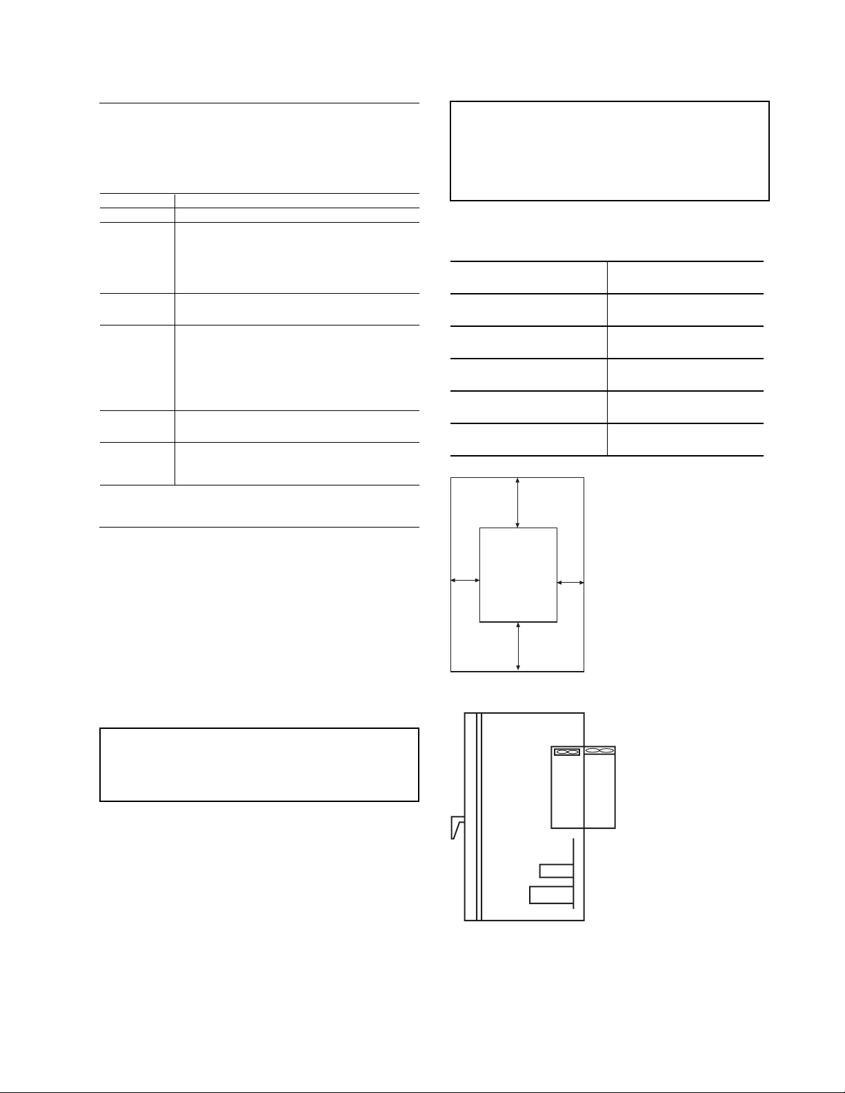
2.2 Installation Method
1. Securely fasten the product in an upright position on
a solid structure with the tag AF-300 P11 facing the
front. Do not turn the product upside down or install
in a horizontal position. Fig. 2-2-1
2. Since heat is generated during drive operation, the
spaces shown in Fig. 2-2-1 are required to ensure
sufficient cooling. Do not install the product beneath
a device sensitive to heat as heat radiates upward.
3. The heat sink may reach a temperature of 90°C
(+194°F) during drive operation. Ensure that the
material surrounding the product can withstand this
temperature.
WARNING
Install this product on nonflammable material such as
metal.
4. When installing this product in a control panel,
consider ventilation to prevent the drive’s ambient
temperature from exceeding the specified value. Do
not install the product in an area from which heat
cannot be sufficiently released.
5. If two or more drives must be installed in the same
device or control panel, arrange the units horizontally
to minimize the effect of heat. If two or more drives
must be installed vertically, place an insulated plate
between the drives to minimize the effect of heat.
6. When shipped from the factory, drives provide
internal cooling inside the panel. A drive of 30HP or
less can be converted to external cooling simply by
adding an optional mounting adapter.
Top
4” (100mm)
AF-300 P11 Drive
Left
X
Bottom
Right
X
4” (100mm)
Internal
Heat
Dissipation
(30%)
Internal
fan
Internal
air supply
Fig. 2-2-2 Through Panel Mount
Fig. 2-2-1 30 HP or less: Gap X can be
0. (side-by-side installation) 40HP or
more: Gap X >= 2.0” (50mm)
External
Heat
Dissipation
(70%)
Cooling fan
Heatsink
External
air supply
Data subject to change without notice 7/07. © 2007 GE Drives
2-1
Page 19
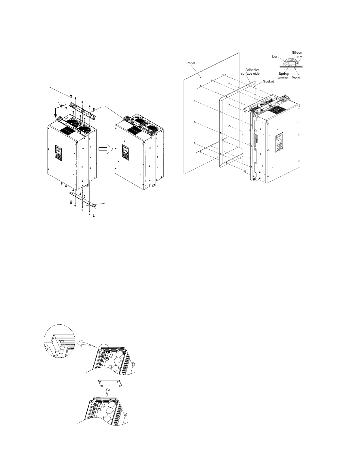
A drive of 40HP or more can be converted to external
cooling simply by moving the upper and lower mounting
brackets as shown in Fig. 2-2-3. Remove the M6 bracket
Installation of Open Type with NEMA 12 Heatsink Drive
(40 Hp and above)
screws, move the brackets, then secure the brackets
using the M5 case mounting screws. (The bracket screws
are no longer required after changing the bracket mounting position.)
Bracket Screws (M6)
Case mounting
screws (M5)
10 screws total
Mounting
Mounting
bracket
Fig. 2-2-3
In an external cooling system, a heat sink radiating about
70% of total drive heat (total loss) can be placed outside
the device or control panel, as shown in Fig. 2-2-2.
7. For drives of 30HP or less, remove the ventilating
covers if ambient temperature exceeds +40°C (104°F).
1. Removing the Ventilating Covers
One ventilating cover is mounted on top of the drive and
two or three are mounted at the bottom. Remove the
main cover and then remove ventilating covers by
popping out the cover inserts as shown in Fig. 2-2-4.
Fig. 2.2.6
Fig.2.2.5
1. Remove adhesive protection strip from gasket and
then mount gasket to panel/enclosure, carefully
aligning cutout and mounting holes.
2. Install the drive unit and tighten the mounting bolt
and nut. (Tightening torque: 119 lbs-inch [M8], 425
lbs-inch [M12] ). Mounting hardware to be supplied
by customer. (refer to figure 2.2.5)
3. After proper torque has been applied to all mounting
hardware, seal the outside end of the hardware with
silicon glue. Silicon glue to be supplied by the
customer. (Refer to Fig. 2.2.6)
Fig. 2-2-4 Removing the ventilating cover
2-2
Data subject to change without notice 7/07. © 2007 GE Drives
Page 20

2.3 Connection
Remove the main cover before connecting the terminal blocks as follows.
2-3-1 Basic Connection
1. Always connect power to the L1/R, L2/S, and L3/T main circuit power terminals on the drive. Connecting power to
another terminal will damage the drive. Check that the input voltage is within the maximum allowable voltage marked
on the nameplate, etc.
2. Always wire the ground terminal to ground to prevent problems such as fire or electric shock and to minimize noise.
3. Use a reliable crimp terminal for connection between a power terminal and a power wire.
4. After terminating the wiring connection, confirm the following:
a. Confirm that the connection is correct.
b. Confirm that all necessary connections have been made.
c. Confirm that there is no short-circuit or ground fault between the terminals and wire.
5. Connection modification after power-on.
The smoothing capacitor in the direct current portion of the main circuit cannot be discharged immediately after the
power is turned off. To insure safety, use a multimeter to check that the direct current (DC) voltage is lowered to the
safety range (25V DC or less) after the charge lamp goes off. Also, confirm that the voltage is zero before shortcircuiting. The residual voltage (electric charge) may cause sparks.
WARNING
Always connect a ground wire. Electric shock or fire may result. Ensure that a trained specialist
performs all wiring. Confirm that the power is turned off (open) before beginning any wiring operations.
Electrical shock may result.
Data subject to change without notice 7/07. © 2007 GE Drives
2-3
Page 21
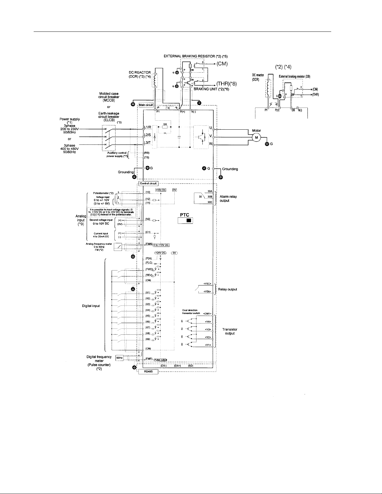
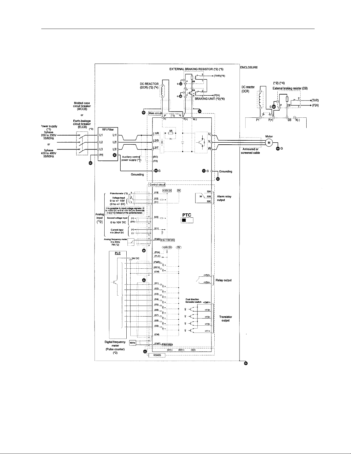
2.3.1 Basic Connection Diagram (Sink Logic)
20 Hp and above Up to 15 Hp
Note: The control circuit common terminals [11], (CM) and <CMY> are isolated
(*1) Use a drive with rated voltage matching the power supply voltage.
(*2) Use as required.
(*3) Use this peripheral device when necessary.
(*4) Remove the jumper wire between P1 and P(+) before connecting a DC REACTOR.
(*5) Be sure to use the braking unit (option) when connecting the external braking resistor (option)
(*6) Connect the braking unit to P(+) ans N(-). The auxiliary terminals [1] and [2] have polarity.
Connect them as shown in the figure above.
(*7) The drive can be operated without connecting the auxiliary control power supply.
(*8) Terminal (X1) to (X9) can be set to 9 (THR) - Braking unit thermal trip input.
(*9) If using V2 or C1, as a reference signal, they must be used exclusively.
(*10) It is possible to input voltage signals (0 to +10 VDC or 0 to +5 VDC) to terminals [12] [11] instead of the potentiometer
2-4
Data subject to change without notice 7/07. © 2007 GE Drives
.
Page 22
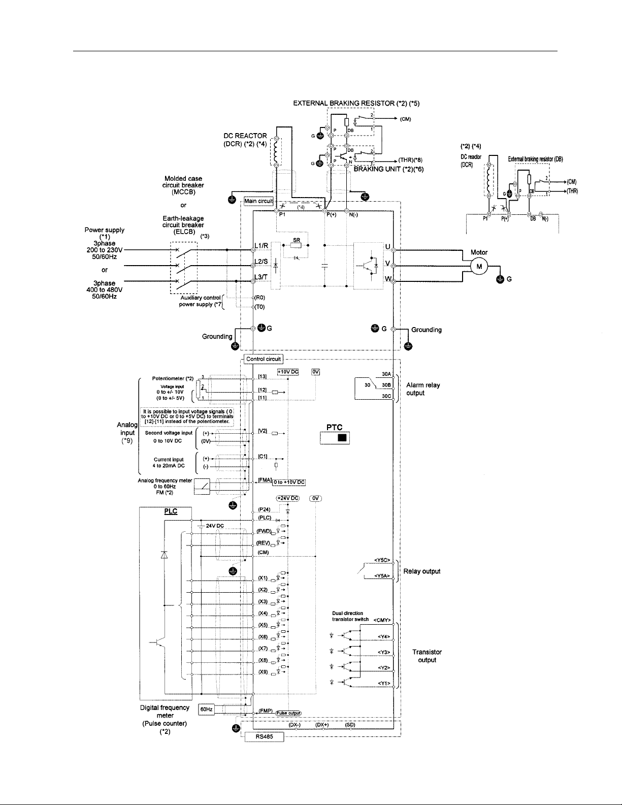
Basic Connection Diagram to PLC (Sink Logic)
20 Hp and above Up to 15 Hp
Data subject to change without notice 7/07. © 2007 GE Drives
See page 2-4 for notes
2-5
Page 23
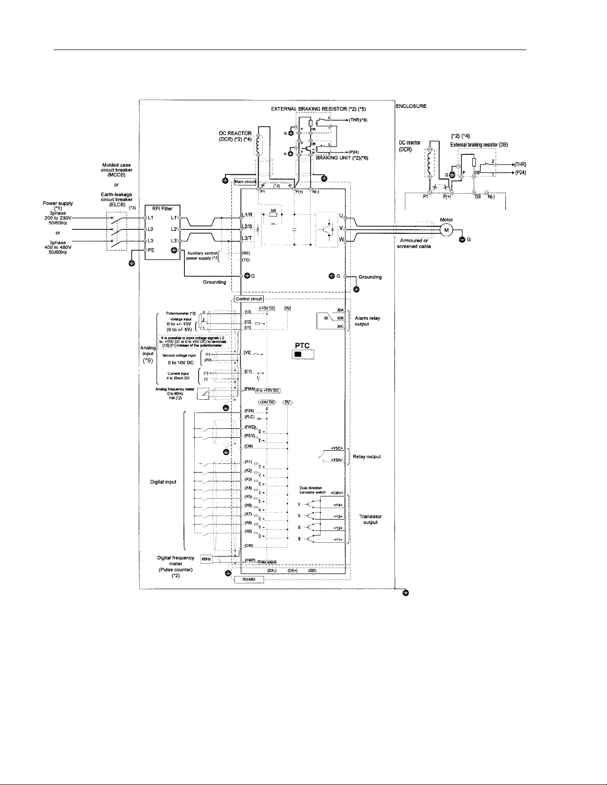
Basic Connection Diagram (Source Logic, Typically used in Europe)
20 Hp and above Up to 15 Hp
Note: The control circuit common terminals [11], (CM) and <CMY> are isolated
(*1) Use a drive with rated voltage matching the power supply voltage.
(*2) Use as required.
(*3) Use this peripheral device when necessary.
(*4) Remove the jumper wire between P1 and P(+) before connecting a DC REACTOR.
(*5) Be sure to use the braking unit (option) when connecting the external braking resistor (option).
(*6) Connect the braking unit to P(+) ans N(-). The auxiliary terminals [1] and [2] have polarity.
Connect them as shown in the figure above.
(*7) The drive can be operated without connecting the auxiliary control power supply.
(*8) Terminal (X1) to (X9) can be set to 9 (THR) - Braking unit thermal trip input.
(*9) If using V2 or C1, as a reference signal, they must be used exclusively.
(*10) It is possible to input voltage signals (0 to +10 VDC or 0 to +5 VDC) to terminals [12] [11] instead of the potentiometer
2-6
Data subject to change without notice 7/07. © 2007 GE Drives
.
Page 24
Basic Connection Diagram to PLC (Source logic, Typically used in Europe)
20 Hp and above Up to 15 Hp
Data subject to change without notice 7/07. © 2007 GE Drives
See page 2-6 for notes
2-7
Page 25

2.3.2 Connecting the Main Circuit and Ground Terminals
Table 2.3.1 Functions of main circuit terminals and ground termnals
Symbol Terminal Name Description
L1/R,L2/S,L3/T Main circuit power terminals Connects a 3-phase power supply
U,V,W Inverter output terminals Connects a 3-phase motor
R0,T0 Input terminals for auxiliary control power Connects a backup AC power supply to the control
P1,P(+) DC reactor terminals Connects the optional power correcting DC reactor
circuit (not supported for drives of 1 Hp or less)
P(+),DB Terminals for external braking resistor Connects the optional external braking resistor (for
P(+),N(-) Terminals for DC link circuit Supplies DC link circuit voltage to the external
GGround terminal Connects the drive chassis (case) to ground.
drives of 15 Hp or less)
braking unit (option) or power regeneration unit
(option).
(1) Main circuit power terminals (L1/R, L2/S, L3/T)
1. Connect these terminals to the power supply via a molded-case circuit breaker or ground-leakage circuit breaker for
circuit protection. Phase-sequence matching is unnecessary.
2. To insure safety, a magnetic contactor should be used to disconnect the drive from the power supply when the drive
protective function activates.
3. Use control circuit terminal FWD/REV or the RUN/STOP key on the keypad panel to start or stop the drive. The main
circuit power should be used to start or stop the drive only if absolutely necessary and then should not be used
more than once every hour.
4. If you need to connect these terminals to a single-phase power supply, please contact the factory.
(2) Drive output terminals (U, V, W)
1. Connect these terminals to a 3-phase motor in the correct phase sequence. If the direction of motor rotation is
incorrect, exchange any two of the U, V, and W phases.
2. Do not connect a power factor correction capacitor or surge absorber to the drive output.
3. If the cable from the drive to the motor is very long, a high-frequency current may be generated by stray capacitance
between the cables and result in an overcurrent trip of the drive, an increase in leakage current, or a reduction in
current indication precision.
When a motor is driven by a PWM-type drive, the motor terminals may be subject to surge voltage generated by drive
element switching. If the motor cable (with 460V series motors, in particular) is particularly long, surge voltage will
deteriorate motor insulation. To prevent this, use the following guidelines:
Drives 7.5 HP and larger
Motor Insulation Level 1000V 1300V 1600V
460 VAC Input Voltage 66 ft (20 m) 328 ft (100 m) 1312 ft (400 m) *
230 VAC Input Voltage 1312 ft (400 m) * 1312 ft (400 m) * 1312 ft (400 m) *
Drives 5 HP and smaller
Motor Insulation Level 1000V 1300V 1600V
460 VAC Input Voltage 66 ft (20 m) 165 ft (50 m) * 165 ft (50 m) *
230 VAC Input Voltage 328 ft (100 m) * 328 ft (100 m) * 328 ft (100 m) *
* For this case the cable length is determined by secondary effects and not voltage spiking.
Note: When a motor protective thermal O/L relay is inserted between the drive and the motor, the thermal O/L relay may
malfunction (particularly in the 460V series), even when the cable length is 165 feet (50m) or less. To correct, insert a
filter or reduce the carrier frequency. (Use function code “F26 Motor sound”.)
2-8
Data subject to change without notice 7/07. © 2007 GE Drives
Page 26

(3) Input terminals for auxiliary control power
(R0 and T0)
The drive operates even if power is not provided to these
terminals. If a protective circuit operates, and the mag-
netic contactor on the drive’s power is opened (off), the
inverter control circuit power, the alarm output (30A, B,
and C), and the keypad panel display goes off. To prevent
this, the main circuit AC power must also be supplied as
auxiliary control power to the auxiliary control power input
terminals (R0 and T0).
1. To ensure effective noise reduction when using a
radio noise filter, the output power from the filter must go
to the auxiliary control power input terminals. If these
terminals are connected to the input side of the filter, the
noise reduction effect deteriorates.
(4) DC reactor terminals (P1 and P(+))
1. Before connecting a power factor correcting DC
reactor (optional) to these terminals, remove the
factory-installed jumper.
2. If a DC reactor is not used, do not remove the jumper.
Note: For drives of 100 Hp or more, the DC reactor is
provided as a separate standard component and should
always be connected to the terminals. DC reactor is
provided as open type, enclosure to be provided by other.
CAUTION
A DC reactor does not come with drives rated less
than 100 Hp, however, use a DC reactor or AC
reactor under the following conditions otherwise the
drive may be damaged or malfunction.
1) Used when the capacity of the power supply transformer exceeds 500k VA and exceeds the rated
capacity of the drive tenfold.
2. Used when a thyrister converter is connected as a
common load on the same transformer.
3. Used to prevent a drive OV trip from occuring when
the power factor capacitor in the power line is
switched on and off.
4. Used when the voltage imbalance exceds 3%.
Fig. 2-3-2 Connection the auxiliary control-power input terminals
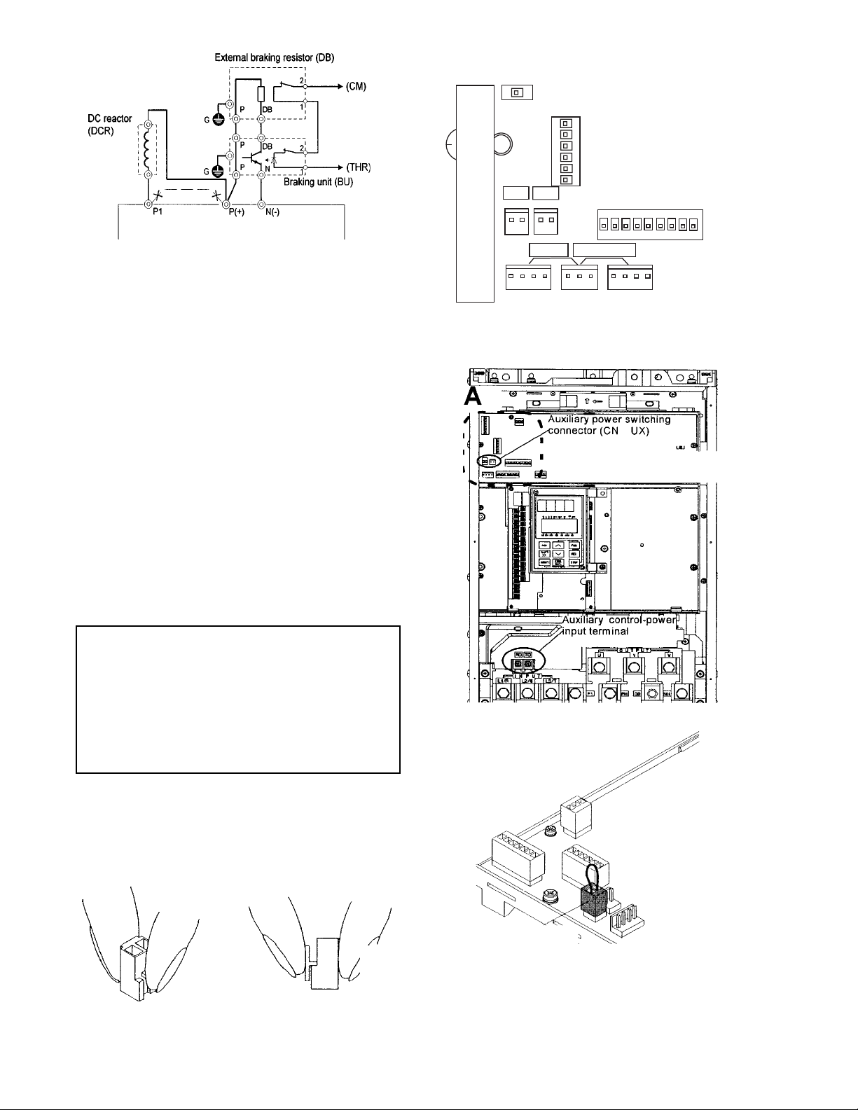
(6) Terminals for DC link circuit (P(+) and N(-))
The P11 drive of 20 Hp or more, does not contain a drive
circuit for the braking resistor. To improve braking
performance, an external braking unit (option) and an
external braking resistor (option) must be installed.
1. Connect terminals P(+) and N(-) on the braking unit to
terminals P(+) and N(-) on the drive. The wiring length
(twisted pair cables, etc.) should not exceed 16.5 feet
(5m).
2. Connect terminals P(+) and DB on the braking
resistor to terminals P(+) and DB on the braking unit.
The wiring length (twisted pair cables, etc.) should
not exceed 33 feet (10m). If terminals P(+) and N(-) on
the drive are not used, leave the terminals open. If
P(+) is connected to N(-), or the braking resistor is
connected directly, the resistor will burn up.
3. Auxiliary contacts 1 and 2 of the braking unit have
polarity.
4. Refer to DB unit instruction book for paralleled
resistors.
Note: Braking units and resistors are rated on degree of
braking, duration and system frequency of braking cycle.
Verify units meet application requirements.
Imbalance rate
between phase [%] =
(Max. voltage [V] - Min. voltage [V]
3-phase average voltage [V]
x 100%
(5) Terminals for external braking resistor (P(+) and
DB) (15 Hp or less)
The P11 drive 15 Hp or less, does not contain a braking
resistor. To improve braking performance, an external
braking resistor must be installed.
1. Connect terminals P(+) and DB on the external
braking resistor to terminals P(+) and DB on the drive.
2. The wiring length (twisted pair cables, etc.) should
not exceed 16.5 feet (5m).
Data subject to change without notice 7/07. © 2007 GE Drives
2-9
Fig. 2-3-3
Fig. 2-3-4 Connection (15 Hp or less)
Page 27
<Enlarged view of part A>
+
U2
U1
When shipped from the
factory, CN UX is connected to the U1 side.
Fig. 2-3-5 Connection 20 Hp or more, 100 Hp or more
parallel resistors, 200 Hp or more parallel braking units.
(7) Ground terminal
The grounding connector should be sized in accordance
with the NEC or Canadian Electrical Code. The connection should be made by a UL listed or CSA certified
<3D view of part A>
Factory Shipment Status Connector CN UX: U1
closed-loop terminal connector sized for the wire gauge
involved. The connector is to be fixed using the crimp tool
specified by the connector manufacturer.
(8) Auxiliary power switching connector (CN UX) (for
drives of 40 Hp or more)
When a drive of 40 Hp or more requires main circuit
power voltage as listed below, disconnect the auxiliary
power switching connector CN UX from U1 and connect
to U2. For the switching method, see Fig. 2-3-6.
Table 2-3-3 Main Voltage Requiring Auxiliary Power Switching Connector
Frequency [Hz] Power Voltage Range [VAC]
50 380 - 398
60 380 - 430
CAUTION
• Check that the number of phases and rated
voltage match those of the AC power supply.
• Do not connect the AC power supply to the
output terminals (U, V, W). Injury may result.
• Do not directly connect a braking resistor to
the DC terminals (P[+] and N[-]). Fire may
result.
RO-TO
L1/R-L3T
The switching connectors are mounted on the power PCB
above the control PCB as shown on the right.
Note: To remove a connector, unlock the connector (using
the locking mechanism) and pull. To install, firmly push the
connector until it clicks into place.
CN UX
2-10
CN UX (red)
Fig. 2-3-6
Data subject to change without notice 7/07. © 2007 GE Drives
Page 28
2.3.3 Connecting the Control Terminals
Table 2.3.3 lists the functions of the control circuit terminals. A control circuit terminal should be connected according
to its function setting.
Table 2-3-3
Classification Symbol Terminal Name Function
Analog input 13 Potentiometer power supply Used for +10V DC power supply for frequency setting POT
Te rm inal
(resistance of 1 to 5k Ohms)
12 Voltage input 1. Frequency is set according to the analog input voltage
supplied from an external circuit.
- 0 to +10V DC / 0 to 100%
- Reversible operation using positive and negative signals:
0 to +/- 10V DC / 0 to 100%
- Reverse operation: +10 to 0V DC / 0 to 100%
2. Input feedback signal for PID control is input.
3. The analog input value from the external circuit is used
for torque control
* Input resistance: 22 k Ohms
V2 Voltage input ¨ Frequency is set according to the analog input voltage
supplied from an external circuit.
- 0 to +10V DC/0 to 100%
- Reverse operation: +10 to 0V DC/0 to 100%
* Use only one terminal - V2 or C1 Exclusively
* Input resistance: 22 k Ohms
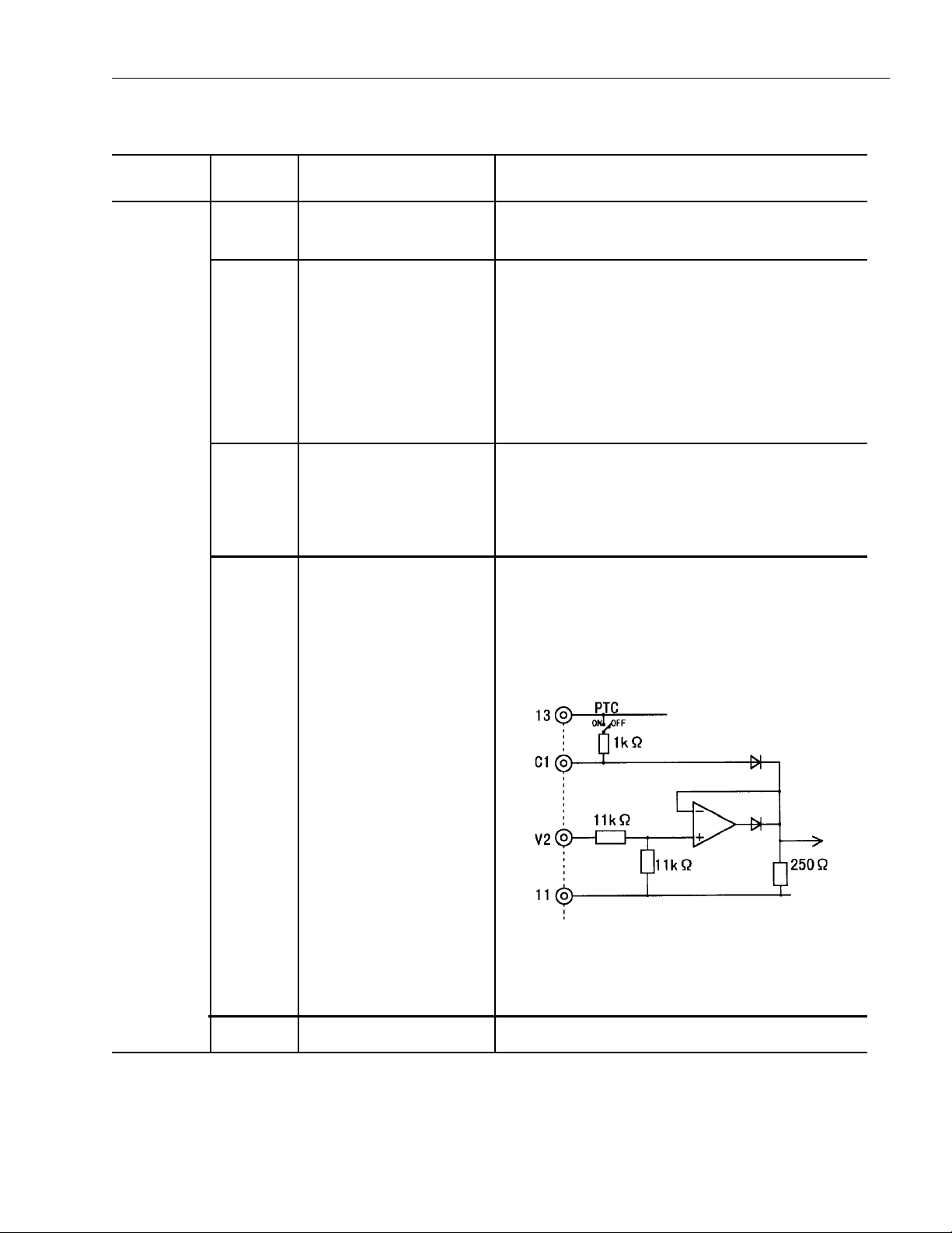
C1 Current input 1. Frequency is set according to the analog input current supplied
from an external circuit.
- 4 to 20mA DC / 0 to 100%
- Reverse operation: 20 to 4mA DC / 0 to 100%
2. The feedback signal for PID control is input.
3. PTC thermistor input
11 Analog input common Common terminal for analog input signals
Data subject to change without notice 7/07. © 2007 GE Drives
* Use only one terminal - V2 or C1 Exclusively
* Input resistance: 250 Ohms
* PTC switch is off when PTC function is not used
2-11
Page 29
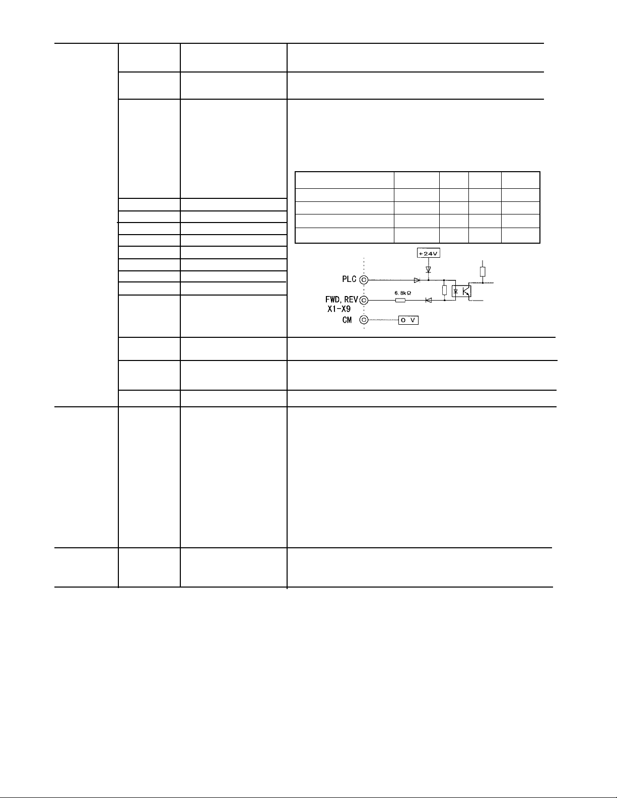
Digital input FWD Forward operation / Used for forward operation (when FWD-CM is on) or
Stop command deceleration and stop (when FWD-CM is opened)
REV Reverse operation / Used for reverse operation (when REV-CM is on) or
Stop command deceleration and stop (when REV-CM is opened)
X1 Digital input 1 The coast-to-stop command, external alarm, alarm reset, multi-
step frequency selection, and other functions (from an external
circuit) can be assigned to terminals X1 to X9. For details, see
"Setting the Terminal Functions E01 to E09" in Section 5.2
Function Explanation.
<Specifications of digital input circuit>
Item min. typ. max.
Operating voltage ON 0V – 2V
X2 Digital input 2
X3 Digital input 3
X4 Digital input 4
X5 Digital input 5
Maximum load current ON – 3.2mA 4.5 mA
Leakage current OFF – – 0.5 mA
OFF 22V 24V 27V
X6 Digital input 6
X7 Digital input 7
X8 Digital input 8
X9 Digital input 9
P24 Control Unit power Supply +24VDC power supply for control input. Maximum output current 100mA
PLC PLC signal power Used to connect PLC power supply for output signals; rated nominal
voltage = 24 VDC (22 to 27 V DC range) at sink logic operation.
CM Digital input common Common terminal for digital input signals and P24
Analog output FMA Analog monitor Outputs monitor signal using analog DC voltage 0 to +10V DC.
The signal indicates one of the following:
(11: common - Output frequency (before slip compensation)
terminal) - Load factor
- Output frequency (after slip compensation)
- Power consumption
- Output current
- PID feedback value
- Output voltage
- PG feedback value
- Output torque
- DC link circuit voltage
* Connectable impedance: min. 5k ohms
Pulse output FMP Frequency monitor Outputs a monitor signal using the pulse waveform.
(CM: common (pulse waveform output) This signal has the same function as the FMA signal.
terminal)
2-12
Data subject to change without notice 7/07. © 2007 GE Drives
Page 30
Transistor Y1 Transistor output 1 A running signal, frequency equivalence signal, overload early
warning output signal, and other signals from the drive are output
(as transistor output) to arbitrary ports. For details, see "Setting the
Terminal Functions E20 to E23" in Section 5.2 Function Explanation.
* <Specifications of transistor output circuit>
Item min. typ. max.
Operating voltage ON – 1V 2V
OFF – 24V 27V
Y2 Transistor output 2
Y3 Transistor output 3
Y4 Transistor output 4
Maximum load current ON – – 50 mA
Leakage current OFF – – 0.1 mA
CMY Transistor output common Common terminal for transistor output signals. This terminal is
Relay output 30A,30B,30C Alarm outputs for any fault. If the drive is stopped by an alarm (protective function), the alarm
Y5A,Y5C Multi-purpose signal These signals can be output similar to the Y1 to Y4 signals above.
Communic- DX+,DX– RTU communication Input / output signal terminals for RTU communication input / output
ation Up to 31 inverters can be connected using the daisy chain method.
SD Communication cable Terminal for connecting the cable shield. The terminal is electrically
shield connection terminal floating.-
(1) Analog input terminals (13, 12, C1, and 11)
1. These terminals receive low level analog signals that
may be affected by external noise. The cables must
be as short as possible (20 meters or less), must be
shielded, and the shields must be grounded. If the
cables are affected by external induction noise, the
shielding effect may be improved by connecting the
shield to terminal [11].
insulated from terminals (CM) and [11].
signal is output from the relay contact output terminal (1SPDT).
Contact rating: 250 VAC, 0.3A,cosØ = 0.3, 48 VDC, 0.5A for CE
Marking
An excitation mode (excitation at alarm occurrence or at normal
operation) can be selected.
The contact rating is the same as that of the alarm output above.
Drive
Shielded wires
VR
1k to
5K ohms
Fig. 2-3-9
13
12
11
2. If contacts must be connected to these circuits, twin
(bifurcated) contacts for handling low level signals
must be used. A contact must not be connected to
terminal [11].
3. If an external analog signal output device is connected to these terminals, it may malfunction as a
result of drive noise. To prevent malfunction, connect
a ferrite core or capacitor to the external analog
signal output device.
Data subject to change without notice 7/07. © 2007 GE Drives
Fig. 2-3-10 Example of Noise Prevention
2-13
Page 31

(2) Digital input terminals (FWD, REV, X1 to X9, PLC,
and CM)
1. Digital input terminals (e.g., FWD, REV, X1 to X9) are
generally turned on or off by connecting or disconnecting the line to or from the CM terminal.
If digital input terminals are turned on or off by
switching the PLC’s open collector output using an
external power supply, a resulting bypass circuit may
cause the drive to malfunction. To prevent a malfunction, connect the PLC terminal as shown in Fig. 2-3-
11.
Fig. 2-3-11 Prevention of Bypass Current by External Power
2. When using a contact input, a high-quality relay with
reliable contacts must be used.
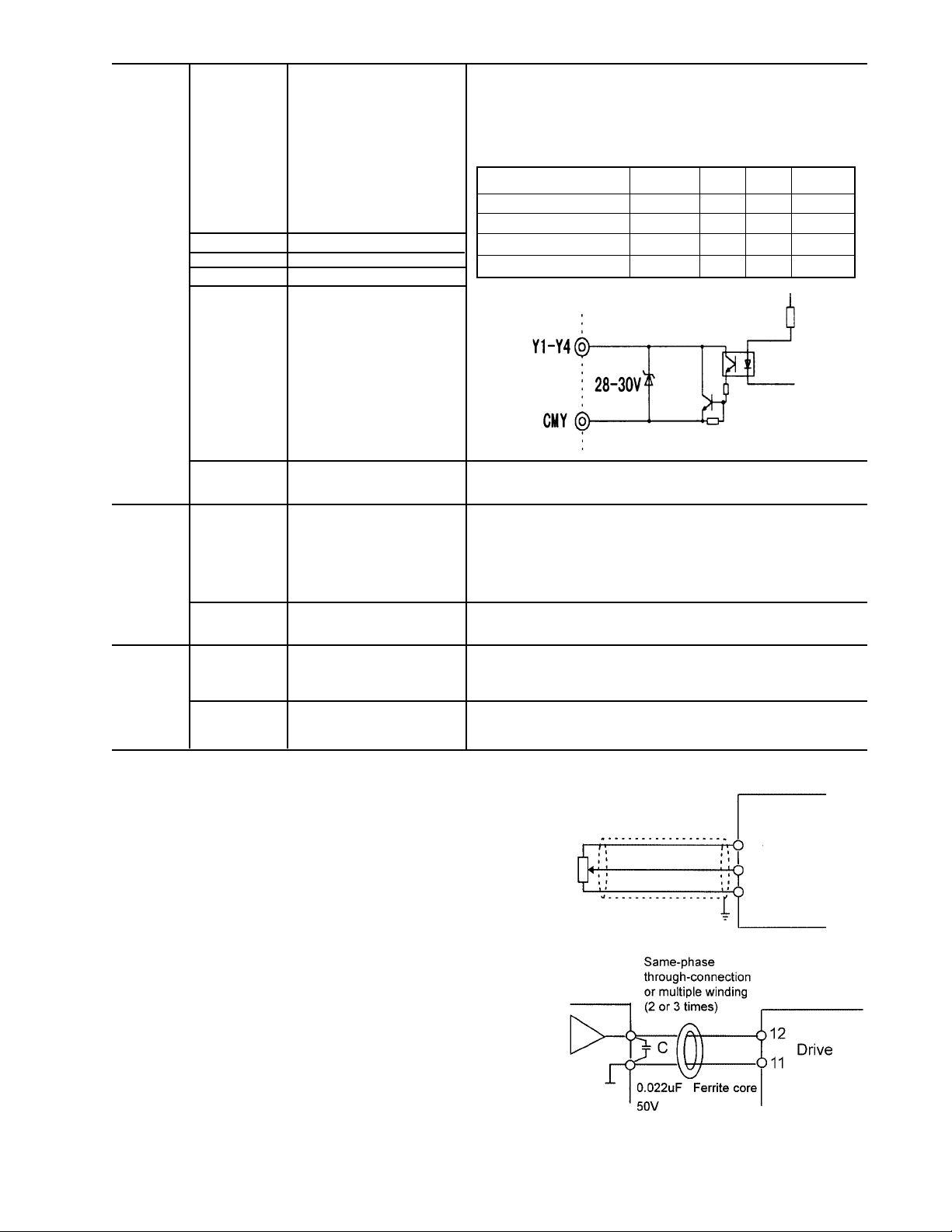
(3) Transistor output terminals (Y1 to Y4, CMY)
1. These terminals have a circuit configuration as shown
in Table 2-3-3, "Transistor Output". Confirm the
polarity of the external power supply.
2. To connect a control relay, connect a surge absorbing
diode to both ends of its exciting coil.
(4) Sink or Source Logic Selection.
1. Set SWI for Sink or Source Connection to the PLC.
The factory default setting is Sink and this instruction
manual explains Sink logic function only.
2. When you need to connect source type logic, refer to
Basic Connection Diagram Fig. 2-3-3 and Fig. 2-3-4
and Technical Information Manual. (Sink Logic is
commonly used in the USA and Source Logic is
commonly used in Europe.)
(5) Others
1. To prevent a malfunction as a result of noise, control
terminal cables must be placed as far as possible
from the main circuit cables.
2. The control cables inside the inverter must be
secured to prevent direct contact with the main circuit
(e.g., main circuit terminal block).
(6) Wiring of control circuit (inverter of 40 Hp or more)
1. Pull out the control circuit wiring along the left panel
as shown in Fig. 2-3-12.
2. Secure the cable to cable binding hole A (on the left
wall of the main circuit terminal block) using a cabletie
(e.g., Insulock). The cable-tie must not exceed 0.14"
(3.5mm) in width and 0.06" (1.5mm) in thickness.
3. When the optional PC board is mounted, the signal
lines must be secured to cable binding hole B.
Fig. 2-3-12 The Control Wiring Route
Cable ties
wiring
Cable
Cable binding
Hole B
Fig. 2-3-13 Securing Positions for Inverter Control Circuit Wiring (40 HP or more)
binding
Hole A
WARNING
Control lines generally do not have enhanced
insulation. If the insulation of a control line is
damaged, the control signals may be exposed to
high voltage in the main circuit. The Low Voltage
Directive in Europe also restricts the exposure to
high voltage. Electric shock may result
CAUTION
The inverter, motor, and cables generate noise.
Check that the ambient sensors and devices do
not malfunction. Accident may result.
2-14
Data subject to change without notice 7/07. © 2007 GE Drives
Page 32

2.3.4 Terminal Configuration
(1) Main circuit terminals
1/4 to 1 Hp 230 VAC
1/2 to 1 Hp 460 VAC
L1/R L2/S L3/T DB P1 P(+) N(–) U V W
G
G
Screw size M3.5
2 to 5 Hp 230 VAC
2 to 5 Hp 460 VAC
L1/R L2/S L3/T DB P1 P(+) N(–) U V W
R0 T0
Screw size M3.5
G
Screw size M4
7.5 to 15 Hp 230 VAC
7.5 to 15 Hp 460 VAC
L1/R L2/S L3/T DB P1 P(+) N(–) U V W
R0 T0
Screw size M3.5
G G
Screw size M5
60 To 100 Hp 230 VAC
125 to 200 Hp 460 VAC
L1/R L2/S L3/T DB P1
G G
125 Hp 230 VAC
R0 T0
L1/R L2/S L3/T P1 P(+) N(-) U V W
G
150 Hp 230 VAC
250 to 450 Hp 460 VAC
R0 T0
L1/R
G G
R0 T0
Screw size M4
G G
Screw size G = M10
Other terminals = M12
Screw size M4
L2/S L3/T
Screw size G = M10
Other terminals = M12
U V W
P(+) N(–)
Screw size G = M8
Other terminals = M10
U
P1
VW
P(+)
N(-)
20 to 30 Hp 230 VAC
20 to 30 Hp 460 VAC
L1/R L2/S L3/T DB P1 P(+) N(–) U V W
R0 T0
Screw size M3.5
G
Screw size M6
G
40 to 50 Hp 230 VAC
40 to 100 Hp 460 VAC
Screw size M4
R0 T0
L1/R L2/S L3/T DB P1
U V W
P(+) N(–)
G G
Screw size M8
500, 600 Hp 460 VAC
R0 T0
L1/R L2/S
L1/R
L2/S L3/T
Screw size M4
G G
700, 800 Hp 460 VAC
R0 T0
L1/R
L2/S L3/T
L2/S L3/T
L1/R
Screw size RO,TO = M4 G = M10
Other terminals = M12
L3/T
P1
VW
P(+)
N(-)
P(+)
U
N(-)
U
VW
P(+)
N(-)
U
N(-)
V
U
G
V
G
P1
P1
Screw size G = M10
Other terminals = M12
P1
P(+)
W
W
Data subject to change without notice 7/07. © 2007 GE Drives
2-15
Page 33

(2) Control circuit terminals
30A Y5A CMY Y3 Y1 C1 FMA FMP PLC X1 X2 X3 X4 X5 X6 X7 X8 X9
30C 30B Y5C Y4 Y2 11 12 13 V2 CM CM FWD REV P24 P24 DX- DX+ SD
2.3.5 AF-300 P11 Drive Cable Size, Tightening Torque and Circuit Protection Rating
HP
L1/R, L2/S, L3/T
(Nominal)
230 VAC Input
0.25 3 3 3 15 10.6 (1.2) 10.6 - 6.2 (0.7) 16 16 - 22
0.5 5 6 3 15 (1.2) - 110 15320 - 21520330 20.8 (2.36) 20.8 10.6 (1.2) 14
32030340 (2.36) 14 14
535 50360 10
7.5 60 80 3 100 31.0 (3.5) 31.0 8
10 70 125 3 125 (3.5) 6
15 100 150 3 175 4
20 125 200 3 225 3
25 150 225 3 250 2
30 175 250 3 300 1
40 200 - 5 200 4/0 1/0 2/0 10
50 225 - 5 225 Qty2 - 1 3/0 4/0 10
60 300 - 5 300 239(27) 119(13.5) 119 Qty2 - 2/0 4/0 Qty2 - 1
75 350 - 5 350 (13.5) Qty2 - 3/0 Qty2 - 1/0 Qty2 - 2/0 8
100 300 - 5 300 Qty 2 - 2/0 Qty2 - 3/0 Qty2 - 4/0 6
125 400 - 5 400 425(48) 239(27) Qty2 - 4/0 Qty2 - 4/0 Qty2 - 250 4
150 450 - 5 450 Qty2 - 250 Qty2 - 300 Qty2 - 350
460 VAC Input
0.5 3 3 3 15 10.6 (1.2) 10.6 - 6.2 (0.7) 16 16 - 22
15 6315 (1.2) - 21010315 20.8 (2.36) 20.8 10.6 (1.2) 14
31515320 (2.36)
520 25335 14 14
7.5 30 45 3 50 31.0 (3.5) 31.0 12
10 40 60 3 70 (3.5) 10
15 50 90 3 90
20 70 110 3 110 8
25 80 125 3 150 6
30 100 125 3 175 4
40 100 - 10 100 119(13.5) 2 3 3 10
50 125 - 10 125 1 2 2
60 150 - 10 150 51.3 2/0 2 1
75 175 - 10 175 (5.8) 3/0 1/0 2/0
100 150 - 10 150 2/0 3/0 4/0
125 200 - 10 200 239(27) 119(13.5) 3/0 4/0 Qty2 - 1 10
150 225 - 10 225 239(27) 119 Qty2 - 1/0 Qty2 - 1/0 Qty2 - 1/0 8
200 300 - 10 300 (13.5) Qty2 - 1/0 Qty2 - 2/0 Qty2 - 3/0
250 400 - 10 400 425(48) 239 Qty2 - 3/0 Qty2 - 3/0 Qty2 - 4/0 6
300 450 - 10 450 (27) Qty2 - 4/0 Qty2 - 250 Qty2 - 300 4
350 500 - 10 500 Qty2 - 250 Qty2 - 300 Qty2 - 350
400 600 - 10 600 (*3) Qty2 - 350 Qty2 - 350 Qty2 - 500 (*3)
450 700 - 10 700 Qty2 - 350 Qty2 - 400 Qty2 - 500
500 700 - 10 700 Qty2 - 500 Qty3 - 300 Qty3 - 300
600 1000 - 10 1000 Qty3 - 300 Qty3 - 350 Qty3 - 500
700 1000 - 10 1000 Qty3 - 400 Qty3 - 500 Qty3 - 600
800 1200 - 10 1200 Qty3 - 500 Qty3 - 600 Qty3 - 600
(*1)Class J Fuse or Circuit Breaker reted 600V with the maximum current rating as shown in the above table shall be connected to the drive for 30HP and less.
(*2)Based on GE Fuji standard DB unit and DB resistor designs. Other rating require careful review.
(*3) Consult factory
Device ratings such as system coordination, short-circuit rating and type must be carefully reviewed by the user.
Wire size from NEC tables 310-16. Copper wire rated 60 Deg. C for 100amps or less, 75 Deg. C for over 100 amps in 30 Deg. C ambient and 1.25 times Drive rated amps.
These are minimum wire sizes : consult and conform to local and national codes.
Input Fuse
L1/R, L2/S, L3/T
(Maximum) (*1)
Incoming Device Tightening Torque lb-Inch (Nm) Cable size AWG
Auxiliary
Input
R0, T0
Input Circuit
Breaker (*1)
L1/R, L2/S,
L3/T, U, V,
W, P1, P(+)
51.3 (5.8)
119(13.5)
51.3 (5.8)
E(G)
DB circuit
(*2) P(+),
N(-), DB
R0, T0 Control
L1/R, L2/S,
L3/T
DC Reactor
P1, P(+)
DB circuit
(*2) P(+),
N(-), DB
R0,
T0
ControlU, V, W
2-16
Data subject to change without notice 7/07. © 2007 GE Drives
Page 34

2.3.6 DC Link Reactor
Dimensions in inches
Terminal
Height
Width
Hp
230V P11
100 DCR2-75B 7.87 10.63 7.09 37 55
125 DCR2-90B 7.09 11.02 8.46 37 57
150 DCR2-110B 7.48 12.99 9.05 46 67
460V P11
100 DCR4-75B 7.48 10.63 6.89 35 58
125 DCR4-90B 7.48 11.02 7.87 44 64
150 DCR4-110B 7.48 11.02 7.87 46 73
200 DCR4-132B 7.87 11.02 8.07 55 84
250 DCR4-160B 8.27 12.6 8.07 68 90
300 DCR4-200B 8.27 12.99 9.06 75 126
350 DCR4-220B 8.66 13.78 9.06 81 131
400 DCR4-280B 8.66 14.57 9.65 95 133
450 DCR4-280B 8.66 14.57 9.65 95 150
500 DCR4-355B 9.84 12.99 8.78 99 205
600 DCR4-400B 9.84 13.78 9.17 106 215
700 DCR4-450B 10.63 13.78 10.35 121 272
800 DCR4-500B 11.1 14.17 10.35 143 292
Model No. Width Depth Height Weight Loss [W]
Depth
Note:
• AF-300 P11 Drives rated 100 Hp and above are furnished with a DC link reactor. This reactor must be installed
between terminal P1 and P+ prior to commissioning of the Drive.
• The weight of the DC Link Reactor is not included with that of the Drive.
• DC Link Reactor is provided as open type and is separately mounted. Enclosure to be provided by others.
Data subject to change without notice 7/07. © 2007 GE Drives
2-17
Page 35

Notes
2-18
Data subject to change without notice 7/07. © 2007 GE Drives
Page 36

3. Operation
3.1 Inspection and Preparation Before Operation
Check the following before operation:
1. Check that the connections are correct.
In particular, check that the power supply is not connected to any of
the U, V, or W output terminals and that the ground terminal is
securely grounded.
2. Check for short circuits and ground faults between the terminals
and sections under power.
3. Check for loose terminals, connectors, or screws.
4. Check that the motor is disconnected from the mechanical
equipment.
5. Turn off switches before turning on power to ensure that the drive
will not start or operate abnormally at power-on.
6. Check the following after power-on:
a. No alarm message is displayed on the keypad panel (see Figure
3-1-2).
b. The fan inside the drive is rotating. (For drives with 2Hp or
more.)
WARNING
Be sure to have the drive cover in place before turning on the power
(closed). Never remove the cover while power is applied to the drive.
To ensure safety, do not operate switches with wet hands. Electric
shock may result.
Drive
L1/R, L2/S, L3/T, U, V, W
power
Fig. 3-1-1 Drive connection
motor
3.2 Operation Method
There are various methods of operation. Select a method of
operation according to the operating requirements and specifications; refer to Section 4-2 Operating the Keypad Panel, and
Chapter 5 Function Selection. Table 3-2-1 lists general methods
of operation.
3.3 Trial Run
Once inspection is completed (see Section 3-1), proceed with a
trial run. The motor is initially disconnected and the drive is
operated (factory setting) using the keypad panel.
1. Turn power on and confirm that the LED monitor display 0.00
Hz is blinking.
2. Set the frequency to about 5 Hz using
3. To start the run, press
key (for forward rotation) or
FWD
key (for reverse rotation). To stop, press
frequency increases for zero to the set point.
Connect motor and repeat steps 1-3
4. Check the following items:
a. Is the direction of rotation correct?
b. Is the rotation smooth (no buzzing or abnormal vibration)?
c. Are acceleration and deceleration smooth?
5. If no abnormality is detected, increase the frequency and
check the above items again. If the results of the trial run are
normal, start a formal run.
Data subject to change without notice 7/07. © 2007 GE Drives
key.
STOP
key. Verify
REV
3-1
Operation Frequency Setting Operation
Command Command
Operation Keys on keypad panel
using keypad
panel
Operation Input from
using external Terminals
terminal FWD-CM and
signals REV-CM
Fig. 3-1-2 Display on keypad panel at power-on
REV
FWD
STOP
Frequency Setting POT(VR),
analog voltage, analog current
Notes: If an error is detected in the drive or
motor’s operation, immediately stop and
attempt to determine the cause of error by
referring to Chapter 7 Troubleshooting.
Since voltage is still present at the main circuit
terminals (L1/R, L2/S, L3/T) and auxiliary
control power terminals (R0, T0), even when
the output from the drive is terminated, do not
touch the terminals. The smoothing capacitor
in the drive is charged after the power is
turned off and it is not discharged immediately. Before touching an electric circuit,
confirm that the charge lamp is off or use a
multimeter to check that the volatge has
decreased below 25 VDC for low voltage at
the DC (P-N) terminals.
Page 37

Notes
3-2
Data subject to change without notice 7/07. © 2007 GE Drives
Page 38

4. Keypad Panel
The keypad panel has various functions for specifying operations such as frequency setting, run/stop command, confirming and changing function data, confirming status, and copying function code settings.
Review the use of each function before attempting to operate the drive from the keypad panel.
The keypad panel can also be removed or inserted during inverter operation. However, if the keypad panel is removed
during keypad panel operation (e.g., run/stop, frequency setting), the drive stops and outputs an alarm.
4.1 Appearance of Keypad Panel
LED monitor
4-digit display. Used to display data such as setting frequency, output
frequency and alarm code.
Auxiliary Information Related to LED Monitor
Indicates selected units or multiple of the data shown on the LED monitor
and is displayed on the top line of the LCD monitor. The ■ symbol
indicates selected units or multiple number. The symbol indicates that
there is an upper screen not currently displayed.
LCD Monitor:
Used to display various items of information such as operation status and
function data. An operating guide message, is scrolled and displayed at
the bottom of the LCD monitor. This LCD monitor has a backlight feature
which turns on when the control power is applied or any keypad key is
pressed, and stays on approximately 5 minutes after the last key stroke.
Status Indicators on LCD Monitor:
Displays current operating status:
FWD: Forward operation
REV: Reverse operation
Control keys
(valid during keypad panel operation):
Used for drive run and stop
Forward operation command
FWD
Reverse operation
REV
STOP
Stop command
Operation keys:
Used for switching screens, data
change,frequency setting, etc.
STOP: Stop
Displays the selected operating mode:
REM: terminal block
LOC: keypad panel
COMM: communication terminal
JOG: jogging mode
The symbol indicates that there is a lower screen not currently displayed.
RUN LED (valid during operation from keypad panel):
Indicates that an operation command was input by pressing the FWD or
REV key.
Operation Keys Primary Function
PRG
FUNC
DATA
Used to change data, move the cursor up or down, or scroll the screen
SHIFT
RESET
STOP
+ Used to switch normal operation mode to jogging operation mode or vice versa. The selected mode is displayed on the LCD
STOP
+
indicator.
Data subject to change without notice 7/07. © 2007 GE Drives
Used to switch the current screen to the menu screen or switch to the initial screen in operation / trip mode.
Used to switch the LED monitor or to determine the entered frequency, function code, or data
Used to move the cursor horizontally at data change. When this key is pressed with the up or down key, the cursor moves to
the next function block.
Used to cancel current input data and switch the displayed screen. If an alarm occurs, this key is used to reset the trip status
(valid only when the initial alarm mode screen is displayed)
monitor.
RESET
Switches operation mode (from keypad panel operation mode to terminal block operation mode or reverse). When these keys
are operated, function F02 data is switched from 0 to 3 or from 1-4 to 0. The selected mode is displayed on the LCD
4-1
Page 39

4.2 Operation From the Keypad Panel (LCD Screen, Level Structure)
4.2.1 Normal Operation
The keypad panel operating system (screen transition, level structure) is structured as follows:
60.00
Operation Mode
PRG
60.00
Program Menu
FUNC
DATA
60.00
FUNC
DATA
60.00
Supplementary
Screen
Screen for each
RESET RESET
Function
FUNC
RESET
DATA
PRG
4.2.2 Alarm Modes
If an alarm is activated, operation is changed from normal keypad panel operation to an alarm mode operation. The alarm
mode screen appears and alarm information is displayed.
The program menu, function screens, and supplementary screens remain unchanged as during normal operation, though
the switching method from program menu to alarm mode is limited to PRG.
60.00
Operation Mode
Keypad panel operating system during normal operation
Alarm is
activated
Alarm
Alarm mode
Alarm mode processing (including )
PRG
PRG
Alarm
Program Menu
RESET
FUNC
DATA
RESET
Alarm
Screen for each
Function
FUNC
DATA
DAT
FUNC
DATA
Alarm
Supplementary
Screen
RESET
4-2
Data subject to change without notice 7/07. © 2007 GE Drives
Page 40

Table 4.2.1 Overview of Contents Displayed for each Level
No. Level name Content
1 Operation Mode
2 Program Menu
No. Menu Name Purpose
1 DATA SET
2 DATA CHECK
3 OPR Can check various data on the operating status.
4 I/O CHECK
5 MAINTENANCE
6 LOAD FCTR
7 ALM INF
8 ALM CAUSE
9 DATA COPY Places the function of one inverter in memory for copying to another drive.
3
The function screen selected on the program menu appears, hence completing the function.
4
This screen is for normal operation. Frequency setting from the keypad panel and LED monitor switching are
possible only when this screen is displayed.
Each function of the keypad panel is displayed in menu form and can be selected. By selecting the desired
function from the list and pressing the corresponding function screen is displayed. The following
functions are available as keypad panel functions (menus).
FUNC
DATA
The code and name of the function are displayed. Selecting a function
displays a data setting screen for checking or modifying data.
The code and name of the function are displayed. Select a function to display
a screen for checking data. Modifying data is possible as described above by
going to the data setting screen.
Can check the status of analog and digital input/outputs for the inverter and
options as an I/O checker.
Can check inverter status, life expectancy, communication error status, and
ROM version information as maintenance information.
Can measure maximum and average current and average breaking force in
load rate measurement.
Can check the operating status and input/output status at the latest alarm
occurrence.
Can check the latest alarm or simultaneously occurring alarms and alarm
history. Selecting the alarm and pressing displays alarm contents for
troubleshooting.
FUNC
DATA
Screen for each
Function
Supplementary
individual
Functions not completed (e.g., modifying function data, displaying alarm factors) onScreen
function screens are displayed on the supplementary screen.
Data subject to change without notice 7/07. © 2007 GE Drives
4-3
Page 41

4.3 Entering Data on the Keypad Panel
4.3.1 Operation Mode
The screen for normal inverter operation includes a screen for displaying drive operating status and a screen for graphically displaying the status in the form of a bar graph. The operator can switch between both screens by using the function
(E45).
1) Operating Status (E45=0)
60.00
STOP
PRG PRG
MENU
F/D LED SHIFT
60.00
RUN
PRG PRG
MENU
F/D LED SHIFT
FWD
Direction of rotation = blank (no command) or FWD/REV
Operating status = STOP (no command) or RUN
2) Bar Graph (E45=1)
60.00
Hz
A
%
Fout/Iout/TRQ
Output frequency (maximum frequency at full-scale)
Output current (200% of inverter rating at full-scale)
To rque calculation (200% of motor rating at full-scale)
4.3.2 Setting Digital Frequency
On the operation mode screen, press
or to display the set frequency on the LED. Data is increased or
decreased in the smallest possible unit, depending on which key is pressed. The adjustments in data will occur rapidly if
the operator holds down
frequency settings press
Press
RESET
and
PRG
FUNC
DATA
to to return to the operation mode. If keypad panel settings are not selected, the present frequency
or . To select a digit use
.
SHIFT
and then data can be set directly. To save the
setting mode appears on the LCD. When selecting the PID function, the PID command can be set with a process value
(refer to technical documentation for details).
1) Digital (keypad panel) settings (F01=0 or C30=0)
60.00
RUN
PRG PRG
MENU
F/D LED SHIFT
FWD
60.00
<DIG>SET Hz>
LOCAL
50 - 400
F/D DATA SET
2) Non-digital setting
60.00
RUN
PRG PRG MENU
F/D LED SHIFT
60.00
<REMOTE REF>
12+V1
F/D DATA SET
Frequency setting value
Screen explanation
Present frequency setting mode
Operations guide
4-4
56.89
<DIG>SET Hz>
LOCAL
50 - 400
F/D DATA SET
STORING...
Frequency setting value
Screen explanation
Present frequency setting mode
Frequency setting range
Operations guide
FUNC
When
Data subject to change without notice 7/07. © 2007 GE Drives
pressed and writing
DATA
Page 42

4.3.3 Switching to LED Digital Monitor
FUNC
During normal operation, press
to switch to LED monitor display. When monitored data is switched, the LED
DATA
monitor contents are displayed. When power is turned on, the monitor contents set by the function (E43) are displayed
on the LED.
E43
0 Setting frequency Hz
1 Setting frequency
2 Setting frequency
3 Output current A
4 Output voltage V
5 Synchronous r/min.
6 Line speed m/min.
7 Load rotation r/min.
8 Torque calculation % ± indication
9 Power kW
10 PID setting value —
11 PID remote —
12 PID feedback value —
(E44 = 0) (E44 = 1) (E44 = 0.1)
(specified value)
speed setting
value
setting value
speed setting
value
value
consumption
setting value
When stopping
Output frequency 1 (before slip compensation)
Output frquency 2 (after slip compensation)
Setting frequency
Output current
Output voltage (specified value)
Synchronous speed
Line speed
Load rotation speed
Torque calculation value
Power consumption
PID setting value
PID remote setting value
PID feedback value
When running Unit Remarks
For 4 digits or more, the lasr
digits are cut, with x10, x100
marked on the indicator.
Displayed only when PID is
effective in PID operation
selection.
4.3.4 Program Menu Screen
The Program Menu screen is shown below. Only four items can be displayed simultaneously. Move the cursor
with
or to select an item, then press
FUNC
to display the next screen.
DATA
1. DATA SETTING
2. DATA CHECK
3. OPR MNTR
4. I/O CHECK
5. MAINTENANCE
6. LOAD FCTR
7. ALM INF
DISPLAY
4. I/O CHECK
5. MAINTENANCE
6. LOAD FCTR
7. ALM INF
8. ALM CAUSE
9. DATA COPY
4.3.5 Setting Function Data
On the Program Menu screen, select 1. Data Setting. The Function Select screen appears with function codes and
names on it. Select the desired function.
60.00 60.00
PRG
RUN
PRG PRG MENU
F/D LED SHIFT
60.00
1. DATA SETTING
2. DATA CHECK
3. OPR MNTR
4. I/O CHECK
FUNC
DATA
Function Code Function Name
60.00
F00 DATA PRTC
F01 FREQ COM 1
F02 OPR METHOD
F03 MAX Hz-1
FUNC
DATA
Data Setting Range
F01 FREQ COM 1
0
0-11
Data
Data subject to change without notice 7/07. © 2007 GE Drives
4-5
Page 43

The function code consists of alphanumeric characters with unique letters assigned to each function group.
g
Table 4-3-1
Function Code Function Remarks
F00 - F42 Fundamental functions
E01 - E47 Terminal Extension Functions
C01 - C33 Frequency Control Functions
P01 - P09 Motor Parameters
H03 - H39 High Performance Functions
A01 - A18 Alternative Motor Parameters
o01 - o29 Optional Functions Can only be selected with an option connected
To scroll the Function Select screen rapidly, use + or + to move the screen as a unit sorted
alphabetically.
F00 DATA PRTC
F01 FREQ CMD 1
F02 OPR METHOD
F03 MAX Hz-1
Select the desired function and press
F00 DATA PRTC
F01 FREQ CMD 1
F02 PPR METHOD
F03 MAX Hz-1
FUNC
to switch to the Data Setting screen.
DATA
+
F42 TRQ VECTOR 1
E01 X1 FUNC
E02 X2 FUNC
E03 X3 FUNC
+
A18 SLIP COMP 2
F00 DATA PRTC
F01 DATA PRTC
F02 OPR METHOD
On the Data Setting screen, the data values on the LCD can be increased or decreased in the smallest possible unit by
pressing
or . Holding down or causes the values to increase or decrease more rapidly. Otherwise, select the digit to be modified using and then set data directly. When data is modified, the value before
modification will be displayed at the same time for reference purpose. To save the data, press
FUNC
. Pressing cancels
DATA
the changes made and returns control to the Function Select screen. The modified data will be effective in inverter
operation after the data has been saved by
FUNC
. If the data is not saved, there is no change to the inverter operation.
DATA
When data setting is disabled in the case of “Data protected” or “Data setting invalid during inverter running,” make the
necessary changes as indicated in Table 4-3-2 below.
Table 4.3.2
Display Reason for No Modification Release Method
LINK ACTIVE Currently writing from RS-485 / RTU option to
function is being made
NO SIGNAL(WE) The edit enabling command function is selected
using a general-purpose input terminal
Send a cancel command to function writing from RS485 RTU. Stops a “write” operation from the link
communication option.
For functions E01 to E09, turn data terminal 19 (edit
enabling command selection) ON
DATA PRTCTD Data protection is selected for function F00. Change function F00 to 0
INV RUNNING An attempt was made to change a function that
cannot be chan
FWD/REV ON An attempt was made to change a function that
cannot be changed with the FWD/REV command
on.
ed during inverter operation.
4-6
Stop inverter operation
Turn FWD/REV command off
Data subject to change without notice 7/07. © 2007 GE Drives
Page 44

4.3.6 Checking Function Data
Select 2. DATA CHECK on the Program Menu screen. The Function Select screen then appears with function codes and
names.
60.00
RUN
PRG > PRG MENU
F/D > LED SHIFT
FWD
PRG
>2.DATA CHECK
60.00 60.00
1.DATA SETTING
3. OPR MNTR
4.I/O CHECK
Function code Data changed from initial value Data
FUNC
DATA
F00 0
F01 *1
F02 *1
F03 60 Hz
FUNC
DATA
60.00
F00 DATA PRTC
0
0 - 1
Select the desired function and press FUNC/DATA to check the function data. By pressing FUNC/DATA, the screen
switches to the Data Setting screen, where data can be modified.
4.3.7 Monitoring Operating Status
Select 3. OPR MNTR on the Program Menu screen to display the current inverter operating status. Use
and
to switch between the four operation monitor screens.
60.00
RUN
PRG > PRG MENU
F/D > LED SHIFT
FWD
PRG
60.00
1.DATA SETTING
2.DATA CHECK
>3. OPR MNTR
4.I/O CHECK
FUNC
DATA
60.00
Fout=xxxx.xHz
Iout=
x.xxA
Vout=
xxxV
TRQ=
xxx%
Output frequency
Output current
Output voltage
To rque calculation method
SYN=xxxxxx
xxxxxx
LOD=
LIN=
xxxxxx
60.00
SV=xxxxx
PV=xxxxx
TLD=xxx%
TLB=xxx%
Synchronous rotation
speed (r/min)
Load speed (r/min)
Line speed (m/min)
PID setting value
PID feedback value
Driving torque limiting setting
Braking torque limiting setting
60.0060.00
Fref=
xxxx.x Hz
xxx xx xx xx
Setting frequency
Operation status
FWD/REV: Rotating direction
IL: Current limiting
VL: Voltage limiting
LU: Under voltage
TL: Torque limiting
Data subject to change without notice 7/07. © 2007 GE Drives
4-7
Page 45

4.3.8 I/O Check
Select 4. I/O on the Program Menu screen. Check to display analog and digital input/output signal status for the drive and
options. Use
and to switch between the seven screens of data.
60.00 60.00
RUN
PRG > PRG MENU
F/D > LED SHIFT
FWD
60.00
Y1 Y5
Y2
Y3
Y4
60.00
12=±xx.xV
22=±
xx.xV
32=±
xx.xV
V2=±
xx.xV
PRG
Output terminal status
Signal OFF. Signal ON
Analog input signal
Terminal 12 input
Terminal 22 input voltage (AIO option)
Terminal 32 input voltage (AIO option)
Terminal V2 input
1.DATA SETTING
2.DATA CHECK
3. OPR MNTR
>4.I/O CHECK
60.00
FUNC
DATA
REM X2 X6
FWD X3 X7
REV X4 X8
X1 X5 X9
60.00
COM X2 X6
FWD X3 X7
REV X4 X8
X1 X5 X9
60.00
C1=xx.xmA
C2=
xx.xmA
Input terminal status (terminals)
Signal OFF. Signal ON
Input terminal status
(via communication)
Signal OFF. Signal ON
Analog input signal
Terminal C1 input current
Terminal C2 input current (AIO option)
60.00
AO=xxxxV
CS=
xxxmA
DI=
xxxxH
DO=
xxH
60.00
P1=±xxxx0p/s
Z1=
xxxp/s
P2=±
xxxxxOp/s
Z2=
xxxp/s
DIO option I/O status
Analog output voltage (AIO option)
Analog output current (AIO option)
Digital input terminal (HEX indication)
Digital ouput terminal (HEX indication)
PG/SY option input status
Master-side A/B phase 4x frequency
Master-side Z phase 4x frequency
Slave-side A/B phase 4x frequency
Slave-side Z phase 4x frequency
60.00
FMA=xx.xH
FMP=xx.xV
FMP=
xxxxp/s
Output for meter
FMA output voltage
FMP output voltage
FMP output frequency
4-8
Data subject to change without notice 7/07. © 2007 GE Drives
Page 46

4.3.9 Maintenance Information
Select 5. on the Program Menu screen. Maintenance to display information necessary for maintenance and inspection.
Use
and to switch between the five screens of data.
60.00
RUN
PRG > PRG MENU
F/D > LED SHIFT
FWD
60.00
TCAP=XXXXXH
(61000H)
TFAN=XXXXXH
(25000H)
60.00
NRK=xxxxx
NRR=
xxxxx
NRO=
xxxxx
60.00
PRG
1.DATA SETTING
2.DATA CHECK
3. OPR MNTR
4. I/O CHECK
> 5. MAINTENANCE
Capacitor on PC Board
accumulation time
( ): Judgement level
Cooling fan operating
( ): Judgement level time
No. of communication
errors: keypad panel
No. of communication
errors: RS-485
No. of communication
errors: option
FUNC
DATA
60.00
TIME=xxxxxH
EDC=
xxxV
TMPI=
xxxx°C
TMPF=
xxxx°C
60.00
Imax=xx.xA
xxx.x%
CAP=
60.00
INV=Hxxxxx
KEYPAD= K
OPTION=P
xxxxx
xxxxx
Cumulative powered on time
DC link circuit voltage
Maximum temperature of inside drive
(Maximum value in hour units)
Maximum temperature of heatsink
(Maximum value in hour units)
Maximum current (rms)
(Maximim value in hour units)
Main capacitor capacity
ROM version (drive)
(40 HP or more: Hxxxxx
30 HP or less Sxxxxx)
ROM version: keypad panel
ROM version: option
Data subject to change without notice 7/07. © 2007 GE Drives
4-9
Page 47

4.3.10 Load Rate Measurement
Select 6. Load Rate Measurement (LOAD FCTR) on the Program Menu screen. The maximum current, average current,
and average braking power during the set measuring time are measured and displayed.
60.00
RUN
PRG > PRG MENU
F/D > LED SHIFT
FWD
60.00
T=150s
Imax=0.00A
Iave=0.00A
BPave=0.0%
60.00
T=3600s
Imax=56.4A
Iave=23.5A
BPave=10.4%
60.00
PRG
Displays the remaining
measuring tim, when
reaches zero, ends the
measurement.
1.DATA SETTING
2.DATA CHECK
3. OPR MNTR
4. I/O CHECK
5. MAINTENANCE
> 6. LOAD FCTR
Display returns to initial value
Maximum current
Average current
Average braking power
(Motor rated output/100%
FUNC
DATA
Start measuring
FUNC
DATA
60.00
T=3600s
Imax=0.00A
Iave=0.00A
BPave=0.0%
60.00
T=600s
Imax=0.00A
Iave=0.00A
BPave=0.0%
Measuring time
Change measuring using
and
Set measuring time
(Measures maximum current, average
current and average braking power in
600s intervals.)
and
4-10
Data subject to change without notice 7/07. © 2007 GE Drives
Page 48

4.3.11 Alarm Information
Select 7. Alarm Information (ALM INF) on the Program Menu screen. A variety of operating data at the time the latest
alarm occurred is displayed. Use UP and DOWN to switch between the nine screens of alarm information data.
Code of latest alarm
60.00
RUN
PRG > PRG MENU
F/D > LED SHIFT
FWD
PRG
60.00
1.DATA SETTING
2.DATA CHECK
3. OPR MNTR
4. I/O CHECK
5. MAINTENANCE
6. LOAD FCTR
> 7. ALM INF
OC1
FUNC
DATA
Fout=xxxx.xHz
Iout=
x.xxA
Vout=
xxxV
TRQ=
xxx%
OC1
(High speed blinking during alarm
mode only)
Output frequency at alarm
Output current at alarm occurence
Output voltage at alarm occurence
To rque calculation value at alarm
occurence
OC1
TIME=xxxxxh
EDC=
xxxV
TMPI=
xxxx°C
TMPF=
xxxx°C
OC1
REM X2 X6
FWD X3 X7
REV X4 X8
X1 X5 X9
OC1
Cumulative operating hours at alarm occurence
DC link circuit voltage at alarm occurence
Te mperature inside drive at alarm occurence
Heat sink temperature at alarm occurence
Input terminal status at a alarm
occurence (terminals)
SIGNAL OFF, SIGNAL ON
Output terminal status at a alarm
occurence
SIGNAL OFF, SIGNAL ON
Fref=xxxx.xHz
xxx xx xx xx
OC1
NRK=xxxxx
NRR=
xxxxx
NRO=
xxxxx
OC1
COM X2 X6
FWD X3 X7
REV X4 X8
X1 X5 X9
Setting frequency at alarm occurence
Operating status at alarm occurence
FWD/REV: Rotating
IL: Current limiting
VL: Voltage limiting
LU: Under voltage
TL: Torque limiting
No. of communication errors at
alarm occurence: Keypad panel
No. of communication errors at
alarm occurence: RS 485
No. of communication errors at
alarm occurence: Options
Input terminal status at a alarm
occurence (communication)
SIGNAL OFF, SIGNAL ON
Y1 Y5
Y2
Y3
Y4
Previous alarm
Before previous alarm
OC1
5=xxx
4=
xxx
3=
xxx
2=
xxx
Up to four alarm codes can be dosplayed simultaneously.
Data subject to change without notice 7/07. © 2007 GE Drives
Two times before previous
Multiple alarms
(Simultaneously
occuring alarms)
Alarm code
OC1
0/1 =xxx xxx
-1 =
xxx xxx
-2 =
xxx xxx
-3 =xxx xxx
4-11
Lastest alarm
No. of occurences
Alarm history
No. of occurences
Updated at alarm occurence. If the
cause of an alarm is the same as the
previous one, only the number og
occurences is incremented.
Page 49

4.3.12 Alarm History and Factors
Select 8. Alarm Cause on the Program Menu screen, to display the alarm history.
Press FUNC/DATA to display troubleshooting information for the alarm selected.
60.00
RUN
PRG > PRG MENU
F/D > LED SHIFT
FWD
OC1
xxxxxxxxxxxxx
xxxxxxxxxxxxx
xxxxxxxxxxxxx
xxxxxxxxxxxxx
60.00
PRG
1.DATA SETTING
2.DATA CHECK
3. OPR MNTR
4. I/O CHECK
5. MAINTENANCE
6. LOAD FCTR
7. ALM INF
>8. ALM CAUSE
Alarm code of the
selected alarm
Alarm occurence factor
of the selected alarm
60.00
FUNC
DATA
0.1=xxx xxx
-1=
xxx xxx
-2=
xxx xxx
-3=
xxx xxx
Lastest alarm
Alarm history
60.00
5=xxx
4=
xxx
3=
xxx
2=
xxx
FUNC
DATA
0.1=
-1=
-2=
-3=
xxx xxx
xxx xxx
xxx xxx
xxx xxx
Multiple alarms
(simultaneously occuring alarms)
Move the cursor using
and to select one of the
alarm occured
4-12
Data subject to change without notice 7/07. © 2007 GE Drives
Page 50

4.3.13 Data Copy
Select 9. Data Copy to display the Data Copy on the Program Menu screen. Read screen. A copy operation is then
performed in the following order: function data is read from the first inverter, the keypad panel is removed and attached to
a second inverter, the data from the first inverter is written to and stored in the second inverter.
The “verify” feature also makes it possible to compare and check differences in the data stored in the keypad panel and
the data stored in the inverter.
Read data
60.00
RUN
PRG > PRG MENU
F/D > LED SHIFT
FWD
PRG
60.00
1.DATA SETTING
2.DATA CHECK
3. OPR MNTR
4. I/O CHECK
5. MAINTENANCE
6. LOAD FCTR
7. ALM INF
8. ALM CAUSE
> 9. DATA COPY
FUNC
DATA
<DATA COPY>
Data copy screen
Write data
Attach keypad panel, Turn power ON.
PRG
60.00
RUN
PRG > PRG MENU
F/D > LED SHIFT
FWD
PRG
60.00
1.DATA SETTING
2.DATA CHECK
3. OPR MNTR
4. I/O CHECK
5. MAINTENANCE
6. LOAD FCTR
7. ALM INF
8. ALM CAUSE
> 9. DATA COPY
READ
FUNC
DATA
<DATA COPY>
READ
<DATA COPY>
30 HP-2
READ
Data of drive type read
by keypad panel
COMPLETE
Remove keypad pananel
Mode (read mode)
Reading
Read complete
FUNC
DATA
<DATA COPY>
30 HP-2
READ
<DATA COPY>
30 HP-2
WRITE
FUNC
DATA
<DATA COPY>
30 HP-2
WRITE
Drive type of data
stored by keypad panel
Mode (write mode)
<DATA COPY>
30 HP-2
WRITE
COMPLETE
Write completeWriting
Data subject to change without notice 7/07. © 2007 GE Drives
4-13
Page 51

Data check (verify)
60.00
RUN
PRG > PRG MENU
F/D > LED SHIFT
FWD
PRG
Error processing
1. Change disabled during operation
If a write operation is attempted during a drive
operation, or vice versa, the error message below
will appear. After stopping the drive and pressing
RESET
retry the write operation.
60.00
1.DATA SETTING
2.DATA CHECK
3. OPR MNTR
4. I/O CHECK
5. MAINTENANCE
6. LOAD FCTR
7. ALM INF
8. ALM CAUSE
> 9. DATA COPY
FUNC
DATA
<DATA COPY>
30HP-2
READ
<DATA COPY>
30HP-2
WRITE
<DATA COPY>
30 HP-2
Drive type of data stored in
the keypad panel
<DATA COPY>
30HP-2
WRITE
INV RUNNING
2. Memory error
If a write operation is attempted while data has not been
saved (i.e. no data) in the keypad panel data memory
during the read mode or when the drive type of data
read by keypad panel is different from the drive type to
which data is to be written, the following error message
will appear.
<DATA COPY>
WRITE
MEMORY ERROR
3. Verify error
During a data check (verify) operation, if data stored
in the keypad panel differs from data stored in the
drive, the following error message is displayed to
indicate the function number. The data is suspended. To continue the data check and check for
other mismatching data, press
FUNC
. To stop the
DATA
data check and switch to another operation, press
RESET
.
VERIFY
FUNC
DATA
<DATA COPY>
30 HP-2
VERIFY
<DATA COPY>
30 HP-2
VERIFY
COMPLETE
Mode (data check)
Data check in
progress
Data check complete
4-14
<DATA COPY>
50HP-2
ERR-F25
WRITE
Data subject to change without notice 7/07. © 2007 GE Drives
Page 52

4.3.14 Alarm Mode
∨∨
∧∧
If an alarm occurs, the Alarm Screen indicating the alarm contents is displayed. Use and to
∧∧
∨∨
display alarm history and multiple alarms (if more than two alarms occur simultaneously).
Alarm detection on order
1.OC1
1=xxx xxx
xxxxxxxxxxxxx
PRG>PRG
MENU
RESET>RESET
Alarm detection order
LED
Operation method
Alarm code: See Table 6-1-1
display
Blank 0 Latest alarm (only one alarm occurred/alarm released)
Blank -1 Previous alarm history
Blank -2 Alarm history before previous alarm
Blank -3 Alarm history two times before previous alarm
Alarm code
No. of consecutive occurences
Alarm name
Operation guide
LCD
display
Description
5. 5 No. 5 alarm
4. 4 No. 4 alarm
3. 3 No. 3 alarm
2. 2 No. 2 alarm
1. 1 No. 1 alarm (more than two alarms occurred)
Data subject to change without notice 7/07. © 2007 GE Drives
4-15
Page 53

Notes:
4-16
Data subject to change without notice 7/07. © 2007 GE Drives
Page 54

5. Function Selection
5.1 Function Selection List
F: Fundamental Functions
Func.
Pg.
No.
Data protection
F00
5-7
Frequency command 1 F01
F01
Operation method
F02
F03 Maximum frequency 1
F04
Base frequency 1 F04
F05
Rated voltage 1
(at Base frequency 1)
5-10
F06 Maximum voltage 1
(at Maximum frequency 1) 460V class: 320 to 480V
F07 Acceleration time 1
F08 Deceleration time 1
F09 Torque boost 1
F10 Electronic (Select)
F11
Thermal 1
F12 (time constant)
5-11
F13
Electronic thermal overload F13
relay (for braking resistor)
F14
5-12
5-14
5-15
5-16
5-17
Restart mode after
momentary power failure
F15 Frequency (high)
F16 Limiter (low)
F17 Gain (for frequency set signal)
F18 Bias frequency
DC brake (starting frequency)
F20
F21
F22
Starting frequency
F23
F24
Stop frequency
F25
Motor sound (carrier freq.)
F26
F27 (sound tone)
FMA (voltage adjust)
F30
F31
FMP
F33
F34
F35
30RY operation mode
F36
Torque limiter1 (driving)
F40
F41
Torque vector control 1
F42
Name
(level)
(braking level)
(braking time)
(holding time)
(function)
(pulse rate)
(voltage adjust)
(function)
(braking)
LCD Display
F00 DATA PRTC
FREQ CMD 1 0 to 11
OPR METHOD 0 to 4
F02
MAX Hz-1 50 to 120Hz
F03
BASE Hz-1 25 to 120Hz
RATED V-1
F05
MAX V-1
F06
ACC TIME1 0.01 to 3600 s
F07
DEC TIME1
F08
TRQ BOOST1 0.0, 0.1 to 20.0
F09
ELCTRN OL1
F10
OL LEVEL1
F11
TIME CNST1
F12
DBR OL [ Up to 15 HP ]
RESTART
F14
H LIMITER 0 to 120 Hz
F15
L LIMITER
F16
FREQ GAIN
F17
FREQ BIAS -120.0 to +120.0 Hz
F18
DC BRK Hz 0.0 to 60.0 Hz
F20
DC BRK LVL 0 to 80% % 1 0 1
F21
DC BRK t 0.0s (inactive) s 0.1 0.0 3
F22
START Hz 0.1 to 60.0 Hz Hz 0.1 0.5 3
F23
HOLDING t 0.0 to 10.0 s s 0.1 0.0 3
F24
STOP Hz 0.1 to 6.0 Hz Hz 0.1 0.2 1
F25
MTR SOUND
F26
SOUND TONE
F27
FMA V-ADJ 0 to 200%
F30
FMA FUNC
F31
FMP PULSES
F33
FMP V-ADJ 0%, 1 to 200%
F34
FMP FUNC
F35
30RY MODE 0, 1
F36
DRV TRQ 1 20 to 150%, 999 % 1
F40
BRK TRQ 1 0%, 20 to 150%, 999
F41
TRQVECTOR1 0, 1
F42
Setting Range
0, 1
0V: (Output voltage
proportional to source voltage)
230V class: 80 to 240V
460V class: 320 to 480V
230V class: 80 to 240V
0, 1, 2
20 to 135% of drive rated current
0.5 to 75.0 min min 0.1 5.0
0, 1, 2
[ 20 HP and above ]
0
0 to 5
0.0 to 200.0%
0.75 to 15 kHz (6kHz)
0 to 3
0 to 10
300 to 6000 p/s (full scale)
0 to 10
Unit
-- 0
-- 0
-- 0
Hz 1 60
Hz 1 60
V1230: (230V class)
V1230: (230V class)
s0.01
-0.1 2.0
-- 1
A0.01
--
--
Hz 1 70
%0.1 100.0
Hz 0.1 0.0
Hz 0.1 0.0
kHz 1 2
-- 0
%
-- 0
p/s 1 1440
%
-- 0
-- 0
-- 0
Factory Setting Data Change
Min.
30 HP 40 HP
460: (460V class)
460: (460V class)
6.0
Motor rated current 1 Y
1
0
0
0
1 100 1 Y
10 1Y
999
999
20.0
10.0
Formst during op
1N
1N
1N
1N
1N
1
N
1
12
12 Y
3Y
19 Y
3
1
1Y
1N
1Y
1Y
3
1Y
1Y
1Y
1Y
1Y
1Y
1
1
1N
N
Y
Y
N
Y
N
Y
5-1
Page 55

E: Terminal Extensions Functions
L
Pg.
5-18/21
5-22
5-22/24
5-24
5-25
5-26
5-27
Func.
No.
X1 terminal function
E01
X2 terminal function
E02
X3 terminal function
E03
X4 terminal function
E04
X5 terminal function
E05
X6 terminal function
E06
X7 terminal function
E07
X8 terminal function
E08
X9 terminal function
E09
Acceleration time 2 E10
E10
Deceleration time 2 E11
E11
Acceleration time 3 E12
E12
Deceleration time 3 E13
E13
Acceleration time 4 E14
E14
Deceleration time 4 E15
E15
Torque limiter 2
E16
E17
Y1 terminal function E20
E20
Y2 terminal function E21
E21
Y3 terminal function E22
E22
Y4 terminal function E23
E23
Y5A, Y5C terminal function E24
E24
Y5 RY operation mode E25
E25
FAR function (Hysteresis)
E30
FDT function (level)
E31
signal (Hysteresis)
E32
OL function (mode select)
E33
signal (
E34
E35
FDT2 function (level)
E36
OL2 function (level)
E37
Display coefficient A
E40
Display coefficient B
E41
LED Display filter
E42
LED Monitor (function)
E43
E44
LCD Monitor (function)
E45
E46
E47
Name
(display in STOP mode)
C:Frequency Control Functions
Jump (Jump freq. 1)
C01
frequency (Jump freq. 2)
C02
C03
C04
Multistep (Freq. 1)
C05
frequency (Freq. 2)
C06
setting (Freq. 3)
C07
C08
C09
5-28
C10
C11
C12
C13
C14
C15
C16
C17
C18
C19
(driving)
(braking)
(level)
(timer)
(language)
(contrast)
(Jump freq. 3)
(Hysteresis)
(Freq. 4)
(Freq. 5)
(Freq. 6)
(Freq. 7)
(Freq. 8)
(Freq. 9)
(Freq. 10)
(Freq. 11)
(Freq. 12)
(Freq. 13)
(Freq. 14)
(Freq. 15)
Factory Setting Data Change
LCD Display
X1 FUNC 0 to 32
E01
X2 FUNC
E02
X3 FUNC
E03
X4 FUNC
E04
X5 FUNC
E05
X6 FUNC
E06
X7 FUNC
E07
X8 FUNC
E08
X9 FUNC
E09
ACC TIME2 0.01 to 3600 s s
DEC TIME2
ACC TIME3
DEC TIME3
ACC TIME4
DEC TIME4
DRV TRQ 2 20 to 150%, 999 % 1
E16
BRK TRQ 2 0%, 20 to 150%, 999 % 1
E17
Y1 FUNC 0 to 33
Y2 FUNC
Y3 FUNC
Y4 FUNC
Y5 FUNC
Y5RY MODE 0,1
FAR HYSTR 0.0 to 10.0 Hz Hz 0.1 2.5 3 Y
E30
E31
FDT1 LEVEL
FDT1 HYSTR 0.0 to 30.0 Hz Hz 0.1 1.0 3
E32
OL1 WARNING 0: Thermal calculation
E33
OL1 LEVEL 5 to 150% of rated drive current A 0.01 motor rated current 19
E34
OL1 TIMER 0.1 to 60.0 s s 0.1 10.0 3
E35
FDT2 LEVEL 0 to 120 Hz Hz 1 60 1
E36
OL2 LEVEL 5 to 150% of rated drive current A 0.01 motor rated current 19
E37
COEF A -999.00 to 999.00
E40
COEF B -999.00 to 999.00
E41
DISPLAY FL 0.0 to 5.0 s
E42
LED MNTR 0 to 12 - - 0 1 Y
E43
LED MNTR2 0, 1 - - 0 1 Y
E44
LCD MNTR 0, 1
E45
LANGUAGE 0 to 5
E46
CONTRAST 0(soft) to 10(hard)
E47
JUMP Hz 1 0 to 120 Hz
C01
JUMP Hz 2
C02
JUMP Hz 3
C03
JUMP HYSTR 0 to 30 Hz
C04
MULTI Hz-1 0.00 to 120.00 Hz
C05
MULTI Hz-2
C06
MULTI Hz-3
C07
MULTI Hz-4
C08
MULTI Hz-5
C09
MULTI Hz-6
C10
MULTI Hz-7
C11
MULTI Hz-8
C12
MULTI Hz-9
C13
MULTI Hz-10
C14
MULTI Hz-11
C15
MULTI Hz-12
C16
MULTI Hz-13
C17
MULTI Hz-14
C18
MULTI Hz-15
C19
Setting Range Unit
0 to120 Hz
1: Output current
-- 4
-- 2
-1 0
Hz 1 60
-- 0
-
-
s
-- 0
-- 1
-- 5
Hz 1 0
Hz 1 3
Hz 0.01 0.00
30 HP 40 HP
Min.
0
1
2
3
5
6
7
8
0.01 6.00
6.00
6.00
6.00
6.00
6.00
999
999
0
1
7
10
0.01 0.01 12
0.01 0.00 12 Y
0.1 0.5 3 Y
0
0
0.00
0.00
0.00
0.00
0.00
0.00
0.00
0.00
0.00
0.00
0.00
0.00
0.00
0.00
Format During op
20.00 12 Y
20.00 12 Y
20.00 12 Y
20.00 12 Y
20.00 12 Y
20.00 12 Y
1N
1N
1N
1N
1N
1N
1N
1N
1N
1Y
1Y
1N
1N
1N
1N
1N
1N
1
1
1Y
1Y
1Y
Y
Y
Y
1
1
1
Y
1
5
5
5
5
5
5
5
5
Y
5
5
5
5
5
5
5
5-2
Page 56
Func.
Factory Setting Data Change
No.
Setting Range Unit
Min.
30 HP 40 HP
Format during op
C20
JOG frequency
C20
JOG Hz 0.00 to 120.00 Hz
Hz 0.01 5.00
5Y
C21
PATTERN (mode select)
C21
PATTERN 0,1,2
-- 0
1
operation
C22
(Stage 1)
C22
STAGE 1 Operation time: 0.00 to 6000 s s 0.01 0.00 F1 13
C23
(Stage 2)
C23
STAGE 2 F1 to F4 and R1 to R4 0.00 F1 13
C24
(Stage 3)
C24
STAGE 3 0.00 F1 13
C25
(Stage 4)
C25
STAGE 4 0.00 F1 13
C26
(Stage 5)
C26
STAGE 5 0.00 F1 13
C27
(Stage 6)
C27
STAGE 6 0.00 F1 13
C28
(Stage 7)
C28
STAGE 7 0.00 F1 13
C30
Frequency command 2
C30
FREQ CMD 2 0 to 11
-- 2
1N
C31
Offset adjust
(terminal [12])
C31
BIAS 12
-100.0 to +100.0% % 0.1 0.0 4 Y
C32
(terminal [C1])
C32
GAIN 12
0.0 to +200.0% % 0.1 100.0 3 Y
5-31
C33
Analog setting signal filter
C33
REF FILTER 0.00 to 5.00s
s0.01 0.05
5Y
P:Motor Parameters
P01
Number of motor 1 poles
P01
M1 POLES 2 to 14
-2 4
9
N
P02
Motor 1 (capacity)
P02
M1-CAP Up to 30 HP: 0.01 to 60 HP
Hp 0.01 motor capacity
5
40 HP and above: 0.01 to 800 HP
P03
(rated current)
P03
M1-Ir 0.00 to 2000 A
A0.01
motor rated current 19
N
P04
(tuning)
P04
M1 TUN1 0, 1, 2
-- 0
21
N
P05
(on-line tuning)
P05
M1 TUN2 0, 1
-- 0
1
N
P06
(no-load current)
P06
M1-Io 0.00 to 2000 A
A0.01 standard rated value
19
N
P07
(%R1 setting)
P07
M1-%R1 0.00 to 50.00%
%0.01 standard rated value
5
Y
P08
(%X setting)
P08
M1-%X 0.00 to 50.00%
%0.01 standard rated value
5
Y
P09
Slip compensation control
P09
SLIP COMP1 0.00 to 15.00 Hz Hz 0.01 0.00 5
Y
H:High Performance Functions
H03
Data initializing
H03
DATA INIT 0, 1
-- 0
1
N
H04
Auto-reset (times)
H04
AUTO-RESET 0, 1 to 10 times
-1 0
1
Y
H05
(reset interval)
H05
RESET INT 2 to 20 s s
15
1
Y
H06
Fan stop operation
H06
FAN STOP 0, 1
-- 0
1
Y
H07
ACC/DEC pattern (mode select)
H07
ACC PTN 0,1,2,3
-- 0
1
N
H08
Rev. phase sequence lock
H08
REV LOCK 0, 1
-- 0
1
N
H09
Start mode
H09
START MODE 0, 1, 2
--- 0
1
N
H10
Energy-saving operation
H10
ENERGY SAV 0, 1
-- 1
1
Y
H11
DEC mode
H11
DEC MODE 0, 1
-- 0
1
Y
H12
Instantaneous OC limiting
H12
INST CL 0, 1
-- 1
1
N
H13
Auto-restart (restart time)
H13
RESTART t 0.1 to 10.0 s
s
0.1 0.1 0.5 3
N
H14
(freq. fall rate)
H14
FALL RATE
0.00 to 100.00 Hz/s
Hz/s
0.01 10.00 5
H15
(holding DC voltage)
H15
HOLD V 3-phase, 230V class: 200 to 300V V 1
200V class: 235V
1
3-phase, 460V class: 400 to 600V
400V class: 470V
H16
(OPR command self hold time)
H16
SELFHOLD t
0.0 to 30.0 s, 999 s 0.1 999 3
N
H19
Active drive
H19
AUT RED 0, 1
-- 0
1
Y
H20
PID control (mode select)
H20
PID MODE 0, 1, 2
-- - 0
1
N
5-38
H21
(feedback signal)
H21
FB SIGNAL 0, 1, 2, 3
-- 1
1
N
H22
(P-gain)
H22
P-GAIN 0.01 to 10.00 times
-0.010.1
5
Y
H23
(I-gain)
H23
I-GAIN 0.0, 0.1 to 3600 s
s0.1 0.0
3
Y
H24
(D-gain)
H24
D-GAIN 0.00 s , 0.01 to 10.0 s
s0.01 0.00
5
Y
H25
(feedback filter)
H25
FB FILTER 0.0 to 60.0 s
s0.1 0.5
3
Y
H26
PTC thermistor (mode select)
H26
PTC MODE 0, 1
0
1
Y
H27
(level)
H27
PTC LEVEL 0.00 to 5.00V
V0.01 1.60
5
Y
H30
Serial link (function select)
H30
LINK FUNC 0, 1, 2, 3
-- 0
1
Y
H31
Modbus-RTU (address)
H31
ADDRESS
0 (broadcast), 1 to 247
-
11 1
N
H32
(mode select on no response error)
H32
MODE ON ER 0, 1, 2, 3
-
-0 1
Y
H33
(timer)
H33
TIMER
0.0 to 60.0 s
s- 2.0
3
Y
H34
(baud rate)
H34
BAUD RATE
0, 1, 2, 3
-- 1
1
Y
H35
(data length)
H35
LENGTH
0 (8-bit fixed)
-- 0
1
Y
H36
(parity check)
H36
PARITY
0, 1, 2
-- 0
1
Y
H37
(stop bits)
H37
STOP BITS
0 (2-bit), 1(1-bit)
-- 0
1
Y
H38
(no response error detection time)
H38
NO RES t 0 (no detection), 1 to 60 s
s1 0
1
Y
H39
(response interval)
H39
INTERVAL 0.00 to 1.00 s
s0.01 0.01
5
Y
Pg.
Name
LCD Display
5-29
5-29/30
5-30
5-32
5-33
5-34
N
Y
N
5-35
5-36
Y
5-37
5-39/40
5-41
5-42
5-43
5-3
Page 57

A: Alternative Motor Parameters
Pg.
Func.
Name
(at Base frequency 2 ) 230V class:
(thermal time constant)
(on-line tuning)
(no-load current)
(slip compensation control 2)
5-44
5-45
No.
Maximum frequency 2
A01
Base frequency 2
A02
Rated voltage 2
A03
Maximum voltage 2
A04
Torque boost 2
A05
Electronic (select)
A06
A07 thermal 2
A08
Torque vector control 2
A09
Number of motor 2 poles
A10
Motor 2 (capacity)
A11
A12
A13
A14
A15
A16
A17
A18
(level)
(rated current)
(tuning)
(%R1 setting)
(%X setting)
LCD Display
MAX Hz-2 50 to 120 Hz
A01
BASE Hz-2 25 to 120 Hz
A02
RATED V-2 0
A03
460V class:
MAX V-2
A04
TRQ BOOST2 0.0, 0.1 to 20.0
A05
ELCTRN OL2
A06
OL LEVEL2
A07
TIME CNST2
A08
TRQVECTOR2
A09
M2 POLES 2 to 14 poles
A10
M2-CAP Up to 30 HP: 0.01 to 60 HP
A11
M2-Ir 0.00 to 2000 A
A12
M2 TUN1 0, 1, 2
A13
M2 TUN2 0, 1
A14
M2-Io 0.00 to 2000 A
A15
M2-%R1 0.00 to 50.00%
A16
M2-%X 0.00 to 50.00%
A17
SLIP COMP2
A18
230V class:
460V class:
0, 1, 2
20% to 135% if INV rated current
0.5 to 75.0 min min 0.1 5.0 10.0 3 Y
0, 1
40 HP and above: 0.01 to 600 HP
0.00 to 15.00 Hz Hz 0.01 0.00 5 Y
Factory Setting Data Change
Setting Range Unit
80 to 240V 460V class: 460
320 to 480V
80 to 240V V 1 230V class: 230
320 to 480V 460V class: 460
Min.
Hz 1
Hz 1 60
V1 230V class: 230
-- 2.0
-- 1
A 0.01 motor rated current
-- 0
pole 2 4
HP 0.01
A 0.01 motor rated current
-- 0
-- 0
A 0.01 standard rated value
% 0.01 standard rated value
% 0.01 standard rated value
30 HP 40 HP
60 1 N
motor capacity 5
Format During op
1N
1
N
1N
3Y
1Y
19 Y
1N
9N
N
19 N
21 N
1N
19 N
5Y
5Y
5-4
Page 58

5.2 Alphabetical Function List
y
p
q
q
q
q
q
q
q
q
q
q
q
q
q
q
q
PG. NAME
5-16 30RY operation mode F36 30RY MODE
5-10 Acceleration time 1 F07 ACC TIME1
5-22 Acceleration time 2 E10 ACC TIME2
5-22 Acceleration time 3 E12 ACC TIME3
5-22 Acceleration time 4 E14 ACC TIME4
5-34 ACC/DEC Pattern H07 ACC PTN
5-37 Active Drive H19 AUT RED
5-31 Analog setting signal filter C33 REF FILTER
5-10 Base frequency 1 F04 BASE Hz-1
5-44 Base frequency 2 A02 BASE Hz-2
5-14 Bias frequency F18 FREQ BIAS
5-34 Data initializing H03 DATA INIT
5-7 Data protection F00 DATA PRTC
5-14 DC brake (Braking level) F21 DC BRK LVL
5-14 DC brake (Braking time) F22 DC BRK t
5-14 DC brake (Starting freq.) F20 DC BRK Hz
5-36 DEC mode H11 DEC MODE
5-10 Deceleration time 1 F08 DEC TIME1
5-22 Deceleration time 2 E11 DEC TIME2
5-22 Deceleration time 3 E13 DEC TIME3
5-22 Deceleration time 4 E15 DEC TIME4
5-26 Display coefficient A E40 COEF A
5-26 Display coefficient B E41 COEF B
5-11 Electronic Thermal 1 (Level) F11 OL LEVEL1
5-11 Electronic Thermal 1 (Select) F10 ELCTRN OL1
5-11 Electronic Thermal 1 (Thermal
time constant)
5-44 Electronic thermal 2 (Level) A07 OL LEVEL2
5-44 Electronic thermal 2 (Select) A06 ELCTRN OL2
5-44 Electronic thermal 2 (Thermal
time constant)
5-11 Electronic thermal overload
rela
(for DB resistor)
5-36 Energy-saving operation H10 ENERGY SAV
5-34 Fan stop operation H06 FAN STOP
5-25 FAR function (Hysteresis) E30 FAR HYSTR
5-25 FDT function (Level) E31 FDT1 LEVEL
5-25 FDT signal (Hysteresis) E32 FDT1 HYSTR
5-25 FDT2 function (Level) E36 FDT2 LEVEL
5-15 FMA (Voltage adjust) F30 FMA V-ADJ
5-15 FMA (Function) F31 FMA FUNC
5-16 FMP (Function) F35 FMP FUNC
5-16 FMP (Pulse rate) F33 FMP PULSES
5-16 FMP (Voltage adjust) F34 FMP V-ADJ
5-7 Frequency command 1 F01 FREQ CMD 1
5-30 Frequency command 2 C30 FREQ CMD 2
5-14 Frequency limiter (High) F15 H LIMITER
5-14 Frequency limiter (Low) F16 L LIMITER
5-14 Gain (for freq set signal) F17 FREQ GAIN
5-36 Instantaneous OC limiting H12 INST CL
5-29 JOG frequency C20 JOG Hz
5-28 Jump frequency (Hysteresis) C04 JUMP HYSTR
5-28 Jump frequency (Jump freq 1) C01 JUMP Hz 1
5-28 Jump frequency (Jump freq 2) C02 JUMP Hz 2
5-28 Jump frequency (Jump freq 3) C03 JUMP Hz 3
5-27 LCD Monitor (Contrast) E47 CONTRAST
5-27 LCD Monitor (Function) E45 LCD MNTR
5-27 LCD Monitor (Language) E46 LANGUAGE
5-26 LED Display filter E42 DISPLAY FL
5-26 LED Monitor (Function) E43 LED MNTR
LCD Display
F12 TIME CNST1
A08 TIME CNST2
F13 DBR OL
PG. NAME
5-26 LED Monitor (Display @ STOP
mode)
5-10 Maximum frequency 1 F03 MAX Hz-1
5-44 Maximum frequency 2 A01 MAX Hz-2
5-10 Maximum voltage 1 F06 MAX V-1
5-44 Maximum voltage 2 A04 MAX V-2
5-42 Modbus-RTU (Address) H31 ADDRESS
5-42 Modbus-RTU (Baud rate) H34 BAUD RATE
5-42 Modbus-RTU (Data length) H35 LENGTH
5-42 Modbus-RTU (Mode select on
no res
onse error)
5-43 Modbus-RTU (No response
error detection time)
5-42 Modbus-RTU (Parity check) H36 PARITY
5-43 Modbus-RTU (Response
interval)
5-42 Modbus-RTU (Stop bits) H37 STOP BITS
5-42 Modbus-RTU (Timer) H33 TIMER
5-33 Motor 1 (%R1 setting) P07 M1-%R1
5-33 Motor 1 (%X setting) P08 M1-%X
5-32 Motor 1 (Capacity) P02 M1 -CAP
5-33 Motor 1 (No-load current) P06 M1-lo
5-33 Motor 1 (On-line Tuning) P05 M1 TUN2
5-32 Motor 1 (Rated current) P03 M1-lr
5-32 Motor 1 (Tuning) P04 M1 TUN1
5-45 Motor 2 (%R1 setting) A16 M2-%R1
5-45 Motor 2 (%X setting) A17 M2-%X
5-44 Motor 2 (Capacity) A11 M2-CAP
5-45 Motor 2 (No-load current) A15 M2-Io
5-45 Motor 2 (On-line Tuning) A14 M2 TUN2
5-44 Motor 2 (Rated current) A12 M2-Ir
5-45 Motor 2 (Slip compensation
control 2)
5-45 Motor 2 (Tuning) A13 M2 TUN1
5-15 Motor sound (Carrier freq.) F26 MTR SOUND
5-15 Motor sound (Sound tone) F27 SOUND TONE
5-28 Multistep frequency setting
(Fre
. 1)
5-28 Multistep frequency setting
(Fre
. 2)
5-28 Multistep frequency setting
(Fre
. 3)
5-28 Multistep frequency setting
(Fre
. 4)
5-28 Multistep frequency setting
(Fre
. 5)
5-28 Multistep frequency setting
(Fre
. 6)
5-28 Multistep frequency setting
(Fre
. 7)
5-28 Multistep frequency setting
(Fre
. 8)
5-28 Multistep frequency setting
(Fre
. 9)
5-28 Multistep frequency setting
(Fre
.10)
5-28 Multistep frequency setting
(Fre
.11)
5-28 Multistep frequency setting
(Fre
.12)
5-28 Multistep frequency setting
(Fre
.13)
5-28 Multistep frequency setting
(Fre
.14)
5-28 Multistep frequency setting
(Fre
.15)
LCD Display
E44 LED MNTR2
H32 MODE ON ER
H38 NO RES t
H39 INTERVAL
A18 SLIP COMP2
C05 MULTI Hz-1
C06 MULTI Hz-2
C07 MULTI Hz-3
C08 MULTI Hz-4
C09 MULTI Hz-5
C10 MULTI Hz-6
C11 MULTI Hz-7
C12 MULTI Hz-8
C13 MULTI Hz-9
C14 MULTI Hz-10
C15 MULTI Hz-11
C16 MULTI Hz-12
C17 MULTI Hz-13
C18 MULTI Hz-14
C19 MULTI Hz-15
5-5
Page 59

5.2 Alphabetical Function List (continued)
q
p
PG. NAME
5-32 Number of motor 1 poles P01 M1 POLES
5-44 Number of motor 2 poles A10 M2 POLES
5-30 Offset adjust (terminal [12]) C31 BIAS 12
5-30 Offset adjust (terminal [C1]) C32 GAIN 12
5-25 OL function (Mode select) E33 OL1 WARNING
5-25 OL function siganl (Timer) E35 OL1 TIMER
5-25 OL function signal (Level) E34 OL1 LEVEL
5-25 OL2 function (Level) E37 OL2 LEVEL
5-7 Operation method F02 OPR METHOD
5-29 Pattern (Stage 1) C22 STAGE 1
5-29 Pattern (Stage 2) C23 STAGE 2
5-29 Pattern (Stage 3) C24 STAGE 3
5-29 Pattern (Stage 4) C25 STAGE 4
5-29 Pattern (Stage 5) C26 STAGE 5
5-29 Pattern (Stage 6) C27 STAGE 6
5-29 Pattern (Stage 7) C28 STAGE 7
5-29 PATTERN operation (Mode
select)
5-39 PID control (D-gain) H24 D-GAIN
5-41 PID control (Feedback filter) H25 FB FILTER
5-38 PID control (Feedback signal) H21 FB SIGNAL
5-39 PID control (I-gain) H23 I-GAIN
5-37 PID control (Mode select) H20 PID MODE
5-39 PID control (P-gain) H22 P-GAIN
5-41 PTC thermistor (Level) H27 PTC LEVEL
5-41 PTC thermistor (Mode select) H26 PTC MODE
5-10 Rated voltage 1 F05 RATED V-1
5-44 Rated voltage 2 (at Base
fre
uency 2)
5-12 Restart mode after momentary
ower failure
5-35 Rev. phase sequence lock H08 REV LOCK
5-42 Serial link (Function select) H30 LINK FUNC
5-33 Slip compensation control P09 SLIP COMP1
5-35 Start mode H09 START MODE
5-15 Starting frequency (Freq.) F23 START Hz
5-15 Starting frequency (Holding
time)
5-15 Stop frequency F25 STOP Hz
5-11 Torque boost 1 F09 TRQ BOOST1
5-44 Torque boost 2 A05 TRQ BOOST2
5-16 Torque limiter 1 (braking) F41 BRK TRQ 1
5-16 Torque limiter 1 (Driving) F40 DRV TRQ 1
5-22 Torque limiter 2 (braking) E17 BRK TRQ 2
5-22 Torque limiter 2 (Driving) E16 DRV TRQ 2
5-177 Torque vector control 1 F42 TRQVECTOR1
5-44 Torque vector control 2 A09 TRQVECTOR2
5-18 X1 terminal function E01 X1 FUNC
5-18 X2 terminal function E02 X2 FUNC
5-18 X3 terminal function E03 X3 FUNC
5-18 X4 terminal function E04 X4 FUNC
5-18 X5 terminal function E05 X5 FUNC
5-18 X6 terminal function E06 X6 FUNC
5-18 X7 terminal function E07 X7 FUNC
5-22 Y1 terminal function E20 Y1 FUNC
5-22 Y2 terminal function E21 Y2 FUNC
5-22 Y3 terminal function E22 Y3 FUNC
5-22 Y4 terminal function E23 Y4 FUNC
5-24 Y5 RY operation mode E25 Y5RY MODE
5-22 Y5A, Y5C terminal func. E24 Y5 FUNC
LCD Display
C21 PATTERN
A03 RATED V-2
F14 RESTART
F24 HOLDING t
5-6
Page 60

5.3 Function Explanation
F: Fundamental Functions
F00 Data protection
F00DATA PRTC
Setting range 0 : data can be changed
1 : data cannot be changed
This function protects the system by blocking any data
changes from the keypad panel.
Setting procedure:
STOP
0 to 1: Press the
and keys simultaneously to
change the value from 0 to 1, then press
FUNC
DATA
the
1 to 0: Press the
to validate the change.
STOP
and keys simultaneously
to change the value from 1 to 0, then press
FUNC
the
key to validate the change.
DATA
F01 Frequency setting 1
F01FREQ CMD 1
This function determines the method to be used for setting
frequency.
NOTE: Use only one terminal - V2 or C1, exclusively.
0: Keypad operation (
or key)
F02 Operation method
1: Voltage input (terminal 12 and V2) (0 to +10 VDC,
0 to +5VDC)
2: Current input (terminal C1) (4 to 20 mA DC)
3: Voltage and current input (terminals 12 and C1)
4: Reversible operation with polarity (terminal 12)
(0 to ± 10 VDC)
5: Reversible operation with polarity (terminal 12 and V1
option) (0 to ± 10 VDC)
Related functions E01 to E09 (Set values 21)
6: Inverse mode operation (terminal 12 and V2)
(+10 to 0 VDC)
7: Inverse mode operation ( terminal C1)(20 to 4 mA DC)
8: UP/DOWN control 1 (initial freq. = 0 Hz
9: UP/DOWN control 2 (initial freq. = last value)
Related functions E01 to E09 (Set values 17, 18)
10. PATTERN operation
F02OPR METHOD
This function determines the input method for operation
commands.
0: Keypad operation (
1: Terminal operation (
2: Terminal operation (
3: Terminal operation (
4: Terminal operation (
Note: GE start software prevents drive from restarting
when power is applied.
This function can only be changed when terminals
and
software
software
are open.
REV
or
FWD
STOP
STOP
STOP
STOP
REV
key active)
key inactive)
key active) with GE start
key inactive) with GE start
or
STOP
key)
FWD
Related functions: C21 to C28
11: DI option or Pulse train input
For details, see instruction manual on options.
REMOTE/LOCAL switching from the keypad panel
automatically changes the set value from 0 to 3 of this
function.
5-7
Page 61

GE Start Software Selection During Terminal Operation
POWER ON
RESET
NETWORK
MODE
Inactive: Setting 1 or 2
POWER
FWD
OUTPUT
ALARM
RESET
FWD
OUTPUT
ALARM
NETWORK
(LE-CM)
FWD
(TERMINAL)
FWD
(NETWORK)
OUTPUT
Active: Setting 3 or 4
POWER
FWD
OUTPUT
ALARM
RESET
FWD
OUTPUT
ALARM
NETWORK
(LE-CM)
FWD
(TERMINAL)
FWD
(NETWORK)
OUTPUT
ER6
Multi Alarms*
ALARM
ALARM
ER6
* See Alarm Mode, page 4-15.
Note: Start Software does not work at AUTO RESET mode and PROGRAMMING mode
Stop Key Mode Selection During Terminal Operation
Active: Setting 1 or 3
STOP KEY
TERMINAL
MODE
STOP KEY
NETWORK
MODE
FWD
STOP
OUTPUT
ALARM
NETWORK
(LE-CM)
FWD
(TERMINAL)
STOP
Inactive: Setting 2 or 4
FWD
STOP
OUTPUT
ALARM
NETWORK
(LE-CM)
FWD
(TERMINAL)
STOP
ER6
RESET
ER6
OUTPUT
ALARM
5-8
OUTPUT
ALARM
ER6
Page 62

Frequency Setting Block Diagram
5-9
Page 63

F03 Maximum output frequency 1
FO7 Acceleration time 1
F03MAX H z – 1
F08 Deceleration time 1
Setting range 50 to 120 Hz
This function sets the maximum output frequency for
Motor 1.
Setting a value higher than the rated value of the device
Setting range ACC TIME1: 0.01 to 3,600 seconds
to be driven may damage the motor or machine. Match
the device rating when setting this function.
F04 Base frequency 1
F04BAS E Hz – 1
Setting range 25 to 120Hz
This function sets the maximum output frequency in the
constant torque range of Motor 1 or the output frequency
at the rated output voltage. Match the motor rating.
Note: If the value of Base frequency 1 is set higher than
that of Maximum output frequency 1, the output voltage
does not increase to the rated voltage. The maximum
frequency limits the output frequency.
These functions set the acceleration time for the output
frequency from startup to maximum frequency, as well as
the deceleration time from maximum frequency to
operation stop.
Acceleration and deceleration times are represented by
the three most significant (high-order) digits.
Set acceleration and deceleration times with respect to
maximum frequency. The relationship between the set
frequency value and acceleration/deceleration times is
as follows:
Set frequency = maximum frequency
The actual operation time matches the set value.
F07ACC T I ME1
F08DEC T I ME1
DEC TIME1: 0.01 to 3,600 seconds
F05 Rated voltage 1
F05RAT ED V– 1
Setting range 230V AC series: 0, 80 to 240V
460 V series: 0, 320 to 480V
This function sets the rated value of the voltage output to
Motor 1. Note that a voltage greater than the supply
(input) voltage cannot be output.
Value 0 terminates operation of the voltage regulator
function, thereby resulting in the output of a voltage
proportional to the supply voltage.
Note: If the value of Rated voltage 1 is set higher than
Maximum output voltage 1, the output voltage does not
increase to the rated voltage. The maximum output
voltage limits the output voltage.
Set frequency < maximum frequency
The actual operation time differs from the set value.
Acceleration *deceleration operation time = set value x
(set frequency/maximum frequency)
FO6 Maximum output voltage 1
F06MAX V – 1
Setting range 230 V AC series: 80 to 240 VAC
460 VAC series: 320 to 480 VAC
This function sets the maximum value of the voltage
output for Motor 1. Note that a voltage higher than the
supply (input) voltage cannot be output.
Note: If the set acceleration and deceleration times are
set too low, even though the resistance torque and
moment of inertia of the load are great, if the torque
limiting functions or stall prevention function are activated, it prolongs the operation time beyond the set
value.
STOP
FWD
5-10
Page 64

F09 Torque Boost 1
F09TRQ BOOST1
This is a Motor 1 function. The following can be selected:
Selection of load characteristics such as automatic
torque boost, square law reduction torque load, proportional torque load, constant torque load.
Enhancement of torque (V/f characteristics), which is
lowered during low-speed operation. Insufficient magnetic flux of the motor due to a voltage drop in the lowfrequency range can be compensated.
Setting Range Characteristics Selected
0.0 Automatic torque boost, where the torque
boost value of a constant torque load (a
linear change) is automatically adjusted.
F10ELCTRN OL1
Setting range 0: Inactive
1: Active (for general-purpose motor)
2: Active (for forced air motor)
This function specifies whether to operate the electronic
thermal O/L relay and selects the target motor. When a
general-purpose motor is selected, the operation level is
lowered in the low speed range according to the cooling
characteristics of the motor.
F11OL LEVEL 1
The setting range is 20 to 135% of the rated drive current.
This function sets the operation level current for the
electronic thermal O/L relay. Enter a value from 1 to 1.1
times the rated motor current value.
0.1 to 0.9 Square law reduction torque for fan and
1.0 to 1.9 Proportional torque for middle class loads
2.0 to 20.0 Constant torque (linear change)
To rque characteristics
< Square law reduction torque > < Proportional torque >
pump loads
between square law reduction torque and
constant torque (linear change)
The setting range is 0.5 to 75.0 minutes (in 0.1 minute
increments).
The time from when 150% of the operation level current
flows continuously to when the electronic thermal O/L
relay activates can be set with this function.
< Constant torque >
Since a large torque boost value creates over-excitation
in the low-speed range, continued operation may cause
the motor to overheat. Check the characteristics of the
driven motor.
F12TIME CNST1
F10 Electric thermal O/L relay (operation selection)
F11 Electric thermal O/L relay (level)
F12 Electric thermal O/L relay (thermal time)
The electronic thermal O/L relay manages the output
frequency, output current, and operation time of the
inverter to prevent the motor from overheating when
150% of the set current value flows for the time set by
F12 (thermal time constant).
F13 Electric thermal O/L relay (for braking)
F13DBR OL
This function controls the frequent use and continuous
operating time of the braking resistor to prevent the
resistor from overheating.
Drive Capacity Operation
15 Hp or less 0: Inactive
1: Inactive
2: Active (external braking resistor)
20 Hp or more 0: Inactive
5-11
Page 65

F14 Restart after momentary power failure (operation selection)
F14RESTART
Setting range: 0 to 5
The following table lists the function details.
This function selects operation if a momentary power
failure occurs.
Set Value Function Name Operation at Power Failure Operation at Power Recovery
0 Inactive (intermediate
drive trip)
1 Inactive (drive trip at
recovery)
2 Inactive (drive trip
after deceleration to a
stop at power failure)
If undervoltage is detected, the drive will
immediately trip and an undervoltage fault (LU) is
displayed. The drive output stops and the motor will
coast to a stop.
If undervoltage is detected, the drive output stops
and the motor will immediately coast to a stop. A
drive fault is not activated.
When the DC bus voltage reaches the operation
voltage level (H15), a controlled deceleration to a
stop occurs. The drive collects the inertial energy
of the load to maintain the DC bus voltage and
controls the motor until it stops, then an
undervoltage fault (LU) is activated. The drive will
automatically decrease the deceleration time if
necessary. If the amount of inertial energy from the
load is small, and the undervoltage level is
achieved before the motor stops, the undervoltage
fault is immediately activated and the motor will
coast to a stop.
The function for detecting power failure and activating
protective operation (i.e., alarm output, alarm display, drive
output cutoff) for undervoltage can be selected. The
automatic restart function (for automatically restarting a
coasting motor without stopping) when the supply voltage
is recovered can also be selected.
The drive operation is not automatically
restarted. Input a reset command and
operation command to restart.
An undervoltage fault (LU) is activated at
power recovery. Drive operation is not
automatically restarted. Input a reset
command to restart operation.
The drive operation is not automatically
restarted. Input a reset command and
operation command to restart operation.
3 Active (operation ride-
through; for high-inertia
loads)
4 Active (restart with the
frequency at the time
of power failure)
5 Active (restart with
start frequency; for lowinertia loads)
Note: Function codes H13 to H16 are provided to control
a restart operation after momentary power failure. These
functions should be understood and used. The pick-up
(speed search) function can also be selected as a method
of restarting when power is recovered after a momentary
failure. (For setting details, see function code H09.) The
pick-up function searches for the speed of the coasting
motor to restart the motor without subjecting it to excessive shock.
When the DC bus voltage reaches the operation
voltage level (H15), energy is collected from the
inertia of the load to maintain the DC bus voltage
and extend the ride-through time. The drive will
automatically adjust the deceleration rate to
maintain DC bus voltage level. If undervoltage is
detected, the protective function is not activated,
but drive output stops and the motor coast to a
stop.
If undervoltage is detected, the protective function
is not activated. The drive output stops and the
motor will coast to a stop.
If undervoltage is detected, the protective function
is not activated, but drive output stops.
In a high-inertia system, the reduction in motor speed is
minimal even when the motor is coasting. A speed search
time is required when the pick-up function is active. In
such a case, the original frequency may be recovered
sooner when the function is inactive and the operation is
restarted with the frequency prior to the momentary power
failure.
The pick-up function works in the range of 5 to 120 Hz. If
the detected speed is outside this range, restart the motor
using the regular restart function.
Operation is automatically restarted. For
power recovery during ride-through, the
drive will accelerate directly to the
original frequency. If undervoltage is
detected, operation automatically
restarts with the frequency selected at
the time that the undervoltage was
detected.
Operation is automatically restarted with
the frequency selected at the time of
power failure.
Operation is automatically restarted with
the frequency set by F23, “Starting
frequency”.
5-12
Page 66

5-13
Page 67

F15 Frequency limiter (High)
F18 Bias frequency
F16 Frequency limiter (Low)
F15HLIMITER
F16LLIMITER
Setting range 0 to 120 Hz
These functions are used to define the upper and lower
limits of the set frequency.
The drive output starts with the start frequency when
operation begins, and stops with the stop frequency
when operation ends.
If the upper limit value is less than the lower limit value,
the upper limit value overrides the lower limit value.
F17 Gain
F17FREQ GAI N
Setting range: 0.0 to 200.0%
This function assigns the rate of the set frequency value
to analog input.
Operation follows the figure below.
F18FREQ BIAS
Setting range: -120.0 to 120.0 Hz
This function adds a bias frequency to the set frequency
value from analog input.
The operation follows the figure below. If the bias
frequency is higher than the +Maximum frequency or
lower than the -Maximum frequency, it is limited to the
+Maximum or -Maximum frequency.
F20 DC injection Brake (starting)
F21 DC injection brake (operation level)
F22 DC injection brake (time)
F20DC BRK Hz
Setting range: 0 to 60 Hz
Starting frequency: This function sets the frequency with
which to start a DC injection brake in order to decelerate
the motor to a stop.
F21DC BRK LVL
Setting range: 0 to 80%
Operation level: This function sets the output current
level, when a DC injection brake is applied, as a percentage of the rated output current in 1% increments.
F22DC BRK t
Setting range: 0.0: Inactive
0.1 to 30.0 seconds
Time: This function sets the time for a DC injection
brake operation.
CAUTION
Do not use the drive brake function for
mechanical holding. Injury may result.
5-14
Page 68

F23 Starting frequency (frequency)
1. Reducing the set value adversely affects the output
F24 Start frequency (Holding time)
F25 Stop frequency
F23START Hz
Setting range: 0.1 to 60 Hz
Frequency: This function sets the frequency at startup.
The starting frequency can be set to reserve the torque
at startup and can be sustained until the magnetic flux of
the motor is established.
F24HOL D I NG t
Setting range: 0.1 to 10.0 seconds
Holding time: This function sets the holding time during
which the start frequency is sustained at startup.
- The holding time does not apply during switching
between forward and reverse.
- The holding time is not included in the acceleration
time.
- The holding time also applies when pattern operation (C21) is selected. The holding time is included
in the timer value.
F25STOP Hz
Setting range: 0.1 to 6.0 Hz
This function sets the frequency at stop.
2 Increasing the set value increases drive losses and
F27 Motor sound (sound tone)
F27MTR TONE
Setting range: 0 , 1, 2 , 3
The tone of motor noise can be altered if the carrier
frequency is 7 kHz or lower. Use this function as required.
F30 FMA terminal (voltage adjustment)
F31 FMA terminal (function selection)
F30FMA V–ADJ
Setting range: 0 to 200%
Monitor data (e.g.,output frequency, output current) can be
output to terminal FMA as a DC voltage. The amplitude of
the output can also be adjusted.
This function adjusts the voltage value of the monitor item
selected in F31 when the monitor amount is 100%. A
value from 0 to 200% can be set in 1% increments.
current waveform (i.e., higher harmonics), increases
motor loss, and raises motor temperature. For
example, at 0.75 kHz, reduce the motor torque by
about 15%.
raises drive temperature.
The operation will not start if the starting frequency is
less than the stopping frequency or if the set frequency
is less than the stopping frequency.
F26 Motor sound (carrier frequency)
F26MTR SOUND
This function adjusts the carrier frequency to prevent
resonance with the machine system, reduce motor and
drive noise, and also reduce leakage current from output
circuit wiring.
Drive Capacity Setting Range
30 Hp or less 0.75 to 15kHz
40 to 100 Hp 0.75 to 10kHz
100 Hp or more 0.75 to 6kHz
Carrier frequency Low — High
Motor noise High — Low
Output current waveform Bad — Good
Leakage current Small amount – Large amount
Noise occurrence (RFI) Extremely low – High
F31FMA FUNC
This function selects the monitor item to be output to
Te rminal FMA.
Value Monitor Item 100% Monitor Amount
0Output frequency 1 Maximum output
(before slip frequency
compensation)
1 Output frequency 2 Maximum output
(after slip frequency
compensation)
2 Output current 2x rated output current of drive
3 Output voltage 230V series: 250V
460V series: 500V
4 Output torque 2x rated motor torque
5 Load rate 2x rated load of motor
6 Output 2x rated drive output
7 PID feedback amount Feedback amount at 100%
9 DC link circuit voltage 230V series: 500V
460V series: 1,000V
10 Universal AO Output from RS485 or Bus option
5-15
Page 69

F33 FMP terminal (pulse rate)
F36 30Ry operation mode
F34 FMP terminal (voltage adjustment)
F35 FMP terminal (function selection)
Monitor data (e.g., output frequency, output current) can
be output to terminal FMP as pulse voltage. Monitor
F3630RY MODE
This function specifies whether to activate (excite) the
alarm output relay (30Ry) for any fault at normal or alarm
status.
data can also be sent to an analog meter as average
voltage.
When sending data to a digital counter or other instrument as pulse output, set the pulse rate in F33 to any
value and the voltage in F34 to 0%.
When data is sent to an analog meter or other instrument as average voltage, the voltage value set in F34
determines the average voltage, and F33 is fixed at 2670
(p/s).
If the set value is 1, contacts 30A and 30C are connected
when the drive control voltage is established (about one
F33FMP PLUSES
second after power on).
F40 Torque limit 1 (drive)
Setting range 300 to 6,000 p/s, in 1 p/s increments
The F33 function sets the pulse frequency of the monitor
item selected in F35.
Pulse frequency (p/s) = 1/T
Duty (%) = T1/T x 100
Average voltage (V) = 15.6 x T1/T
F41 Torque limit 1 (brake)
F40DRV TRQ I
F41BRK TRQ I
The torque limit operation calculates motor torque from
the output voltage, current and the primary resistance
value of the motor, and controls the frequency so the
calculated value does not exceed the limit. This opera-
tion enables the drive to continue operation under the
limit even if a sudden change in load torque occurs.
Limits are set for driving torque and braking torque.
When this function is activated, acceleration and
deceleration operation times are longer than the set
values.
Value
0 Drive no power 30A - 30C: OFF, 30B - 30C: ON
At normal 30A - 30C: OFF, 30B - 30C: ON
At alarm 30A - 30C: ON, 30B - 30C:OFF
1 Drive no power 30A - 30C: OFF, 30B - 30C: ON
At normal 30A - 30C: ON, 30B - 30C: OFF
At alarm 30A - 30C: OFF, 30B - 30C: ON
Operation
F34FMP V –ADJ
Set value 0%: The pulse frequency varies depending on
the amount of the monitor item selected in F35 (max.
value is the value set in F33).
The F34 function sets the average voltage of pulse
output to terminal FMP.
1 to 200%: Pulse frequency is fixed at 2,670 p/s. The
average voltage of the monitor item selected in F35,
when the monitor amount is 100%, is adjusted in the
range 1 - 200%, in 1% increments (pulse duty varies).
F35FMP FUNC
The F35 function selects the monitor item to be output to
terminal FMP.
The set value and monitor items are the same as those
used for F31 (refer to table).
Function Set Value Operation
Torque 20% to 150% The torque is limited
limit to the set value.
(driving)
999 Torque limiting inactive
Torque 20% to 150% The torque is limited to
limit the set value.
(braking)
0 Automatically prevents
OU2 trip due to power
regeneration effect
999 Torque limiting inactive
WARNING
When the torque limit function is selected, an
operation may not match the set acceleration and
deceleration time or set speed. The machine should
be so designed that safety is ensured even when
operation does not match the set values.
5-16
Page 70

F42 Torque vector control 1
F42TRQVECTOR1
To obtain the most efficient motor torque, the torque
vector control calculates torque according to load, to
adjust the voltage and current vectors to optimum values
based on the calculated value.
Value Operation
0 inactive
1 active
Related Functions P01 to P09
If F42 = 1 (active), the following functions are affected:
1. F09 Torque boost 1 is automatically set to 0.0
(automatic torque boosting).
2. P09 Slip compensation control is automatically
activated. If set to 0.0, the amount of slip compensation for a standard 3-phase Fuji motor is applied.
Otherwise, the set value is applied.
Use the torque vector control function under the following
conditions:
1. There can only be one motor.
Connection of two or more motors makes accurate
control difficult.
2. The function data (rated current P03, no-load current
P06,, %R1 P07, and %X P08) for Motor 1 must be
correct.
If a standard 3-phase GE motor is used, setting the
capacity (Function P02) ensures entry of the above
data. An auto-tuning operation should be performed
for other motors.
3. The rated current of the motor must not be significantly less than the rated current of the drive. A
motor two sizes lower in capacity than the nominal
motor indicated for the drive is the smallest that
should be used.
4. To prevent leakage current and ensure accurate
control,, the length of the cable between the drive and
motor should not exceed 50 m.
5. If a reactor is connected between the drive and the
motor and wiring impedance cannot be disregarded,
use P04 Auto tuning to reset data.
If these conditions are not satisfied, set F42 = 0 (Inactive).
5-17
Page 71

E: Extension Terminal Functions
E01 Terminal X1
E09 Terminal X9
E01X1 FUNC
E02X2 FUNC
E03X3 FUNC
E04X4 FUNC
E05X5 FUNC
E06X6 FUNC
E07X7 FUNC
E08X8 FUNC
E09X9 FUNC
Functions can be individually set from each of the digital
input terminals X1 to X9.
Value
0,1,2,3
Function
Multi-step frequency selection (1 to 15 steps)
Acceleration and deceleration time selection (3 steps)
4,5
Self-hold selection (HLD)
6
Coast-to-stop command (BX)
7
Alarm reset (RST)
8
External alarm (THR)
9
Jogging (JOG)
10
Frequency setting 2 / Frequency setting 1 (Hz 2 / Hz1)
11
Motor 2 / Motor 1 (M2 / M1)
12
DC injection brake command (DCBRK)
13
Torque limit 2 / Torque limit 1 (TL2 / TL1)
14
Switching operation from line to drive (50 Hz) (SW50)
15
Switching operation from line to drive (60 Hz) (SW60)
16
UP command (UP)
17
DOWN command (DOWN)
18
Edit permission command (WE-KP)
19
PID control cancellation (Hz / PID)
20
Normal/Inverse switching (Terminals 12 and C1) (IVS)
21
Interlock (52-2) (IL)
22
Torque control cancellation (Hz/TRQ)
23
Link communication selection (LE)
24
Universal DI (U-DI)
25
Pick up start mode (STM)
26
Timed alarm stop command (STOP1)
30
Timed alarm stop command with
31
Deceleration time 4 (STOP2)
Multi-step frequency selection
Value 0,1, 2, 3: The frequency can be switched to a
preset frequency in function codes C05 to C19 by
switching the external digital input signal. Assign values
0 to 3 to the target digital input terminal. The combination of input signals determines the frequency.
Combination of
Input Signals Selected Frequency
3210
(SS8) (SS4) (SS2) (SS1)
off off off on C05 MULTI Hz-1
off off on off C06 MULTI Hz-2 Related
off off on on C07 MULTI Hz-3 Functions:
off on off off C08 MULTI Hz-4 C05-C19
off on off on C09 MULTI Hz-5
off on on off C10 MULTI Hz-6 Setting
off on on on C11 MULTI Hz-7 Setting
on off off off C12 MULTI Hz-8 0.00 to
on off off on C13 MULTI Hz-9 - 120.00 Hz
on off on off C14 MULTI Hz-10
on off on on C15 MULTI Hz-11
on on off off C16 MULTI Hz-12
on on off on C17 MULTI Hz-13
on on on off C18 MULTI Hz-14
on on on on C19 MULTI Hz-15
Acceleration and Deceleration time selection
Value 4, 5: The acceleration and deceleration time can
be switched to a preset time in function codes E10 to
E15 by switching the external digital input signal. Assign
values 4 and 5 to the target digital input terminal. The
combination of input signals determines the acceleration
and deceleration times.
Combination
of Input Signals
54
(RT2) (RT1)
off off F07 ACC TIME1
off on E10 ACC TIME2 Functions
on off E12 ACC TIME3 Setting Range
on on E14 ACC TIME4
Selected Acceleration /
Deceleration Times
F08 DEC TIME1 Related
E11 DEC TIME2 E10-E15
E13 DEC TIME3 0.01 to 3600s
E15 DEC TIME4
Note: Values which are not set in the functions from E01
to E09 are assumed to be inactive.
5-18
Page 72

Forward
rotation
ON
ONON
ONON
FWD-CM
REV-CM
BX-CM
Output
Frequency
Ignored
Forward
rotation
Forward
rotation
Self-hold selection (HLD)
Value 6: This selection is used for 3-wire operation. The
FWD or REV signal is self-held when HLD-CM is on, and
this self-hold is cleared when HLD-CM is turned off. To
use this HLD terminal function, assign 6 to the target
digital input terminal.
FWD
REV
HLD
CM
FWD
REV
STOP
Coast-to-stop command (BX)
Value 7: When BX and CM are connected, drive output is
cut off immediately, and the motor starts to coast to a
stop. An alarm signal is neither output nor self-held. If
BX and CM are disconnected when the operation
command (FWD or REV) is on, operation begins at the
start frequency. To use this BX terminal function, assign
value 7 to the target digital input terminal.
Alarm reset (RST)
Value 8: If a drive trip occurs, connecting RST to CM
clears the alarm output (for any fault). Disconnecting
them clears the trip indication and restarts operation. To
use this RST terminal function, assign value 8 to the
target digital input terminal.
External alarm (THR)
Value 9: Disconnecting THR and CM during operation
cuts off drive output (i.e., motor starts to coast to a stop)
and outputs alarm OH2, which is self-held internally and
cleared by RST input. This function is used to protect an
external brake resistor and other components from
overheating. To use this THR terminal function, assign
value 9 to the target digital input terminal. ON input is
assumed if this terminal function is not set.
Jogging (JOG)
Value 10: This function is used for jogging operation to
position a workpiece. When JOG and CM are connected, the
operation is performed with the jogging frequency set in
function code C20 while the operation command (FWDCM or REV-CM) is on. To use this JOG terminal function,
assign 10 to the target digital input terminal.
Frequency setting 2/frequency setting 1
Value 11: This function switches the frequency setting
method defined by function codes F01 and C30 using an
external digital input signal.
Input Signal Selected Frequency Setting
11
off F01 FREQ CMD1
on C30 FREQ CMD2
Motor 2/Motor 1
Value 12: This function switches motor constants using
an external digital input signal.
This input is effective only when the operation command
to the drive is off and operation has stopped and does
not apply to the operation at 0Hz.
Input Signal Selected Motor
12
off Motor 1
on Motor 2
Related Functions: A01-A18
DC injection brake command (DCBRK)
Value 13: This function is used for DC Brake time control
by digital input including extending braking operation
during stopping as well as during start up into a rotating
load. When the external digital input signal is on, DC
injection braking starts when the drive’s output frequency
drops below the frequency preset in function code F20
after the operation command goes off. (The operation
command goes off when the STOP key is pressed during
keypad panel operation or when both terminals FWD and
REV go off during terminal block operation.) The DC
injection braking continues while the digital input signal
is on. In this case, the longer of the following times is
selected:
- The time set with function code F22
- The time during which the input signal is set ON
Input Signal Selected Operation
13
off DC injection brake command not given
on DC injection brake command given
Output
Frequency
DC Brake
Frequency
DC Brake
FWD-CM
DCBRK-CM
5-19
ON
ON
ON
ON
ON
ON
Page 73

N
I
Torque limit 2/torque limit 1
Value 14: Frequency setting 2/frequency setting 1. This
function switches the torque limit value set with function
codes F40, F41, E16, and E17, using an external digital
input signal.
Input Signal
14
off F40 DRV TRQ1 Related Functions
on E16 DRV TRQ2 DRV 20 to 200% ,999
Selected Torque Limit Value
F41 BRK TRQ1 F40-F41, E16-E17
Setting Range
E17 DRV TRQ2 BRK0, 20 to 200%, 999
Switching operation from line drive
(60Hz)(SW60)/(50Hz)(SW50)
Value 15, 16: Motor operation can be switched from 60
Hz/50 Hz commercial power to drive operation without
stopping the motor by switching the external digital input
signal.
Input Signal Function
16
off > on Drive operation to line operation (60 Hz)/(50 Hz)
on > off Line operation to drive operation (60 Hz)/(50 Hz)
Following a momentary power failure, if the digital input
signal goes off, 50 or 60 Hz (according to the input
signal) is output after the restart waiting time (function
code H13). The motor is then directed to drive operation.
UP command (UP)/DOWN command (DOWN)
Value 17, 18: When an operation command is input (on),
the output frequency can be increased or decreased
using an external digital input signal.
The change ranges from 0 to maximum frequency.
Operation in the opposite direction, of the operation
command is not allowed.
Edit permission command (data change
permission)(WE-KP) (data protection)
Value 19: This function allows the data to be changed
only when input is received from an external signal,
thereby preventing function code data changes.
19
off
on
Selected Function
Prohibit data changes
Allow data changes
Note: If a terminal is assigned the value 19, the data
cannot be changed. To change data, turn the terminal on
and change its setting to another number.
PID control cancellation (Hz/PID)
Value 20: The PID control can be disabled by an external
digital input signal.
Input Signal
20
off
on
(When the PID control is disabled, the frequency is set
from keypad panel)
Selected Function
[Related Functions: H20-H25]
Enable PID control
Disable PID control
Combination
of Input Signals
18 17
off off
off on
on off
on on
Selected Function
(when operation command is on)
Holds the output frequency
Increases the output frequency
according to the acceleration time
Decreases the output frequency
according to the deceleration time
Holds the output frequency
There are the two types of UP/DOWN operations as
Normal operation/inverse
Value 21: Analog input (Terminals 12 and C1) can be
switched between normal and inverse operations using an
external digital input signal.
Input Signal
21
off
on
Selected Function
[Related Function: F01]
ormal operation if normal operation is
set and vice versa
nverse operation if normal operation is
set and vice versa
shown below. Select the desired type by setting the
frequency (F01 or C30).
Interlock (52-2)
Value 22: When a contactor is installed on the output side
of the drive, the contactor opens at the time of a momentary power failure. This prevents the reduction of the DC
circuit voltage and may prevent the detection of a power
failure and a correct restart operation after power is
recovered. The restart operation, in the event of a
momentary power failure, can be performed effectively
with power failure information provided by an external
digital input signal.
5-20
Page 74

Input Signal
N
M
p
22
off
on
Function
o momentary power failure detection by
digital input
omentary power failure detection by
digital input
Timed alarm stop command (STOP1)
Timed alarm stop command with deceleration
time 4 (STOP2)
Value 30, 31: Disconnecting STOP1 and CM during
operation, the drive decelerates and stops by a present
deceleration time (STOP1)/deceleration time 4 (STOP2)
Torque control cancellation (Hz/TRQ)
Value 23: If function code H18 Torque control is set to
active (value = 1 or 2), this operation can be cancelled
setting and then outputs alarm Er6 which is latched
internally and cleared by RST input. ON input is assumed
when this terminal function is not set.
externally by assigning 23 to the target digital input
terminal and switching between active and inactive for
this input signal.
Input Signal Selected Function
23 [Related Function: H18]
off Torque control function active – the input voltage to
on Torque control function inactive - the input voltage to
Terminal 12 is the torque command value
Terminal 12 is the frequency command value. PID
feedback amount when PID control operation is
selected (H20 = 1 or 2).
Link Operation selection (LE)
Value 24: Frequency and operation commands from the
data communications link can be enabled or disabled by
switching the external digital input signal. Select the
command source in H30-Link function and assign 24 to
the target digital input terminal to enable or disable
commands in this input signal state.
Digital
In
Terminal X1 0 Multi-step frequency selection (SS1)
Terminal X2 1 Multi-step frequency selection (SS2)
Terminal X3 2 Multi-step frequency selection (SS4)
Terminal X4 3 Multi-step frequency selection (SS8)
Terminal X5 4 Acceleration and deceleration selection (RT1)
Terminal X6 5 Acceleration and deceleration selection (RT2)
Terminal X7 6 Self-hold selection (HLD)
Terminal X8 7 Coast-to-stop command (BX)
Terminal X9 8 Alarm reset (RST)
Value
ut
Factory Settings at Shipment
Description
Input Signal Selected Function
24 [Related Function: H30]
off Link command disabled
on Link command enabled
Universal DI (U-DI)
Value 25: Assigning 25 to a digital input terminal renders
the terminal a universal DI terminal. The ON/OFF state of
signal input to this terminal can be checked through the
RS485 and BUS option.
This input terminal is only used to check for an incoming
input signal through communication and does not affect
drive operation.
Pick up start mode (STM)
Value 26: The (pick-up start mode): in function code H09
can be enabled or disabled by switching the external
digital input signal. Assign 26 to the target digital input
terminal to enable or disable the function in this input
signal state.
Input Signal Selected Function
26 [Related Function: H09]
off Start characteristic function disabled
on Start characteristic function enabled
5-21
Page 75

E10 Acceleration time 2
(SY)
E20 Terminal Y1 (function selection)
E11 Deceleration time 2
E24 Terminals Y5A and Y5C (funtion selection)
E12 Acceleration time 3
E13 Deceleration time 3
E14 Acceleration time 4
E15 Deceleration time 4
E10ACC T I ME2
E11DEC T I ME2
E12ACC T I ME3
E13DEC T I ME3
E14ACC T I ME4
E15DEC T I ME4
Acceleration time1 (F07) and Deceleration time1 (F08), as
well as three other acceleration and deceleration times,
can be selected.
The operation and setting ranges are the same as those
for Acceleration time1 and Deceleration time1. See
explanations for F07 and F08.
For switching acceleration and deceleration times, select
any two terminals (from Terminal X1 in E01 to Terminal X9
in E09) as switching signal input terminals. Set the
selected terminals to 4 (acceleration and deceleration
time1) and 5 (acceleration and deceleration time2) and
input a signal to each terminal to switch acceleration and
deceleration times. Switching is possible during
acceleration, deceleration, or constant speed operation.
Example: When Terminals X2 and X3 are set to 4 and 5:
E20Y1 FUNC
E21Y2 FUNC
E22Y3 FUNC
E23Y4 FUNC
E24Y5 FUNC
Some control and monitor signals can be selected and
output from terminals Y1 to Y5. Terminals Y1 to Y4 use
transistor output; terminals Y5A and Y5C use relay
contacts.
Value Output Signal
0 Drive Running (RUN)
1 Frequency arrival (FAR)
2 Frequency detection (FDT1)
3 Stopping due to undervoltage (LV)
4 Torque polarity detection (B/D)
5 Torque limiting (TL)
6 Restart after momentary power failure (IPF)
7 Overload - early warning (OLI)
8 Keypad panel operation (KP)
9 Drive stopping (STP)
10 Ready for operation (RDY)
11 Switching between line and drive (SW88)
12 Switching between line and drive (SW52-2)
13 Switching between line and drive (SW52-1)
14 Motor 2 switching (SWM2)
15 Terminal AX function (AX)
16 Pattern operation stage change (TU)
17 Pattern operation cycle operation completed (TO)
18 Pattern operation stage number (STG1)
19 Pattern operation stage number (STG2)
20 Pattern operation stage number (STG4)
21 Alarm detail (AL1)
22 Alarm detail (AL2)
23 Alarm detail (AL4)
24 Alarm detail (AL8)
25 Cooling fan operating (FAN)
26 Retry function operating (TRY)
27 Universal DO (U-DO) *
28 Heat sink overheat - early warning (OH)
29 Synchronization completed by synchronous operation
card
30 unused
31 2nd Freq. level detection (FDT2)
32 2nd OL level early warning (OL2)
33 Terminal C1 off signal (C1OFF)
*
E16 Torque limit 2 (drive)
E17 Torque limit 2 (brake)
E16DRV TRQ 2
E17BRK TRQ 2
This function is used to switch the torque limit level set
by F40 and F41, using an external control signal. Input
an external signal by setting any of the digital input
terminals (X1 to X9) to 14 for Torque limit 2 / Torque limit
1 in E01 to E09.
5-22
Note: For output signals marked *, refer to instruction
manuals for RTU communication and the synchronous
operation card.
Page 76

Drive running (RUN)
Value 0: The RUN signal is output when there is output
speed (drive is outputting a frequency). When the DC
injection brake function is active, the RUN signal is off.
For setting procedure, see E33 Overload early warning
(operation selection) and E34 Overload early warning
(operation level).
Note: This function is only effective for Motor 1.
Frequency arrival (FAR)
Value 1: See the explanation for function code E30
(frequency arrival [detection width]).
Frequency detection (FDT1)
Value 2: See the explanation for function codes E31 and
E32 (frequency detection).
Stopping due to undervoltage (LV)
Value 3: If the undervoltage protective function activates,
i.e. if the main circuit DC voltage falls below the
undervoltage detection level, an ON signal is output. The
signal goes off when the voltage recovers and increases
above the detection level. The ON signal is retained as
long as the undervoltage protective function is active.
Undervoltage detection level: 230V series: 200V
460V series: 400V
Torque polarity detection (B/D)
Value 4: This function determines the torque polarity
calculated in the drive and outputs a signal indicating
driving or braking torque. An OFF signal is output for
driving torque; an ON signal is output for braking torque.
Torque limiting (TL)
Value 5: When torque limiting is active, the stall prevention function is automatically activated to change the
output frequency. The torque limiting signal is output to
lighten the load and also used to display overload
conditions on the monitor device. This ON signal is
output while the current or torque is limited or power
regeneration is prevented.
Restart after momentary power failure (IPF)
Value 6: Following a momentary power failure, this
function reports the start of restart mode, the occurrence
of an automatic pull-in, and the completion of the
recovery operation.
Following a momentary power failure, an ON signal is
output when power is recovered and a synchronization
(pull-in) operation is performed. The signal goes off after
a frequency level equal to that prior to power failure has
been recovered.
For 0 Hz restart at power recovery, no signal is output
because synchronization ends when power is recovered.
The frequency is not recovered to the level before the
power failure occurred.
Overload early warning (OL1)
Value 7: Before the motor is stopped by a trip operation
of an electronic thermal O/L relay, this function outputs
an ON signal when the load reaches the overload early
warning level.
Either the electronic thermal O/L relay early warning or
output current overload early warning can be selected.
Keypad panel operation
Value 8: An ON signal is output when the operation
command keys (FWD, REV and STOP) on the keypad
panel can be used (i.e., F02 Operation = 0) to issue
operation and stop commands.
Drive stopping (STOP)
Value 9: This function outputs an inverted signal to RUN
to indicate zero speed. An ON signal is output when the
DC injection brake function is operating.
Ready for operation (RDY)
Value 10: This function outputs an ON signal when the
drive is ready to operate. The drive is ready to operate
after the main circuit and control circuit power have been
established where the drive protective function is not
activated.
About one second is required from power-on to ready for
operation under normal conditions.
Switching between the AC line and the drive
(SW88)(SW52-2)(SW52-1)
Value 11, 12, 13: To perform a transfer between the line
and the drive, the relay sequence can be accomplished
using values 11, 12 and 13 on the “Y” outputs. These
values will provide outputs that can be used for opening
and closing contactors in the transfer sequence. For a
detailed explanation of these outputs please refer to the
factory.
Motor 2 switching (SWM2)
Value 14: When a signal for switching to Motor 2 is input
from the terminal selected by Terminals X1 to X9, this
function selects and outputs the signal to switch the
magnetic contactor for the motor. Since this switching
signal is not output during running, including when the DC
injection braking function is operating, a signal must be re-
input after output stops.
Terminal AX function (AX)
Value 15: When an operation command (FWD or REV) is
entered, this function outputs an ON signal. When a stop
command is entered, the signal goes off after drive output
stops. When a coast-to-stop command is entered, and
the drive protective function is operating, the signal goes
off immediately.
Pattern operation stage change (TU)
Value 16: When the pattern operation stage changes, this
function outputs a one-shot, 100ms ON signal to report a
stage change.
5-23
Page 77

Pattern operation cycle operation completed
g
g
y
g
y
p
p
p
p
(TO)
Value 17: After the seven stages of a pattern operation
have been completed, this function outputs a one-shot,
100 ms ON signal to report the completion of all stages.
Pattern operation stage number
(STG1)(STG2)(STG4)
Universal DO(U-DO)
Value 27: Assigning a value of 27 to a transistor output
terminal renders the terminal a universal DO terminal.
This function enables ON/OFF through the RS485 and
BUS option.
This function serves only to turn the transistor output on
or off through communication and is not related to drive
operation.
Value 18, 19, 20: During pattern operation, this function
reports the stage (operation process) being operated.
Pattern
Operation
Stage No. STG1 STG2 STG4
Stage 1 on off off
Stage 2 off on off
Stage 3 on on off
Stage 4 off off on
Stage 5 on off on
Stage 6 off on on
Stage 7 on on on
Output Terminal
When pattern operation is not activated (i.e., no stage has
been selected), the terminals do not output a signal.
Alarm detail (AL1)(AL2)(AL4)(AL8)
Value 21, 22, 23, 24: This function reports the operating
status of the drive protective function.
Heat sink overheat early warning (OH)
Value 28: This function outputs an early warning signal
when the heat sink temperature (overheat detection level)
is within 10°C of the overtemp trip point.
2nd Freq. level detection (FDT2)
Vallue 31: This function sets the 2nd Freq. level detection.
See the explanation of Function Code E36 and E37
Hysteresis width is same as FDT1 (E32).
2nd OL level early warning (OL2)
Value 32: This function sets the 2nd overload early
warning. See the explanation of “overload early warning
(OL)”, E37.
Terminal C1 off signal (C1OFF)
Value 33: This function outputs an ON signal, when the
Alarm Detail
(Drive Protective Function AL1 AL2 AL4 AL8
Overcurrent, ground fault, blown fuse
Overvolta
Undervoltage shortage, input phase
failure
Motor 1 and Motor 2 overload
drive overload
Heat sink overheating, drive
overheatin
External alarm input, braking resistor
overheatin
Memor
Keypad panel communication error,
o
O
Out
RTU communication error
Overs
e
internall
error, CPU error
tion communication error
tion error
ut wiring error
eed, PG disconnection
Output Terminal
on off off off
off on off off
on on off off
off off on off
on off on off
off on on off
on on on off
off off off on
on off off on
off on off on
off off on on
on off on on
off on on on
Under normal operation, terminals do not output a signa
C1 current input is smaller than 2mA.
Y1-Y5 SETTINGS WHEN SHIPPED FROM THE FACTORY
E25 Y5 Ry operation mode
E25Y5RY MODE
This function specifies whether to excite the Y5 relay at
“ON signal mode” or “OFF signal mode”
Digital Output
Terminal Y1 0 Operating (RUN)
Terminal Y2 1 Frequency arrival (FAR)
Terminal Y3 2 Frequency detection (FDT)
Terminal Y4 7 Overload early warning (OL)
Terminal Y5 15 Terminal AX function (AX)
Factory Setting at Shipment
Value Description
Cooling fan operating (FAN)
Value 25: When used with H06 Cooling fan ON/OFF
control, this function outputs a signal while the cooling fan
is operating.
Retry function operating (TRY)
Value 26: When H04 Retry operating is set to 1 or higher,
the signal is output during the retry operation, if the drive
protective function has been activated.
5-24
Set Value Operation
0 At “OFF signal mode” Y5A - Y5C: OFF
At “ON signal mode” Y5A - Y5C: ON
1 At “OFF signal mode” Y5A - Y5C: ON
At “ON signal mode” Y5A - Y5C: OFF
Page 78
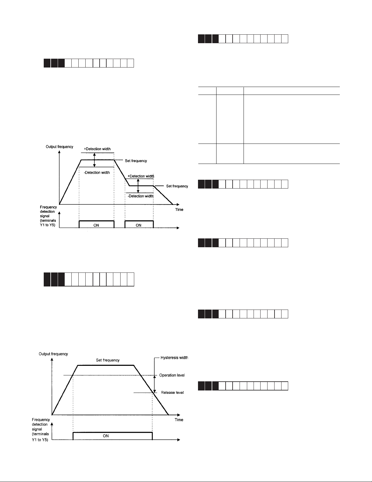
Value Function Description
0
1
When the set value is 1, contacts Y5A and Y5C are
E33 Overload early warning (operation)
connected when the drive control voltage is established
(about one second after power on).
E30 Frequency arrival (detection width)
E33OL LEVEL
Setting range: 0: Electronic thermal O/L relay
Select one of the following two types of overload early
E30FAR HYSTR
Setting range: 0.0 to 10.0 Hz
warning: early warning by electronic thermal O/L relay
function or early warning by output current.
1: Output current
This function adjusts the detection width when the output
frequency is the same as the set operating frequency. The
detection width can be adjusted from 0 to ±10 Hz of the
setting frequency.
When the frequency is within the detection width, an ON
signal can be selected and output from terminals [Y1] to
[Y5]
Electronic
thermal
O/L relay
Overload early warning by electronic thermal
O/L relay (with inverse time characteristics)
to output current. The operation selection and
thermal time constant for the inverse time
characteristics are the same as those of the
electronic thermal O/L relay for motor
protection (F10 and F12).
E31 Frequency detection (operation level)
E32 Frequency detection (hysteresis width)
E31FDT LEVEL
E32FDT HYSTR
Setting range (Operation level): 0 to 120 Hz
These functions determine the operation level of the
output frequency and hysteresis width for operation
release. If the output frequency exceeds the set operation
level, an ON signal can be output from terminals Y1 to Y5.
(Hysteresis width): 0.0 to 30.0 Hz
Output
current
An overload early warning is issued when
output current exceeds the set current value
for the set time.
E34 Overload early warning (operation level)
E34OL1 LEVEL
Setting range: Drive rated output current x (5 to 150%)
This function determines the operation level for the
electronic thermal O/L relay or output current.
The operation release level is 90% of the set value.
E35 Overload early warning (operation time)
E35OL T IMER
Setting range: 0.0 to 60.0 seconds
This function is used when E33 Overload early warning
(operation selection) is set to 1.
Sets the time from when the operation level is attained
until the overload early warning function is activated.
E36 Frequency detection 2 (operation level)
E36FDT 2 LEVEL
This function determines the operation (detection) level 2
of the output frequency for operation release. This
function operates the same as “E31 Frequency detection
1 (operation level)”. For details, see the explanation for
E31.
E37 Overload early warning 2
(operationlevel)
E37OL2 LEVEL
This function determines the operation level 2 of the
output current. This function operates same as E33
output current and E35 setting.
5-25
Page 79

E40 Display coefficient A
E41 Display coefficient B
E40COE F A
E41COE F B
Setting range:
Display coefficient A: -999.00 to 0.00 to +999.00
Display coefficient B: -999.00 to 0.00 to +999.00
These coefficients are conversion coefficients which are
used to determine the load and line speed and the PID
controller target value and feedback (process) amount
displayed on the LED monitor.
Load and line speed
Use display coefficient A.
Displayed value = output frequency x (0.01 to 200.00)
Although the setting range is ±999.00, the effective range
of display data is 0.01 to 200.00. Therefore, values
smaller or larger than this range are limited to a minimum
value of 0.01 or a maximum value of 200.00.
Ta rget value and feedback amount of PID controller
Set the maximum value of display data in E40 Display
coefficient A and the minimum value in E41 Display
coefficient B.
Displayed value = (target value or feedback amount)
x (Display coefficient A - B) + B
Display during running and stopping
During running, the items selected in E43 LED monitor
(display selection) are displayed. In E44 LED monitor
(display at stopping), specify whether to display selected
items or the same items as during running.
Value of
E43
0
1
2
3
4
5
6
7
8
9
10
11
12
at stopping
set
frequency
value (Hz)
set
frequency
value (Hz)
set frequency value (Hz)
output current (A)
output voltage command value (V)
synchronous
speed set
value (rpm)
line speed
set value
(m/min)
set load
speed (rpm)
calculated torque value (%)
output power (kW)
PID target value 1 (direct input from keypad panel)
PID target value 2 (input from F02 Frequency 1)
PID feedback amount
during
running
output frequency after slip
compensation (Hz)
output frequency after slip
compensation (Hz)
synchronous speed (rpm)
line speed (m/min)
load speed (rpm)
at stopping
E44 = 1E44 = 0
during
running
Note: For E43 = 10 to 12, the data is displayed only if
selected in H20 PID control (operation selection).
E42 Display filter
E42DISPLAY FL
Setting range: 0.0 to 5.0 seconds
Among data in E43 LED monitor (display selection), some
Display at frequency setting
When a set frequency is checked or changed by the
keypad panel, the value shown below is displayed.
Select the display item by using E43 LED monitor (display
selection). This display is not affected by E44 LED monitor
(display at stopping).
data need not be displayed instantaneously when the data
changes. For such data, a flicker suppression filter can be
used.
Value of E43 Frequency Setting
Monitored items in E43 LED monitor (display selection)
Value Display Value Display
3 Output current 8 Calculated torque value
4 Output voltage 9 Power consumption
E43 LED monitor (display selection)
E44 LED monitor (display at stopping)
E43LED MNT
E44LED MNT2
The data during drive operation, stopping, at frequency
setting, and at PID setting is displayed on the LED.
Note: For E43 = 10 to 12 the data is displayed only if
selected in H20 PID control (operation selection).
0,1,2,3,4 set value of frequency (Hz)
5 set value of synchronous speed (rpm)
6 set value of line speed (m/min.)
7 set value of load speed (rpm)
8,9 set value of frequency (Hz)
10,11,12 set value of frequency (Hz)
5-26
Page 80

E45 LCD monitor (display selection)
E46 LCD monitor (language)
E45LCD MNTR
This function selects the items to be displayed on the
LCD monitor in operation mode.
Value Display Items
Operation status, direction of rotation,
0
1
operation guide
Output frequency before slip compensation,
output current, calculated torque in bar graph
Set value: 0
During running When stopping
60.00
STOP
PRG PRG
MENU
F/D LED SHIFT
60.00
RUN
FWD
Set value: 1
60.00
E46LANGUAGE
This function selects the language for data display on the
E46
LCD monitor.
Value Language Value Language
0Japanese 3 French
E47
1 English 4 Spanish
2 German 5 Italian
Note: English language is used for all LCD screens in
this manual.
E47 LCD monitor (contrast adjustment)
E47CON TRAS T
This function adjusts the LCD contrast. Increase the set
value to raise contrast and decrease to lower contrast.
Value 0, 1, 2 • • • • • • 8, 9, 10
Screen Low High
Hz
A
%
Fout/Iout/TRQ
Full scale value of bar graph
Display item Full scale
Output frequency Maximum frequency
Output current 200% of drive rated value
Calculated torque value 200% of motor rated value
Note: The scale cannot be adjusted.
5-27
Page 81

C: Control Functions of Frequency
C01 Jump frequency 1
C02 Jump frequency 2
C03 Jump frequency 3
C04 Jump frequency hysteresis
C0 1 JUMP Hz 1
C0 2 JUMP Hz 2
C0 3 JUMP Hz 3
Setting range: 0 to 120 Hz in 1Hz increments (min.)
C0 4JUMP HYSTR
Setting range: 0 to 30 Hz in 1Hz increments (min.)
This function makes the set frequency jump so that the
drive’s output frequency does not match the mechanical
resonance point of the load.
Up to three jump points can be set.
This function is ineffective if jump frequencies 1 to 3 are
set to 0 Hz.
A jump does not occur during acceleration or decelera-
tion.
If a jump frequency setting range overlaps another range,
both ranges are added to determine the actual jump area.
C05-C19 Multi-step frequency 1 to 15
C0 5MUL T I Hz – 1
C0 6MUL T I Hz – 2
C0 7MUL T I Hz – 3
C0 8MUL T I Hz – 4
C0 9MUL T I Hz – 5
C1 0MUL T I Hz – 6
C1 1MUL T I Hz – 7
C1 2MUL T I Hz – 8
C1 3MUL T I Hz – 9
C1 4MUL T I Hz 1 0
C1 5MUL T I Hz 1 1
C1 6MUL T I Hz 1 2
C1 7MUL T I Hz 1 3
C1 8MUL T I Hz 1 4
C1 9MUL T I Hz 1 5
Setting range: 0 to 120 Hz In 0.01 Hz increments (min.)
Multistep frequencies 1 to 15 can be switched by turning
terminal functions SS1, SS2, SS4, and SS8 on and off.
(See E01 to E09 for terminal function definitions.)
OFF is the default value any undefined SS1, SS2, SS4,
and SS8 terminals.
Related functions: E01 to E09 (Set value: 0 to 3)
Output frequency
(Hz)
➝
Jump frequency
width
➝
Output frequency
(Hz)
➝
➝
Actual
jump width
➝
Jump frequency
width
➝
➝
➝
Jump frequency
➝
Jump frequency 1
➝
width
➝
Jump frequency
➝
➝
➝
➝
➝
➝
➝
➝
➝
➝
➝
➝
➝
➝
width
➝
➝
➝
Jump frequency 2
➝
➝
➝
➝
Jump frequency 1
➝
➝
➝
Jump frequency 3
Set frequency (Hz)
➝
➝
Jump frequency 2
➝
Set frequency (Hz)
Output Frequency
➝
➝
➝
➝
➝
➝
(Hz)
FWD-CM
SS1-CM
SS2-CM
SS4-CM
SS8-CM
C05
ON
C06
ON
C07
ON
C08
C09
ON
ON
C10
ON
C11
ON
C13
C12
ON
ON
C14
C15
C16
C17
ON
ON ON
ON ON
ON
ON
C18
C19
5-28
Page 82

C20 Jog frequency
C22-C28 Pattern operation (stage 1 to 7)
C2 0JOG Hz
Setting range: 0.00 to 120.00 Hz
This function sets a frequency for the motor jogging
operation, which is different from the normal operation.
The jogging frequency is used for operation when the
jogging mode signal is received from the keypad panel or
control terminal. For details, see the explanations of
E01 Terminal X1 to E09 Terminal X9.
C21 Pattern operation (operation selection)
C2 1PAT TERN
Pattern operation is an automatic operation according to
a preset operation time, direction of rotation, acceleration and deceleration time, and frequency.
When using this function, set F01 Frequency setting to
10 (pattern operation).
[Related Functions: F01, C30 = 10]
The following operation patterns can be selected.
Value Operation Pattern
0 Perform a pattern operation cycle, then stop
operation.
1 Perform pattern operation repeatedly.
Operation is stopped by the STOP operation.
2 Perform a pattern operation cycle, then
continue operation at the last set frequency.
C2 2STAGE 1
C2 3STAGE 2
C2 4STAGE 3
C2 5STAGE 4
C2 6STAGE 5
C2 7STAGE 6
C2 8STAGE 7
Seven stages are operated in order of function codes,
according to the values set in C22 Pattern operation
(stage 1) to C28 Pattern operation (stage 7). Each
function sets the operation time and the direction of
rotation for each stage and assigns values to acceleration
and deceleration time.
Set or assign item Value range
Operation time 0. 00 to 6000s
Rotation F: Forward (counterclockwise)
direction R: Reverse (clockwise)
Acceleration and 1: Acceleration time 1 (F07)
deceleration time Deceleration time 1 (F08)
2: Acceleration time 2 (E10)
Deceleration time 2 (E11)
3: Acceleration time 3 (E12)
Deceleration time 3 (E13)
4: Acceleration time 4 (E14)
Deceleration time 4 (E15)
Note: The operation time is represented by the three
most significant digits, hence, can be set with
only three high-order digits.
Setting example
100 F 3
Acceleration and deceleration
time (code): 3
Motor rotating direction:
Forward (counterclockwise)
Operation time: 100s
Set the operation time to 0.00 for any unused stages,
which are skipped during operation.
In regard to the set frequency value, the multi-step
frequency function is assigned according to the table
below. Seven frequencies can be set for C05 Multi-step
frequency 1 to C11 Multi-step frequency 7.
Stage No. Operation Frequency
Stage 1 Multi-step frequency 1 (C05)
Stage 2 Multi-step frequency 2 (C06)
Stage 3 Multi-step frequency 3 (C07)
Stage 4 Multi-step frequency 4 (C08)
Stage 5 Multi-step frequency 5 (C09)
Stage 6 Multi-step frequency 6 (C10)
Stage 7 Multi-step frequency 7 (C11)
5-29
Page 83

Pattern operation example
FunctionValue / Operation Frequency
C21 1 Selects function
C22 (stage 1) 60.0F2 Multi-step frequency 1 (C05)
C23 (stage 2) 100F1 Multi-step frequency 2 (C06)
C24 (stage 3) 65.5R4 Multi-step frequency 3 (C07)
C25 (stage 4) 55.0R3 Multi-step frequency 4 (C08)
C26 (stage 5) 50.0F2 Multi-step frequency 5 (C09)
C27 (stage 6) 72.0F4 Multi-step frequency 6 (C10)
C28 (stage 7) 35.0F2 Multi-step frequency 7 (C11)
Notes:
1. The direction of rotation cannot be reversed by a
command issued from the REV key on the keypad
panel or Terminal REV. Any reverse rotation commands entered will be canceled. Select forward or
reverse rotation by the data in each stage. If the
control terminals are used for operation, the self-hold
function will not work. Select an alternate type switch
when using control terminals.
2. At the end of a cycle, the motor decelerates to stop
according to the value set in F08 Deceleration time 1.
C30 Frequency setting 2
The following diagram shows this operation.
C3 0FREQ CMD 2
For the setting method, see the explanation for F01.
Notes: Setting 2, 3, and 7 are inactive. (C1 signals)
This function determines the frequency setting method.
C31 Analog input bias adjustment
The setting range is -100.0 to +100.0% (in 0.1% increments) of the maximum output frequency.
C32 Analog input gain adjustment
The gain adjustment range is 0.0 to 200%.
C3 1BIAS
C3 2GA I N
These functions set the gain and bias for analog input
Terminals 12, in conjunction with functions F17 (freq. gain)
and F18 (freq. bias).
For details, see the explanation for F17 and F18.
C33 Analog setting signal
C3 3REF F I LTER
Running and stopping are controlled by pressing the
STOP or FWD keys or by opening and closing the control
terminals.
When using the keypad panel, the FWD key starts
operation. The STOP key pauses stage advance. Pressing
the FWD key again will restart operation from the stop
point according to the stages. If an alarm stop occurs,
press the RESET key to release the drive protective
function, then press the FWD key to restart stage advance.
If operation is to restart from the first stage, C22 Pattern
operation (stage 1), enter a STOP command and press
the RESET key.
If an alarm stop occurs, press the RESET key to release
the protective function, then press the RESET key again.
5-30
Setting range: 0.00 to 5.00 seconds
Analog signals input from Terminals 12, V2 or C1 may
contain noise which renders the control unstable. This
function adjusts the time constant of the input filter to
remove the effects of noise.
A value that is set too large delays control response
although stabilizing the control. A value that is set too
small speeds up control response but renders the control
unstable.
If the optimum value is not known, adjust the setting if
the control is unstable or response is delayed.
Note:
The set value is commonly applied to Terminals 12, V2
and C1. For input of PID feedback, the PID control
feedback filter (H25) is used.
Page 84

Notes
5-31
Page 85

Motor 1 (P: Motor Parameters)
P01 Number of motor 1 poles
P01M1 POLES
Value Operation
Setting range:: 2, 4, 6, 8, 10, 12, 14
This function sets the number of poles in Motor 1. If this
setting is not made, an incorrect motor speed (synchronous speed) is displayed on the LED.
P02 Motor 1 (capacity)
P02M1–CAP
Set values for models with nominal motor capacity of
30Hp or less: 0.01 to 60Hp
Set values for models with nominal motor capacity of
40Hp or more: 0.01 to 800Hp
The nominal motor capacity is set at the factory. This
setting should only be changed when driving a motor with
a different capacity.
Set the nominal motor capacity listed in 9-1 Standard
Specifications. A value in the range from two ratings lower
to one rating higher than the nominal motor capacity can
be set. If a value outside this range is set, accurate
control cannot be guaranteed. If a value between two
nominal motor capacities is set, data for the lower
capacity is automatically stored for related function data.
If this function setting is changed, the following related
functions are automatically set to data values for the Fuji
3-phase standard motor.
— P03 Motor 1 (rated current)
— P06 Motor 1 (no-load current)
— P07 Motor 1 (% R1)
— P08 Motor 1 (% X1)
Note:
The values for the GE 3-phase standard motor are 230V,
60Hz, 4 poles for the 230V series; 460V, 60Hz, 4 poles for
the 460V series.
P03 Motor 1 (rated current)
P03M1 R
Setting range: 0.00 to 2,000 A
This function sets the rated current value for Motor 1.
-
I
Perform auto tuning if the previously stored data in P06
No-load current, P07 %R1, and P08 %X differs from the
actual motor data. Some typical examples are listed
below. Auto tuning improves control and calculation
accuracy.
– When a motor other than the GE standard 3-phase
– When output-side impedance cannot be ignored, e.g.
– When %R1 or %X is unknown, e.g. when a non-
Tuning Procedure
1. Adjust the voltage and frequency according to motor
2. First enter motor constants that cannot be tuned. Set
3. When tuning the no-load current, beware of motor
4. Set function P04 Auto tuning = 1 (motor stop) or 2
5. Tuning may take several seconds. If P04=2, the motor
6. Press the STOP key, and the procedure will end.
0 Inactive
Measure the motor’s primary resistance (%R1)
and base frequency leakage reactance (%X) when
1
the motor is stopping and automatically store both
values in P07 and P08.
Measure the motor’s primary resistance (%R1)
and base frequency leakage reactance (%X) when
2
the motor is stopping, measure the no-load current
(lo) when the motor is running, and automatically
store these values in P06, P07, and P08.
motor is used, and accurate data is required for close
control.
when the cable between the drive and the motor is
too long or when a reactor is connected.
standard or special motor is used.
data. Adjust functions F03 Maximum output frequency, F04 Base frequency, F05 Rated voltage, and
F06 Maximum output voltage.
functions P02 Capacity, P03 Rated current, and P06
No-load current (no-load current setting is not
required if P04=2).
rotation.
(motor rotation). Press the FUNC/DATA key to store
the set value and press the FWD key or REV key.
Tuning will start.
accelerates up to half the base frequency according
to acceleration time, is tuned for the no-load current,
and decelerates according to the deceleration time.
The total tuning time varies depending on the settings
for acceleration and deceleration time.
P04 Motor 1 (Tuning)
P04M1 TUN1
This function measures and automatically stores motor
data.
Note: Use function A13 Motor 2 (auto tuning) to tune
Motor 2. In this case, the set values described in (1) and
(2) above are for functions A01, etc. corresponding to
Motor 2.
WARNING
If the auto tuning value is set to 2, the motor rotates
at a maximum of half the base frequency. Beware of
motor rotation as injury may result.
5-32
Page 86

P05 Motor 1 (On-line Tuning)
P09 Slip compensation control
P05M1 TUN2
Long-time operation affects motor temperature and motor
speed. On-line tuning minimizes speed changes related
to these temperature changes.
Value Operation
0 Inactive
1 Active
P06 Motor 1 (no-load current)
P06M1– IO
P09SLI P COMP1
Setting range: 0.00 to 15.00 Hz
Changes in load torque affect motor slippage, thus
causing variations in motor speed. The slip compensation
control adds a frequency, proportional to motor torque, to
the drive output frequency. This will minimize variations in
motor speed due to changes in torque.
Calculate the amount of slip compensation using the
following formula:
= Base frequency X
Setting range: 0.00 to 2,000 A
This function sets the no-load current (exciting current) for
Motor 1.
Slippage = Synchronous speed - Rated speed
P07 Motor 1 (%R1 setting)
P08 Motor 1 (%X setting)
P07M1 %R1
P08M1 %X
These functions are used to set data if using a motor
other than the GE standard 3-phase motor and when the
motor constant and the impedance between the drive and
motor are known.
Slippage [r/min.]
Synchronous speed [r/min.]
[Hz]
Calculate %R1 using the following formula:
%R1 =
R1 + CableR
X 100 [%]
V / ( 3 • I )
R1: Primary coil resistance value of the motor [W]
Cable R: Output-side cable resistance value [W]
V: Rated voltage [V] I: Rated current [A]
Rated current
X1 +X2 • XM / (X2+XM) + Cable X
%X =
X 100 [%]
V / ( 3 • I )
X1: Primary leakage reactance of the motor [W]
X2: Secondary leakage reactance (converted to a primary
value) of the motor [W]
XM: Exciting reactance of the motor [W]
Cable X: Output-side cable reactance [W]
V: Rated voltage [V]
I: Rated current [A]
Note:
For reactance, use a value from the data stored in F04
Base frequency 1.
When connecting a reactor or filter to the output circuit,
add its value. Use value 0 for cable values that can be
ignored.
5-33
Page 87

H: High Performance function
H03 Data initializing
H0 3DAT A INIT
Setting rnage: 0: Disabled
1: Initializes data
This function returns all function data changed by the
customer to the
original factory settings (initialization).
To perform initialization, press the STOP and ^ keys
together to set H03=1, then press the FUNC/DATA key.
The values for all functions are initialized. The set value
in H03 automatically returns to 0 following the end of
initialization.
H04 Auto-reset (Times)
H05 Auto-reset (Reset interval)
H0 4AUTO–RESET
H0 5RESET I NT
Set the protective function release count and waiting time
from its startup to release.
Setting range:
(Count) : 0, 1 to 10
(Waiting time) : 2 to 20 seconds
When a drive protective function which invokes the retry
operation is activated, these functions release operation
of the protective function and restarts operation without
issuing an alarm or terminating output.
To disable the retry function, set H04 Retry (count) = 0.
Drive protective functions that can invoke the retry
function:
OC1, OC2, OC3: dBH:
Overcurrent braking resistor overheating
OV1, OV2, OV3: OL1:
Overvoltage Motor 1 overload
OH1: OL2:
Heat sink overheating Motor 2 overload
OH3: OLU:
Drive overheating Drive overload
internally
If the value of H04 Retry (count) is set from 1 to 10, a
drive run command is immediately entered following the
wait time set in H05 Retry (wait time) and the startup of
the retry operation. If the cause of the alarm has been
removed at this time, the drive starts without switching to
alarm mode. If the cause of the alarm still remains, the
protective function is reactivated according to the wait
time set in H05 Retry (waiting time). This operation is
repeated until the cause of the alarm is removed. The
restart operation switches to alarm mode when the retry
count exceeds the value set in H04 Retry (count). The
operation of the retry function can be monitored from
terminals Y1 to Y5.
H06 Fan stop operation
H0 6FAN STOP
Setting range: 0: ON/OFF control disabled
This function specifies whether ON/OFF control for the
cooling fan is automatic. While power is applied to the
drive, the automatic fan control detects the temperature of
the heatsink and turns the fan on or off. When this control
is not selected, the cooling fan rotates continuously.
The cooling fan operating status can be monitored from
terminals Y1 to Y5.
H07 ACC/DEC (Mode select) pattern
H0 7ACC PTN
Setting range: 0: Inactive (linear acceleration and
This function selects the acceleration and deceleration
pattern.
5-34
WARNING
When the retry function is selected, operation will
automatically restart, depending on the cause of
the stop. (The machine should be designed to
ensure safety during a restart.) When the retry
function is selected, GE start software
(F02 set 3 or 4) does not work.
1: ON/OFF control enabled
deceleration)
1: S-shape acceleration and deceleration (mild)
2: S-shape acceleration and deceleration (sharp)
3: Curvilinear acceleration and deceleration
Page 88

S-shape Acceleration and Deceleration
q
This pattern reduces shock by mitigating output frequency
changes at the beginning and end of acceleration and
deceleration.
H09 Start mode
H0 9START MODE
Setting range 0, 1, 2
This function smoothly catches a spinning motor which is
coasting after a momentary power failure or after the
motor has been subject to external force, without stopping the motor, i.e. windmilling fan.
At startup, this function detects the motor speed and
outputs the corresponding frequency, thereby enabling a
shock-free motor startup. The normal startup method is
used if the coasting speed of the motor is 120 Hz or more
as a drive frequency and if the value of F03 Maximum
frequency exceeds the value of F15 Frequency limiter
(upper limit).
Pattern constants>
Range of
S-shaped
Time for
S-shaped at
acceleration
Time for
S-shaped at
deceleration
When 1 is
selcted in H07
(mid S-shape
pattern)
0.05 x maximum
output
fre
uency (Hz)
0.10 x
acceleration
time (s)
0.10 x
deceleration (s)
When 2 is selcted in
H07 (mid S-shape
pattern)
0.10 x maximum output
frequency (Hz)
0.20 x acceleration
time (s)
0.20 x deceleration (s)
*
Explanation
1. This function is effective if F14 Restart after momen-
When acceleration and deceleration times are very long or
short, acceleration and deceleration are almost linear.
Curvilinear Acceleration and Deceleration
2. In addition to restarting following a momentary power
This function is used to minimize motor acceleration and
deceleration times in the range that includes a constant
output range.
Output
frequency
Maximum
output
Set
frequency
Base
frequency
acceleration
deceleration
By assigning 26 (start characteristics selection) to
terminals X1 to X9, this function can be externally
selected as the normal startup method whenever an ON
operation command is entered.
Restart after a
Value
0Inactive Inactive Inactive
1Inactive Active Active
2 Active Active Active
Normal
startup
momentary Line-to-drive
power switching
failure
tary power failure (operation selection) is set to 3, 4,
or 5. This function is also effective when operation is
switched from the line to the drive. The motor is
started with the same frequency as the current
coasting speed (speed search).
failure and switching between the line and the drive,
this function detects the coasting speed of the motor
and starts the motor at the same frequency as all
startups (including when an ON operation command
is entered).
0t [sec]
H08 Rev. phase sequence lock
H0 8REV LOCK
Setting range: 0: Inactive
1: Active
If accidental reversing could result in a malfunction, this
function can be set to prevent reversal.
This function prevents a reversing operation resulting from
a connection between the REV and CM terminals,
inadvertent activation of the REV key, or negative analog
input from Terminals 12 or V1.
Note: The dotted-dashed line indicates motor speed.
5-35
Page 89

H10 Energy-saving operation
H13 Auto-restart (Restart time)
H10ENERGY SAV
Setting range: 0: Inactive 1: Active
With constant-speed operation at light loads (fixed output
frequency), this function automatically reduces the output
voltage while minimizing the product of voltage and
current (power).
[Exception: If F09 Torque boost 1 = 0.0]
Notes:
Use this function for variable torque loads (e.g., fans,
pumps). If used for a constant torque load or rapidly
changing load, this function causes a delay in control
response.
The energy-saving operation automatically stops during
acceleration and deceleration or when the torque limiting
function is activated.
H11 DEC mode
H11DEC MODE
Setting range: 0: Deceleration-to-stop based on data
set with H07 Non-linear acceleration
and deceleration
1: Coasting-to-stop
This function determines the drive stopping method when
a STOP command is entered.
Note:
This function is effective only when a STOP command is
entered and, therefore, is ineffective if the motor is
stopped by lowering the set frequency.
H12 Instantaneous overcurrent limiting
H12 INST CL
Setting range: 0: Inactive 1: Active
An overcurrent trip generally occurs when current flows
above the drive protective level, following a rapid change
in motor load. The instantaneous overcurrent limiting
function controls drive output and prohibits the flow of a
current exceeding the protective level, even if the load
changes.
Since the operation level of the instantaneous overcurrent
limiting function cannot be adjusted, the torque limiting
function must be used.
Motor generation torque may be reduced when instantaneous overcurrent limiting is applied. Set this function to
be inactive for equipment such as elevators, which are
adversely affected by reduced motor generation torque, in
which case an overcurrent trip occurs when the current
flow exceeds the drive protective level. A mechanical
brake should be used to ensure safety.
H13RESTART T
Setting range: 0.1 to 10.0 seconds
Instantaneous switching to another power line (when the
power of an operating motor is cut off or power failure
occurs) creates a large phase difference between the line
voltage and the voltage remaining in the motor, which may
cause electrical or mechanical failure. To rapidly switch
power lines, store the remaining voltage attenuation time
to wait for the voltage remaining in the motor to attenuate.
This function operates at restart after a momentary power
failure.
If the momentary power failure time is shorter than the
wait time value, a restart occurs following the wait time. If
the power failure time is longer than the wait time value, a
restart occurs when the drive is ready to operate (after
about 0.2 to 0.5 seconds).
H14 Auto-restart (freq. fall rate)
H14FALL RATE
Setting range: 0.00, 0.01 to 100.00 Hz/s
If H14 = 0.00, the frequency is reduced according to the
set deceleration time.
This function determines the reduction rate of the output
frequency for synchronizing the drive output frequency
with the motor speed. This function is also used to
reduce the frequency and thereby prevent stalling under a
heavy load during normal operation.
Note:
A frequency reduction rate that is set too large may
temporarily increase the regeneration energy from the load
and invoke the overvoltage protective function. Conversely, a rate that is too small extends the operation time
of the current limiting function and may invoke the drive
overload protective function.
H15 Auto-restart (holding DC voltage)
H15HOLD V
Setting range 230V series: 200 to 300V
This function is used when F14 Restart after momentary
power failure (operation selection) is set to 2 (deceleration-to-stop at power failure) or 3 (operation continuation).
Either function starts a control operation if the main circuit
DC voltage drops below the set operation continuation
level.
If power supply voltage to the drive is high, control can be
stabilized even under an excessive load by raising the
operation continuation level. However, if the level is too
high, this function activates during normal operation and
causes unexpected motion. Please contact GE Fuji
before changing the factory default value.
460 V series: 400 to 600V
5-36
Page 90

H16 Auto-restart (OPR command selfhold time)
H16SELFHOLD T
Setting range: 0.0 to 30.0 seconds, 999
Since the power to an external operation circuit (relay
sequence) and the main power to the drive is generally cut
off at a power failure, the operation command issued to
the drive is also cut off. This function sets the time an
operation command is to be held in the drive. If a power
failure lasts beyond the self-hold time, power-off is
assumed, automatic restart mode is released, and the
drive starts operation at normal mode when power is
applied again. (This time can be considered to be the
allowable power failure time.)
If H16 = 999, an operation command will be held until
control power in the drive is established or until the main
circuit DC voltage is about 0.
H19 Active drive
H19AUT RED
Setting range: 0: Inactive
1: Active
This function automatically extends accelerating time by
60 seconds or longer to prevent an inverter trip resulting
from a temperature rise in the inverter due to overcurrent.
(If the active drive function is activated, the acceleration
time will be three times the selected time.)
H20 PID control (mode select)
H20PID MODE
Setting range: 0: No operation
1: Normal operation
2: Inverse operation
PID control detects the amount of feedback from a sensor
and compares it with the target value (e.g., reference
temperature). If the values differ, this function produces
an output to eliminate the deviation. In other words, this
control matches the feedback amount with the target
value.
This function can be used for flow control, pressure
control, temperature control, and other process controls.
Forward or reverse operations can be selected for PID
controller output. This enables motor revolutions to be
faster or slower according to PID controller output.
5-37
Page 91

The target value can be entered using F01, Frequency
setting 1, or directly from the keypad panel.
For entry from F01, Frequency setting 1, input a signal to
the selected terminal. For direct entry from the keypad
panel, turn on keypad operation. Select any of the digital
Terminals X1 (E01) to X9 (E09) and assign a value of 11
Only positive values can be input for this feedback
amount of PID control. Negative values (e.g., 0 to -10V, 10 to 0V) cannot be input, thereby the function cannot be
used for a reverse operation by an analog signal.
Feedback signal setting (H21) must be different from the
type of setpoint value.
(frequency setting switching).
NOTE: For the target value and feedback amount, the
process amount can be displayed according to the values
set in E40 Display coefficient A, and E41 Display coefficient B.
H21 PID control (feedback signal)
H21FB SIGNAL
This function selects the terminal, direction of operation,
and feedback input. Select a value from the table below
according to sensor specifications.
Value Description
0 Terminal 12, forward operation, 0 to 10V voltage input
1 Terminal C1, forward operation, 4 to 20mA current input
2 Terminal 12, reverse operation, 10 to 0V voltage input
3 Terminal C1, reverse operation, 20 to 4mA current input
5-38
Page 92

H22 PID control (P-gain)
H23 PID control (I-gain)
H24 PID control (D-gain)
These functions are not generally used alone but are
combined like P control, PI control, PD control, and PID
control.
P-gain operation
An operation using an output frequency proportional to
deviation is called P operation, which outputs an
operation amount proportional to deviation, though it
cannot eliminate deviation alone.
H22P–GAIN
Setting range: 0.01 to 10.0 times
P (gain) is the parameter that determines the response
level for the deviation of P operation. Although an
increase in gain speeds up response, an excessive gain
causes vibration, and a decrease in gain delays response.
I-gain operation
An operation where the change speed of the output
frequency is proportional to the deviation is called an I
operation. An I operation outputs an operation amount as
the integral of deviation and, therefore, has the effect of
matching the feedback control amount to the target value
(e.g., set frequency), though it deteriorates response for
significant changes in deviation.
5-39
Page 93

H23 I–GAIN
Setting range: 0.0 (Inactive), 0.1 to 3600 seconds
H23 I-gain is used as a parameter to determine the
effect of I operation. A longer integration time delays
response and weakens resistance to external elements.
A shorter integration time speeds up response, but an
integration time that is too short causes vibration.
D-gain operation
An operation where the output frequency is proportional
to the deviation differential is called a D operation. It
outputs an operation amount as the deviation differential
and, therefore, is capable of responding to sudden
changes.
H24D–GAIN
PID control
PID control combines the P operation, the I operation
which removes deviation, and the D operation which
suppresses vibration. This control achieves deviationfree, accurate, and stable responses.
Adjusting PID value
Adjust the PID value while monitoring the response
waveform on an oscilloscope or other instrument, if
possible. Proceed as follows:
Increase the value of H22 P-gain without generating
vibration.
Decrease the value of H23 I-gain without generating
vibration.
Increase the value of H24 D-gain without generating
vibration.
Adjust the response waveform as follows:
To remove the overshoot, increase the value of H23 I-gain,
then decrease the value of H24 D-gain.
Setting range: 0.00 (Inactive), 0.01 to 10.0 seconds
H24 D-gain is used as a parameter to determine the
effect of a D operation. A longer differentiation time
causes vibration by P operation quickly attenuating at
the occurrence of deviation. Excessive differentiation
To stabilize response quickly, allowing for min. overshoot,
decrease the value of H23 I-gain or increase the value of
H24 D-gain.
time could cause vibration. Shortening the differentiation time reduces attenuation at the occurrence of
deviation.
PI control
P operation alone does not remove deviation completely.
P + I control (where I operation is added to P operation)
is normally used to remove the remaining deviation. PI
control always operates to eliminate deviation, even
when the target value is changed or there is a constant
disturbance. When I operation is strengthened, however,
To suppress vibration with a period longer than the value
of H23 I-gain, increase the value of H23.
the response for rapidly changing deviation deteriorates.
P operation can also be used individually for loads
containing an integral element.
PD control
If deviation occurs under PD control, an output frequency larger than that of D operation alone occurs
rapidly and prevents the deviation from expanding. For
a small deviation, P operation is restricted. When the
load contains an integral element, P operation alone may
allow responses to vibrate due to the effect of the
integral element, in which case PD control is used to
attenuate the vibration of P operation and stabilize
To suppress vibration with a frequency roughly equivalent
to the value H24 D-gain, decrease the value of H24. If
there is residual vibration with 0.0, decrease the value of
H22 P-gain.
responses. In other words, this control is applied to
loads in processes without a braking function.
5-40
Page 94

H25 PID control (Feedback filter)
H25FB FI LTER
Setting range: 0.0 to 60.0 seconds
This filter is for feedback signal input from Terminals 12 or
C1. This filter stabilizes operation of the PID control
system. A set value that is too large, however, deteriorates response.
H26 PTC thermistor (mode select)
H26PTC MODE
Setting range: 0: Inactive
1: Active
Set this function active when the motor has a PTC
thermistor for overheat protection
Connect the PTC thermistor as shown in the figure below.
Turn on switch PTC on the control PCB. The trip mode is
activated by OH2: External thermal relay tripped.
The figure above for H26 PTC thermistor (Mode select)
shows that a 250W resistor and the thermistor (resistance
value Rp) are connected in parallel. Hence, voltage Vc1 at
Terminal C1 can be calculated using the following formula:
250 • Rp
1000+
Rp
250 + Rp
250 • Rp
250 + Rp
1
+ Rp
Rp
2
2
X 10 [V]
[Ohm]
Vc1
The operation level can be set by bringing Rp in the Vc1
calculation formula into the following range.
Rp1 < Rp < Rp2
To calculate Rp, use the following formula:
Note: Must be 0 setting when using 4-20mA reference or
feedback signal and the PTC switch must be off.
H27 PTC thermistor (level select)
H27PTC LEVEL
Setting range: 0.00 to 5.00V
The voltage input to Terminal C1 is compared to the set
voltage level. If the input voltage is equal to or greater
than the set voltage, H26 PTC thermistor (Mode select)
starts.
The PTC thermistor has its own alarm temperature. The
internal resistance value of the thermistor largely changes
at the alarm temperature. The operation voltage level is
set using this change in the resistance value.
5-41
Page 95

H30 Serial link (Function select)
H30LINK FUNC
Setting range: 0 to 3
The link function (communication) provides a standard
RS485 serial interface and optional fieldbus connections.
The serial link function includes:
1) Monitoring (data monitoring, function data check)
2) Frequency setting
3) Operation command (FWD, REV, and other commands for digital input)
4) Write function data
Communication can be enabled and disabled by a digital
input. This function sets the serial link function when
communication is enabled.
H33TIMER
Setting range: 0 to 60.0 sec.
This function sets the error processing timer value.
H34BAUD RATE
Value Processing at Communication Error
0 Immediate Er 8 trip (forced stop)
Continue operation within timer time, Er 8 trip after
1
2
3
time expires
Continue operation and retry within timer time, then
invoke an Er 8 trip if a communication error occurs.
If an error does not occur, continue operation.
Continue operation.
Value
0 Disabled Disabled
1 Enabled Disabled
2 Disabled Enabled
3 Enabled Enabled
Frequency Operation
Command Command
Setting range: 0 to 3
This function sets the baud rate.
The data monitoring and write functions are always
enabled. Disabling communication by a digital input
produces the same results as if this function were set to 0.
If the bus option is installed, this setting selects the bus
function, and the RS485 interface is restricted to monitor-
H35LENGTH
ing and writing function data. If the bus option is not
installed, this setting selects the RS485 function.
This function sets data length.
H31 RS485 (Address)
H39 RS485 (Response interval)
These functions set the conditions for RS485 RTU serial
communication. Set the conditions according to the host
device.
H31ADDRESS
Setting range: 1 to 247
This function sets the station address of RTU.
Maximum connected devices is 31 for an RS-485 network.
H32MODE ON ER
Setting range: 0 to 3
These functions configure the drive behavior in the event
of a communication error.
.
H36PAR ITY
This function sets the parity bit
.
H37STOP BI TS
Value Baud Rate
0 19200 bits/s
1 9600 bits/s
2 4800 bits/s
3 2400 bits/s
Value Data Length
08 bit
Value Parity Bit
0 None
1 Even
2 Odd
This function sets the stop bit
Value Stop Bit
02 bits
11 bit
The stop bit is automatically configured by the value of the
parity bit. For parity “NONE” the stop bit is 2 bits. For
parity “EVEN” or “ODD” the stop bit is 1 bit.
5-42
Page 96

H38NO RES T
Setting range: 0 (no detection)
1 to 60 seconds
In a system where the drive is continuously polled within a
specific time, this function detects that access was
stopped due to an open circuit or other network fault and
results in an Er 8 trip.
H39 INTERVAL
Setting range: 0.00 to 1.00 second
This function sets the time from when a request is issued
from the host device to when a response is returned.
5-43
Page 97

A: Alternative Motor Parameters ( Motor 2 )
A01 Maximum frequency 2
A01MAX Hz – 2
A06 Electronic thermal relay 2 (select)
A07 Electronic thermal relay 2 (level)
A08 Electronic thermal relay 2 (Thermal time
This function sets the maximum frequency for Motor 2
output by the drive. It operates the same as F03 Maximum frequency 1. For details, see the explanation for
F03.
constant)
A02 Base frequency 2
A02BASE Hz –2
This function sets the maximum output frequency in the
constant torque area for Motor 2 (i.e., output frequency at
rated output voltage). It operates the same as F04 Base
frequency 1. For details, see the explanation for F04.
These functions set the function of the electronic thermal
overload relay for Motor 2. They operate the same as F10
to F12 Electronic thermal overload relay 1. For details,
see the explanations for F10 to F12.
A09 Torque vector control 2
A03 Rated Voltage 2
A03RATED V2
This function sets the rated voltage output to Motor 2. It
operates the same as F05 Rated voltage 1. For details,
see the explanation for F05.
This function sets the torque vector function for Motor 2.
It operates the same as F42 Torque vector control 1. For
details, see the explanation for F42.
A10 Number of motor-2 poles
A06ELCTRN OL2
A07OL LEVEL2
A08TIME CNST2
A09TRQVECTOR2
A04 Maximum Voltage 2
A04MAX V– 2
This function sets the maximum drive output voltage for
Motor 2. It operates the same as F06 Maximum voltage 1.
For details, see the explanation for F06.
A05 Torque boost 2
A05TRQ BOOST2
This function sets the torque boost function for Motor 2. It
operates the same as F09 Torque boost 1. For details,
see the explanation for F09.
A10M2 POLES
This function sets the number of poles to be driven by
Motor 2. It operates the same as P01 Number of Motor 1
poles. For details, see the explanation for P01.
A11 Motor 2 (capacity)
A11M2–CAP
This function sets the capacity of Motor 2. It operates the
same as P02 Motor 1 (Capacity). For details, see the
explanation for P02. However, the related motor data
functions change to A12 Motor 2 (Rated current), A15
Motor 2 (No-load current), A16 Motor 2 (%R1 setting), and
A17 Motor 2 (%X setting).
A12 Motor 2 (Rated current)
A12M2– LR
This function sets the rated current for Motor 2. It
operates the same as P03 Motor 1 (Rated current). For
details, see the explanation for P03.
5-44
Page 98

A13 Motor 2 (Tuning)
A13M2 TUN1
This function sets online tuning for Motor 2. It operates
the same as for P04 Motor 1 (Tuning). For details, see the
explanation for P04.
A14 Motor 2 (On-line tuning)
A14M2 TUN2
This function sets online tuning for Motor 2. It operates
the same as P05 Motor 1 (On-line tuning). For details, see
the explanation for P05.
A15 Motor 2 (No-load current)
A15M2 IO
This function sets the no-load current for Motor 2. It
operates the same as P06 Motor 1 (No-load current). For
details, see the explanation for P06.
A16 Motor 2 (%R1 setting)
A17 Motor 2 (%X setting)
A16M2–%R1
A17M2–%X
These functions set %R1 and %X for Motor 2. It operates
the same as P07 Motor 1 (%R1 setting) and P08 Motor 1
(%X setting). For details, see the explanations for P07 and
P08.
A18 Slip compensation control 2
A18SLI P COMP2
This function sets the amount of slip compensation for
Motor 2. It operates the same as P09 Slip compensation
control. For details, see the explanation for P09.
5-45
Page 99

Notes
5-46
Page 100

6. Protective Operations
LED LCD
OC1 OC DURING ACC During acceleration
OC2 OC DURING DEC During deceleration
OC3 OC AT SET SPD
p
Ground fault EF GROUND FAULT
p
Undervoltage LU UNDERVOLTAGE
Input phase loss Lin PHASE LOSS
OH1 FIN OVERHEAT
External alarm OH2 EXT ALARM
OH3 HIGH AMB TEMP
dbH DBR OVERHEAT
Motor 1 overload OL1 MOTOR1 OL
Motor 2 overload OL2 MOTOR2 OL
Drive overload OLU INVERTER OL
Blown fuse FUS DC FUSE OPEN
Memory error Er1 MEMORY ERROR
Er2 KEYPD COM ERR
CPU error Er3 CPU ERROR
Option error Er4 OPTN COM ERR
Er5 OPTION ERROR
Operating error Er6 OPR PROCD ERR
Output wiring error Er7 TUNING ERROR
Modbus RTU error Er8 RS485 COM ERR
p
yp
y
6.1 List of Protective Functions
In the event of an abnormality in the inverter’s operation, the protective function will activate immediately to trip the
inverter and display the alarm name on the LED monitor while the motor coasts to a stop. A list of the alarms with their
explanations is included in the table below, and troubleshooting charts in Section 7.
Table 6.1.1 List of Alarms and Causes
Ke
Alarm Name
Overcurrent
Overvoltage
OU1
OU2
OU3
ad Panel Displa
OV DURING ACC
OV DURING DEC
OV AT SET SPD
If the inverter output current momentarily exceeds the overcurrent detection
Running at constant
eed
s
If a ground fault in the inverter output circuit is detected, the protective function is activated (for 40 Hp
or more only). If a ground fault occurs in an inverter rated at 30 Hp or less, the inverter is protected by
the overcurrent protection. If protection against personal injury or property damage is required, install
a separate ground-fault protective relay or ground leakage circuit breaker.
During acceleration
During deceleration
Running at constant
eed
s
If the DC link voltage in the main circuit falls below the undervoltage detection level (230V series: 400V
DC, 460V series: 800V DC) due to a lowered power supply, the output is shut down. If function F14
Restart after momentary power failure was selected, an alarm is not displayed. In addition, if the supply
voltage falls to a level unable to maintain control power, an alarm may not be displayed.
level, due to an overcurrent in the motor, or a short-circuit or ground fault in the
output circuit, the protective function is activated during heavy load.
If the DC link voltage in the main circuit exceeds the overvoltage detection level
(230V series: 400V DC, 460V series: 800V DC), due to an increase in the
regenerating current from the motor, the output is shut down. However,
protection against inadvertent overvoltage (e.g., high-voltage line) may not be
provided
Cause of Activation
Overheating of heat
sink
Overheating
internally
Overheating of
braking resistor
Keypad panel
communication
error
If input power L1/R, L2/S and L3/T has any phase of the 3 phase power "OPEN" or if there is a significant
disparity between the phases, the retifying diodes or smoothing capacitors may be damaged. An Alarm
is displayed and the protective function is activated during heavy load.
If the temperature of the heat sink rises due to a cooling fan failure, or the temperature of the heatsink
is too low, the protective function is activated during heavy load.
If the external alarm contacts on the braking unit, braking resistor, or external thermal O/L relay are
connected to the control circuit terminals (THR), the contacts will be actuated according to contact
signals.
If the temperature inside the inverter rises due to poor ventilation, etc., the protective function is
activated.
If electronic thermal O/L relay (for braking resistor) function F13 is selected, the protective function is
activated to prevent the resistor from burning due to overheating caused by frequent use of the braking
resistor.
The protective function is activated if the motor current exceeds the preset level, provided that
electronic thermal O/L relay 1 function F10 has been selected.
If the second motor current exceeds the preset level when the operation is switched to drive the
second motor, the protective function is activated, provided that electronic thermal O/L relay 2 of
function A04 was selected.
If the output current exceeds the rated overload current, the protective function is activated to provide
thermal protection against overheating of the semiconductor elements in the inverter’s main circuit.
If the fuse in the inverter is blown out following a short-circuit or damage to the internal circuit, the
protective function is activated (for 40 Hp or more only).
If a memory error occurs, such as missing or invalid data, the protective function is activated.
If a communication error or interrupt between the keypad panel and control circuit is detected, the
protective function is activated.
If a CPU error occurs due to noise, etc., the
Error occurred while using an optional unit.
rotective function is activated.
Note: Number in fron of Alarm Code indicates multiple alarms. See page 4-15.
Data subject to change without notice 7/07. © 2007 GE Drives
Detects drive operating procedure error during drive startup. FWD or REV connected to terminal CM
when Main power is applied to drive (F02 setting 3 or 4). Stop key on keypad is pressed in terminal
operation (F02 setting 1 or 3). Detected timed alarm stop command.
If there is an open circuit or connection error in the inverter output wiring during an auto-tuning
procedure, the protective function is activated.
If an error occurs while using Modbus-RTU, the protective function is activated.
6-1
 Loading...