

Page 1
AF-300E$
1/2 - 350 Horsepower
Instructions
TM
Page 2

General Information – AF-300E$™ Instructions
These instructions do not purport to cover all details or
variations in equipment, nor to provide for every possible
contingency to be met during installation, operation, and
maintenance. Should further information be desired or
should particular problems arise that are not covered
sufficiently for the purchaser's purpose, the matter should
be referred to GE Fuji, Technical Service.
NOTE: The terms "inverter", "controller", and "drive" are
sometimes used interchangably throughout the industry.
We will use the term "Drive" in this document.
AF-300E$™ and X$D™ are trademarks of the General
Electric Company.
®
Energy $aver
Electric Company.
NOTE: Always read the complete instructions prior to
applying power or troubleshooting the equipment and
follow all procedures step by step.
SHOCK HAZARD labels may be located on or inside the
Drive to alert people that dangerous voltage may be
present.
is a registered trademark of the General
WARNING, CAUTION AND NOTES
The following format is used on the equipment or found in
this manual. Read all labels and follow the directions on
them whenever working on the equipment.
WARNING: Denotes operating procedures and practices
that may result in personal injury or loss of life if not
correctly followed.
CAUTION: Denotes operating procedures and practices
that, if not strictly observed, may result in damage to, or
destruction of the equipment.
NOTE: Notes call attention to information that is especially
significant in understanding and operating the equipment.
WARNING, CAUTION AND NOTE PARAGRAPHS
WITHIN THIS INSTRUCTION
The above paragraphs list some general safety reminders
and safety recommendations to be followed when operating or installing this equipment. These safety precautions
will be repeated throughout this instruction book where
applicable.
Copyright © 1998 by General Electric Company, USA.
i
Page 3

Table of Contents
1. SAFETY PRECAUTIONS .......................................................... 1-1
2. DESCRIPTION, COMPONENT IDENTIFICATION,
AND SPECIFICATIONS ................................................................ 2-1
General Description ......................................................................... 2-1
Upon Delivery Inspection Procedures .............................................. 2-2
Drive Keypad Functions and Layout ................................................ 2-3
Table 1: AF-300E$ - Standard Specifications .................................. 2-3
Model Numbering System Diagram ................................................. 2-7
Table 2: AF-300E$ - Drive Dimensions ............................................ 2-8
CE Labeled Products ...................................................................... 2-9
Table 3: AF-300E$ - Drive Ratings, Efficiencies and Watts Loss .... 2-10
3. INSTALLATION GUIDELINES .................................................. 3-1
Installation Environment................................................................... 3-1
Installation Mounting Clearance ....................................................... 3-2
AF-300E$ Dimension Drawings ....................................................... 3-3
4. WIRING PROCEDURES ........................................................... 4-1
Remove Terminal Block Cover ......................................................... 4-1
Control Circuit Wiring ...................................................................... 4-2
Main Circuit Wiring .......................................................................... 4-3
Table 4: AF-300E$ - Drive Cable Size Recommendations and Circuit
Protection Rating ............................................................................ 4-4
Figure 4-5: AF-300E$ - 1/2 to 30 Hp Connection Diagram ............. 4-7
Figure 4-6: AF-300E$ - 40 to 300 Hp Connection Diagram ............ 4-8
Table 5: AF-300E$ - Terminal Identification/Function ....................... 4-9
Auxiliary Control Power Supply Connection ................................... 4-11
DC Link Reactor Connection ......................................................... 4-12
Automatic Restart Circuit Connection............................................ 4-14
Drive Interface Details .................................................................... 4-15
Main Circuit Wiring for CE Mark .................................................... 4-16
Dynamic Braking Technical Information ......................................... 4-17
5. INVERTER OPERATION ........................................................... 5-1
Pre-Operation Inspection ................................................................ 5-1
Keypad Panel Identification/Operation ............................................. 5-1
Function Code and Data Code Description/Selection ......................5-1
Keypad and Display Operation Programming .................................. 5-2
Program Mode - Example of Changing a Function Code ................. 5-3
Program Mode - Example of Checking Function Codes .................. 5-4
Program Mode - Checking Input/Output Signals ............................. 5-5
Keypad Fault Indication ................................................................... 5-6
Display at a Fault ............................................................................. 5-8
Accessing Fault History ................................................................... 5-9
Table 7: Function Code Settings .................................................... 5-10
`6. FUNCTION CODE DESCRIPTIONS ........................................ 6-1
Basic Function ................................................................................ 6-1
Input Terminal Functions ............................................................... 6-13
ACCEL/DECEL Times ................................................................... 6-15
Motor #2 ....................................................................................... 6-16
Analog Monitor Output .................................................................. 6-17
Output Terminals ........................................................................... 6-18
Output Terminal Functions ............................................................. 6-20
Frequency Control......................................................................... 6-22
LED & LCD Monitor ....................................................................... 6-24
Pattern Operation .......................................................................... 6-26
Special Functions .......................................................................... 6-31
Motor Characteristics .................................................................... 6-33
Special Functions (Data Protection) ............................................... 6-34
7. MAINTENANCE AND INSPECTION ........................................ 7-1
Megger Test .................................................................................... 7-1
Periodic Parts Replacement ............................................................ 7-1
Inspection Items .............................................................................. 7-1
Measurement Points and Meters ..................................................... 7-2
8.TROUBLESHOOTING ................................................................ 8-1
Fault Condition Description and Operation ...................................... 8-1
Fault Condition Display and Corrective Actions ............................... 8-2
(1) Overcurrent ................................................................................ 8-9
(2) Ground Fault .............................................................................. 8-9
(3) Overvoltage .............................................................................. 8-10
(4) Undervoltage ............................................................................ 8-11
(5) Inverter Overheat ...................................................................... 8-12
(6) External Failure ......................................................................... 8-12
(7) Overload .................................................................................. 8-13
(8) DC Link Fuse Blown ................................................................. 8-13
(9) Memory Error, Keypad Communication, CPU Error .................. 8-14
(10) Timing Error ........................................................................... 8-14
(11) Motor Will Not Run ................................................................. 8-15
(12) Motor Will Run But Speed Will Not Change ............................ 8-16
(13) Motor Will Stall During Acceleration ........................................ 8-17
(14) Motor Heating Abnormal ........................................................ 8-17
Control Block Diagram .................................................................. 8-18
9. WARRANTY PARTS AND SERVICE ........................................ 9-1
Warranty Coverage ......................................................................... 9-1
Out-Of-Warranty Procedures ........................................................... 9-1
Motors ............................................................................................ 9-1
In Warranty Failure Check List
(Data necessary for Warranty Administration) .................................. 9-2
10. REPLACEMENT PARTS ....................................................... 10-1
11. GLOSSARY - DRIVES TERMINOLOGY ............................... 11-1
12. ELECTROMAGNETIC COMPATIBILITY .............................. 12-1
(1) General .................................................................................... 12-1
(2) RFI Filters ................................................................................. 12-2
(3) Recommened Installation Instructions ...................................... 12-3
ii
Page 4

Section 1: Safety Precautions
WARNING - MECHANICAL MOTION HAZARD:
Drive systems cause mechanical motion. It is the responsibility of the user to insure that any such motion does not
result in an unsafe condition. Factory provided interlocks
and operating limits should not be bypassed or modified.
WARNING - ELECTRICAL SHOCK AND BURN
HAZARD:
When using instruments such as oscilloscopes to work on
live equipment, the oscilloscope’s chassis should be
grounded and a differential amplifier input should be used.
Care should be used in the selection of probes and leads
and in the adjustment of the oscilloscope so that accurate
readings may be made. See instrument manufacturer’s
instruction book for proper operation and adjustments to
the instrument.
WARNING - FIRE AND EXPLOSION HAZARD:
Fires or explosions might result from mounting drives in
hazardous areas such as locations where flammable or
combustible vapors or dusts are present. Drives should be
installed away from hazardous areas, even if used with
motors suitable for use in these locations.
WARNING - STRAIN HAZARD:
WARNING -
Before disassembling, disconnect and lock out power from
the drive. Failure to disconnect power may result in death
or serious injury. A bus charge light provides visual
indication that bus voltage is present; verify the bus voltage
level by measuring the voltage between power terminals
P(+) and N(-) using an analog meter. Do not attempt to
service the drive until the charge indicator has extinguished
and the bus voltage has discharged to zero volts.
WARNING -
Replace all covers before applying power to the drive.
Failure to do so may result in death or serious injury.
CAUTION:
Do not connect power supply voltage that exceeds the
standard specification voltage fluctuation permissible. If
excessive voltage is applied to the drive, damage to the
internal components will result.
CAUTION:
Do not connect power supply to the output terminals (U, V,
W). Connect power supply only to the power terminals (L1,
L2, L3).
Improper lifting practices can cause serious or fatal injury.
Lift only with adequate equipment and trained personnel.
WARNING - ELECTRICAL SHOCK HAZARD:
All motor bases and equipment enclosure housings should
be grounded in accordance with the National Electric Code
or equivalent.
WARNING - MOTOR OVERSPEED HAZARD:
With 400 Hz drive output possible, the drive will allow the
motor to run up to 6 - 7 times its base speed. Never
operate the motor above its top mechanical speed or a
catastrophic failure may occur.
Any applications requiring operation above
120 Hz must be approved by the Company.
CAUTION:
Even though the main AF-300E$ power has been disconnected it may still receive electrical energy from more than
one source. If external power is applied to the control
terminals 30A, B & C and AX1 and AX2 as well as any
option card control input terminal points (if installed in the
drive), and if the independent power source is activated
separately from the AF-300E$'s main input power, failure to
to diconnect this external power source may result in death
or serious injury. This external power must be removed
prior to any work being performed on the drive.
WARNING: this equipment may receive electrical
energy from more than one source. Additional
disconnects are located outside this cabinet. Open all
associated disconnects before servicing equipment.
Refer to equipment diagrams.
1-1
Page 5

CAUTION:
For RUN and STOP, use the FWD-CM (forward) and REVCM (reverse) terminals. Do not use a contactor (ON/OFF)
installed on the line side of the drive for RUN and STOP.
CAUTION:
Because the ambient temperature greatly affects drive life
and reliability, do not install the drive in any location that
exceeds the allowable temperature. Leave the ventilation
cover attached for temperatures of 40 degrees C or below,
CAUTION:
Do not use a switch on the output side of the drive for ON/
OFF operation.
and remove the cover for temperatures of between 40
(104° F) and 50 (122° F) degrees C (30 Hp and lower).
If the cover needs to be removed, another type of
enclosure may be required for safety purposes.
CAUTION: Do not connect filter capacitors on the output
side of the drive.
CAUTION:
If the Drive’s Fault Alarm is activated, consult the
CAUTION:
Do not operate the drive without the ground wire connected. The motor chassis should be grounded to earth
TROUBLESHOOTING section of this instruction book, and
after correcting the problem, resume operation. Do not
reset the alarm automatically by external sequence, etc.
through a ground lead separate from all other equipment
ground leads to prevent noise coupling.
The grounding connector shall be sized in accordance with
the NEC or Canadian Electrical Code. The connection shall
be made by a UL listed or CSA certified closed-loop
terminal connector sized for the wire gauge involved. The
connector is to be fixed using the crimp tool specified by
CAUTION:
Be sure to remove the desicant dryer packet(s) when
unpacking the drive. (If not removed these packets may
become lodged in the fan or air passages and cause the
drive to overheat.)
the connector manufacturer.
CAUTION:
CAUTION:
Do not perform a megger test between the drive terminals
or on the control circuit terminals.
AC induction motors require that they be sized based on
the applications speed range and associated torque
requirements for the motor-drive system. This is to avoid
excessive motor heating. Observe motor manufacturers
recommendations when operating any ac induction motor
CAUTION:
The AF-300E$ drive develops an adjustable frequency via
pulse width modulation, with the pulse rise time of 0.1
with the drive. Also observe motor manufacturer's
recommended voltage/torque boost at lower operating
frequencies.
microseconds. While this does not present a problem on
200-230Vac applications, it may on 380-460Vac applications. When using the AF-300E$ drives on 380-460Vac,
where the distance between the motor and the drive
exceeds 60 feet, get the motor manufacturer's approval
that his insulation system can withstand the voltage spikes
(up to twice the dc bus voltage 2 x 621Vdc for a 460Vac
power source) of the drive, in conjunction with the long
CAUTION:
The available power source connected to the drive is not to
exceed 500KVA. If the ac power source is greater than
500KVA and the driver's rating (Hp) is less than 10% of the
power source's KVA; ac line reactors will have to be
installed in L1, L2 & L3 power leads of the drive.
motor cable lengths. If the insulation system does not meet
this limit, utilize a filter to increase the Drive's pulse rise time
to 1.0 microseconds.
CAUTION:
The drive must be mounted on a wall that is constructed of
heat resistant material. While the drive is operating, the
temperature of the drive's cooling fins can rise to a
temperature of 90°C (194°F. )
1-2
Page 6
Section 2: Description, Component Identication and Specifications
The AF-300E$ drive is available in ratings of 0.5 to 30 Hp
200-230 VAC, 1 to 300 Hp (350Hp variable torque) 380-460
VAC. The AF-300E$ drive incorporates multiple control al-
INSPECTION PROCEDURES UPON DELIVERY
Upon receipt of your drive, inspect the equipment for the
gorithms with either the traditional PWM Scalar power control or a selectable torque vector algorithm with a self tuning
1. Check the nameplate to insure that the specifications
drive/motor function that is used in high performance operation. The AF-300E$ Drives are housed in a NEMA 1 type
2. Inspect the unit for any damage that may have occurred
enclosure for either open or panel mounting and all Inverters
are furnished with a detachable wiring lead-in plate to allow
ease of accessing control and power wiring.
Drive operation and Function Code setting is performed from
the “Keypad Panel” that also features a Digital Monitor, LCD
Graphic Display and 8 dual function keys. The 8 dual function keys are used for drive programming and operation as
well as selection of drive local/remote operation.
General data and specification for each drive are listed on
the nameplate attached to the drive. Refer to TABLE 1 for
complete AF-300E$ drive specification listing.
following items:
correspond to those ordered.
during shipment.
If shipping damage is found or the wrong Inverter is
received, contact the distributor from which this
equipment was purchased.
AF-300E$
MODEL NO.
SERIAL NO.
INPUT:
VOLTS
AMPS
FREQ (HZ)
PHASE (S)
INSTRUCTION
BOOK GEI-100211
All models are UL Listed and CSA Approved*
(Nameplate shown larger than actual size.)
Figure 2-1. NAMEPLATE DATA IDENTIFICATION
* CE Mark for three-phase (3ø), 415 VAC, 1 to 30 Hp only.
CONSTANT
TQ OUTPUT:
VOLTS
FREQ RANGE (HZ)
HP
AMPS CONT.
PHASE
ROTATION
MAX 60 SEC. AMPS
GE Fuji Drives America Made in Mexico
TM
VARIABLE
TQ OUTPUT:
2-1
Page 7
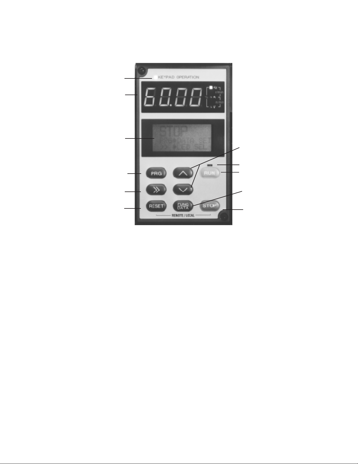
Drive Keypad Functions and Layout
Indication of keypad panel operation
Digital Monitor (4-digit)
LCD Graphic Display
Program Key
Shift Key
Reset Key
Figure 2-2. KEYPAD PANEL COMPONENT IDENTIFICATION
Attachment Screws -The Keypad Panel can be easily
removed from the Drive unit by loosening the two attachment screws. With the optional extension cable, remote
Keypad operation and display is possible.
LCD Graphic Display - LCD Display shows control status or Function Code settings.
PROGRAM (PRG) Key - Operation Mode or Program Mode
selection key.
SHIFT (>>) Key - Changes the digital monitor display in
the Operation Mode. Will also change the LCD graphic
display in Program Mode and Trip Mode.
Unit displayed
}
Up - Down Keys
Run Light
Run Key
Function/Data Key
Stop Key
RUN Key - This key is the RUN command in Keypad operation, run light will be illuminated at this time.
STOP Key - This key is used for stopping operation. If
pressed when the Drive is running by external control, fault
Er6 will be displayed and Drive will coast to a stop.
UP - DOWN Keys - These keys increase or decrease the
frequency (or speed) of the Drive. When unit is in Program
Setting Mode, they change the Function Code or Data Code
values.
LCD Brightness - Function Code 79 permits adjustment
for easy to read brightness of the graphic display.
SET FUND/DATA Key - Displays data setting of selected
Function Codes. Also, stores any changes in software.
RESET Key - After removal of the fault condition, faults
can be reset and will return the Drive to the Operation Mode.
Remote/Local Operation - Remote/Local operation can
be toggled by pressing the RESET and STOP keys simultaneously when the Drive is stopped.
2-2
Unit Display - The unit information is displayed by LEDs
during RUN or STOP condition.
Digital Monitor - Displays Hz, Volts, R/Min, M/Min, or %
as set by the operator using the SHIFT (>>) key or resetting
Function Code 61.
Page 8

Table 1: AF-300E$ – Standard Specifications
Environmental Conditions
Enclosures NEMA 1 Standard
Installation Location Suitable for indoor mounting only, less than 1000 meters (3300 feet) elevation, not in
contact with corrosive gas, oil mist, dust, and out of direct sunlight.
Stored Temperature -20° to +65°C (-4° to + 149°F)
Ambient Temperature -10 to +50
[+104oF] up to 30 Hp; 40 Hp and above not required.)
Humidity 20% to 90% relative humidity (non-condensing).
Vibration 0.6G or less.
Cooling Method 1/2 to 1 Hp – Convection
2 Hp and greater – Forced air
o
C (+14 to +122oF) (remove ventilation covers if temperature is over +40oC
Output
Rated Output Voltage 3-Phase, 3-Wire Type, 80-240 VAC or 320-480 VAC
(Can not exceed power supply voltage).
Frequency Range 0 - 400 Hertz (0.2 to 60 Hz start frequency; 0.2 to 120 Hz base frequency).
Above 120 Hz, contact Company for approval of application.
Overload Current Rating – 30 Hp and lower
150% for 1 minute duration (inverse time characteristic)
200% for 0.5 seconds
– 40 Hp and greater
150% for 1 minute duration (inverse time characteristic) 180% for 0.5 seconds
Power Supply
Rated Input AC Voltage – 200 to 230 VAC 50/60 Hz, 3 phase (1/2 to 30 Hp)
– 380 to 400 VAC 50 Hz, 3 phase (1 to 300 Hp) CT
– 380 to 480 VAC 60 Hz, 3 phase (1 to 300 Hp) CT
– 460-480 VAC, 60 Hz, 3 phase, 40 Hp and above, variable torque applications only
Voltage - +10%, -15%; Voltage Unbalance - Within 3%; Frequency - +/-5% Units are
dual rated Constant Torque/Variable Torque. Drive looks for a similar Volts/Hz ratio).
Control System Sinusoidal PWM Control (or with torque-vector control.)
Momentary Voltage Dip When the input voltage dips below 165 VAC (230V System), 310 VAC (460V system) or
400 VAC (575V System), the Drive can operate for 15 ms with 85% full load applied.
Starting Torque 150% (when torque vector control is active.)
Carrier Frequency – 2 to 15 KHz (1/2 to 30 Hp) 230 & 460 VAC
– 2 to 10 KHz (40 to 75 Hp) – 2 to 6 KHz (100 Hp and greater)
2-3
Page 9

Frequency Setting Resolution – Analog: 1⁄3000 of max. frequency (0.02 Hz/60 Hz; 0.04 Hz/120 Hz)
– Digital: 0.01 Hz (max. frequency up to 99.99 Hz);
0.1 Hz (max frequency of 100 Hz or more)
Accuracy (Stability) – Analog setting: ± 0.2% of max. frequency (@ 25 ± 10°C)
– Digital setting: ± 0.01% of max. frequency (@ -10 to + 50°C)
Voltage/Frequency Voltage - 80-240 VAC, 320-480 VAC
Characteristics (V/F) Frequency - 0.2 to 400 Hz
Torque Boost – Auto: Automatic torque boost control by torque calculated value.
– Manual: 0.0 to 20.0 code setting (includes the energy savings pattern,
Function Code for variable torque load.)
Acceleration/Deceleration 0.2 to 3600 seconds (independent acceleration/deceleration)
Characteristics 4 selectable linear and non-linear "S" curve characteristic.
Internal Functions: The quality of the sound produced by the motor can be changed to
Operating Sound Selection reduce irritating noise.
Frequency Meter Adjustment Scale calibration of externally connected analog meter (6.5-10.5 VDC) or pulse frequency
6 to 100 times output frequency.
Data Protection Data lock is possible to ensure that the data codes are not changed.
Pattern Operation Seven independent stages (frequency up to 400 Hz, duration up to 6,000 seconds each.
Configuration:
Single cycle
Repeat cycling
Single cycle with continuous 7th speed
Momentary Power Five selections available. (Refer to Power Supply Specification.)
Loss Ride Thru
High/Low Limiter Output frequency upper and lower range limit 0 to 400 Hz; 1 Hz step settings.
Bias Magnitude of the zero offset can be set from 0 to 100% of maximum
frequency (1 Hz steps.)
Gain Output frequency gain corresponding to the reference signal can be set
from 0 to 200% (0.1% steps.)
Programmable Jump Frequency Three selectable frequencies can be set to avoid a mechanical resonant point. Width is
adjustable from 0 to 30 Hz (1 Hz steps.)
Slip Compensation Control Maintains motor at constant speed with load fluctuations.
Adjustable from -9.9 Hz to +5.0 Hz.
Torque Limit Control Output torque can be controlled within a range of 20% to 180% (1% steps.)
7 Step Preset Speed 7 programmable preset speeds selectable by 3 contact closures.
Momentary or Maintained Selection between the maintained contact operation/stop command (2-wire operation) or
Contact Operation the momentary contact (3-wire operation).
Terminal Function Change Multi-Use terminals changed via Function Code settings.
X1 to X5 inputs; Y1 to Y5 outputs.
Line to Drive Transition Logic Motor transfer function from the AC line to Drive operation.
Sensorless Vector Control – Improves torque characteristics throughout speed range.
– Improves speed regulation.
2-4
Page 10

Operation
Frequency Reference Signal – Speed potentiometer/0 to +10 VDC
– 4 to 20 mA
– 0 to ±10 VDC (Standard on 40 Hp and greater) (Option on 1/2 to 30 Hp)
Input Signal (contact type) Forward, reverse, self-holding selection (when operation is 3-wire), multi-step
speed setting (7-step), multiple accel/decel time settings (4 settings),
coast-to-stop, external alarm, and reset.
External Output Signals One Dry Form "C" alarm output contact rated 250 VAC, 0.3 amp.one auxiliary run
contact rated 250 VAC, 0.3 amp (available only on 40 Hp and above ratings.)
5 – Open collector outputs each rated 24 VDC, 50mA from external power.
– Drive Run – Time-up signal during pattern mode
– Frequency equivalence signal – Undervoltage detection
– Overload early warning – Keypad operation
– Auto restart mode – Torque limiting mode
– Cycle completion pattern mode – Auto reset mode
Protective Functions: – Stall prevention – Undervoltage
– Momentary power failure – Overcurrent
– Drive overheating – Overvoltage
– External faults – Link error
– CPU malfunction – Communication error
– Motor overload – Ground fault
(electronic thermal)
Frequency Meter Output Signal Pulse frequency (6 to 100) times output frequency.
Analog - 0 to +10 VDC (adjustment range of 6.5 to 10.3 VDC)
Keypad Digital Display - 4 digit LED
Graphic Display - LCD, with brightness control
Drive Operation Output frequency, output current, output voltage, motor speed, line speed (m/min),
machine speed (r/min), torque limit (driving), torque limit (braking), and motor torque.
Set frequency is displayed when not in Run or Program Mode.
Drive Setting Function Code and setting data displayed (see Operation Panel paragraph).
2-5
Page 11

Drive Fault – OC1 - Acceleration overcurrent
– OC2 - Deceleration overcurrent
– OC3 - Constant speed overcurrent
– EF - Ground fault
– LU (LV) - Undervoltage
– OU1 - Overvoltage at accel
– OU2 - Overvoltage at decel
– OU3 - Overvoltage at constant speed
– FUS - DC Bus fuse failed
– OH1 - Drive overheat (Fins)
– OH2 - External alarm
– OH3 - Drive internal temperature
– Er1 - EE Prom malfunction
– Er2 - Communication error
– Er3 - CPU malfunction
– Er4 - Link error
– Er5 - Option malfunction
– Er6 - Drive error at start-up
– Er7 - Missing motor connection
Drive Input/Output Display – Forward – Reverse
– Hld – Bx
– X1 thru X5 – Y1 thru Y5
– Incoming reference voltages can be shown on LCD graphic display.
Charge Lamp (LED) Lights when DC Link capacitor voltage is present.
2-6
Page 12

AF-300E$ Model Numbering System Diagram
Description
␣␣␣␣␣␣
GE Product Code
AF-300 Drive Family
Series Revision
1 = 1st Product Revision
2 = 2nd Product Revision
Input Voltage
2 = 230V 50/60 Hz
4 = 460V 50/60 Hz
Input Phases
1 = 1 Phase
3 = 3 Phase
6K E$ N N N (X/N)NN X N X N
Horsepower
F50 = 1/2 Hp
010 = 10 Hp
100 = 100 Hp
Factory Installed Options
N = None
X = Keypad
B = to be determined
Enclosure Type
1 = NEMA 1
2 = NEMA 12
4 = NEMA 4
Product Revision
A = 1st Revision
B = 2nd Revision
Minor Product Revision
1 = 1st Minor Revision
2 = 2nd Minor Revision
2-7
Page 13
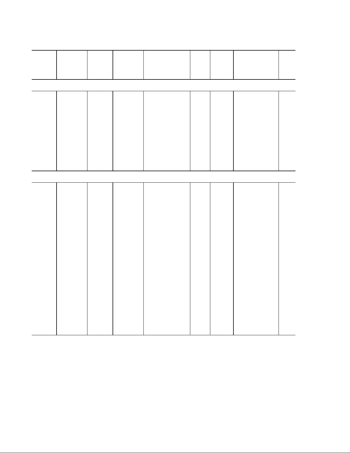
Table 2: AF-300E$ Drive Dimensions
Constant Constant Variable Variable
Torque Torque Torque Torque AF-300E$ Catalog List Price H x W x D Weight
Hp Rating Rated Output Hp Rating Rated Output Model No. No. GO-5E$ inches (lbs.)
150% 1 min.* Amps 115% 1 min.* Amps
230 VAC, 3 phase, 50/60 Hz Input, NEMA 1 Enclosure
0.5 3.0 N/A N/A 6KE$223F50X1A1 D5501 810. 10.24 x 4.33 x 4.53 5.3
1 5.0 N/A N/A 6KE$223001X1A1 D5502 860. 10.24 x 4.33 x 5.12 5.3
2 8.0 N/A N/A 6KE$223002X1A1 D5503 920. 10.24 x 5.91 x 5.71 8.4
3 11.0 N/A N/A 6KE$223003X1A1 D5504 990. 10.24 x 5.91 x 5.71 8.4
5 17.0 N/A N/A 6KE$223005X1A1 D5505 1,220. 10.24 x 5.91 x 5.71 8.4
7.5 25.0 10 29.0 6KE$223007X1A1 D5506 1,520. 10.24 x 8.66 x 7.68 13
10 33.0 15 42.0 6KE$223010X1A1 D5507 1,850. 10.24 x 8.66 x 7.68 13
15 46.0 20 55.0 6KE$223015X1A1 D5508 2,475. 15.75 x 9.84 x 7.68 25
20 59.0 25 68.0 6KE$223020X1A1 D5509 3,120. 15.75 x 9.84 x 7.68 25
25 74.0 30 80.0 6KE$223025X1A1 D5510 3,705. 15.75 x 9.84 x 7.68 27
30 87.0 N/A N/A 6KE$223030X1A1 D5511 4,300. 15.75 x 9.84 x 7.68 27
460 VAC, 3 phase, 50/60 Hz Input, NEMA 1 Enclosure
1 2.5 N/A N/A 6KE$243001X1A1 D5512 1,100. 10.24 x 5.91 x 5.71 8.4
2 3.7 N/A N/A 6KE$243002X1A1 D5513 1,180. 10.24 x 5.91 x 5.71 8.4
3 5.5 N/A N/A 6KE$243003X1A1 D5514 1,270. 10.24 x 5.91 x 5.71 8.4
5 9.0 N/A N/A 6KE$243005X1A1 D5515 1,560. 10.24 x 5.91 x 5.71 8.4
7.5 13.0 10 16.5 6KE$243007X1A1 D5516 1,950. 10.24 x 8.66 x 7.68 14
10 18.0 15 23.0 6KE$243010X1A1 D5517 2,375. 10.24 x 8.66 x 7.68 14
15 24.0 20 30.0 6KE$243015X1A1 D5518 3,175. 15.75 x 9.84 x 7.68 25
20 30.0 25 37.0 6KE$243020X1A1 D5519 4,000. 15.75 x 9.84 x 7.68 25
25 39.0 30 44.0 6KE$243025X1A1 D5520 4,750. 15.75 x 9.84 x 7.68 27
30 45.0 N/A N/A 6KE$243030X1A1 D5521 5,510. 15.75 x 9.84 x 7.68 27
30 45.0 40 52.0 6KE$243035X1A1 D5522 6,350. 33.5 x 13.4 x 9.65 89
40 60.0 50 66.0 6KE$243040X1A1 D5523 7,050. 33.5 x 13.4 x 9.65 89
50 75.0 60 77.0 6KE$243050X1A1 D5524 8,560. 33.5 x 14.8 x 9.65 100
60 91.0 75 96.0 6KE$243060X1A1 D5525 9,955. 39.4 x 14.8 x 9.65 111
75 112.0 100 124.0 6KE$243075X1A1 D5526 11,965. 39.4 x 14.8 x 9.65 122
100** 150.0 125 156.0 6KE$243100X1A1 D5527 14,915. 43.3 x 14.8 x 10.63 144
125** 176.0 150 180.0 6KE$243125X1A1 D5528 17,540. 47.3 x 20.9 x 12.4 221
150** 210.0 200 253.0 6KE$243150X1A1 D5529 19,830. 57.1 x 20.9 x 14.2 287
200** 304.0 250 304.0 6KE$243200X1A1 D5531 24,070. 57.1 x 20.9 x 14.2 298
250** 377.0 300 377.0 6KE$243250X1A1 D5532 28,135. 57.1 x 26.8 x 14.2 430
300** 415.0 350 415.0 6KE$243300X1A1 D5533 30,425. 57.1 x 26.8 x 14.2 430
* Verify the full load rated current of the motor to which the drive will be applied.
4-001
** A DC Link Inductor is shipped as a separate item (Ratings equal to and greater than 100 Hp)
and is to be connected to Drive Power Terminals P1 and P+. The DC Link Inductor is open core
design. If single unit construction is required refer to the Panel Section of the manual.
Note: In variable torque applications, Function Code 86 (Motor Hp Capability) needs to be changed to
Set Drive Hp vs. Load Hp. 40 Hp and above is 460-480 VAC input, variable torque applications only.
2-8
Page 14
Table 3: CE Labeled AF-300E$ and Fuji Electric G9 Products
Constant Variable
NEW
PRODUCTS
AF-300E$ 415 VAC Three Phase
NEMA 1 7.5 10 6KE$243007X1B1 D5629 1,975. 14
CE Labeled 10 15 6KE$243010X1B1 D5630 2,400. 14
UL/CSA 15 20 6KE$243025X1B1 D5631 3,200. 25
AF-300E$ 415 VAC Three Phase
NEMA 4 3 3 6KE$243003X4B1 D5637 1,490. 12
CE Labeled 5 5 6KE$243005X4B1 D5638 1,780. 12
UL/CSA 7.5 10 6KE$243007X4B1 D5639 2,240. 20.5
NEMA 12 20 25 6KE$243007X2B1 D5642 4,400. 25
CE Labeled 25 30 6KE$243007X2B1 D5643 5,150. 27
UL/CSA 30 6KE$243007X2B1 D5644 5,910. 277
Torque Torque Model No. Catalog List Price Weight
Hp Rating Hp Rating No. GO-5E$ (lbs.)
1 1 6KE$243001X1B1 D5625 1,135. 8.4
2 2 6KE$243002X1B1 D5626 1,205. 8.4
3 3 6KE$243003X1B1 D5627 1,295. 8.4
5 5 6KE$243005X1B1 D5628 1,585. 8.4
20 25 6KE$243020X1B1 D5632 4,025. 25
25 30 6KE$243025X1B1 D5633 4,775. 27
30 6KE$243030X1B1 D5634 5,535. 27
1 1 6KE$243001X4B1 D5635 1,320. 12
2 2 6KE$243002X4B1 D5636 1,400. 12
10 15 6KE$243007X2B1 D5640 2,665. 20.5
15 20 6KE$243007X2B1 D5641 3,575. 25
GE Fuji has expanded its product
offering again, with a new line of CE
labeled AF-300E$ drives. The drives
are available in 415 VAC (380 VAC to
460 VAC UL, CSA only) ratings.
Drives from 1 - 30 Hp also carry the
UL and CSA approvals in addition to
the CE Mark. Drives rated at 40 Hp
and above carry the CE label
exclusively. The units have the same
variable torque and constant torque
ratings as the existing line of AF300E$ drives. In addition to the new
CE labeled drives, GE Fuji offers a
complete compatible line of RFI
filters.
Fuji Electric G9 415 VAC Open Chassis (IP00)
40 FRN30G9S-4EN D5645 7,050. 79
50 FRN37G9S-4EN D5646 8,560. 82
60 FRN45G9S-4EN D5647 9,955. 97
75 FRN55G9S-4EN D5648 12,750. 112
CE Labeled 100 FRN75G9S-4EN D5649 15,245. 134
125 FRN90G9S-4EN D5650 18,580. 194
150 FRN110G9S-4EN D5651 21,890. 194
200 FRN160G9S-4EN D5652 26,425. 2775
250 FRN200G9S-4EN D5653 31,080. 390
300 FRN220G9S-4EN D5654 36,400. 390
Compatible RFI Filters
Model No. Cat. No. List Price Weight
EFL015G94 CE Filter 1 - 2 Hp A3281 295. 4.4
EFL040G94 CE Filter 3 - 5 Hp A3282 750. 4.4
EFL075G94 CE Filter 7.5 - 10 Hp A3283 1,215. 5.9
CE Compliant EFL150G94 CE Filter 15 - 20 Hp A3284 1,990. 12
EFL220G94 CE Filter 25 - 30 Hp A3285 2,735. 12
RS3120DF CE Filter 40 - 50 Hp A3286 3,440. 30
RS3180DF CE Filter 60 - 100 Hp A3287 4,465. 49
RS3280DF CE Filter 125 - 200 Hp A3288 5,815. 85
RS3380DF CE Filter 250 - 300 Hp A3289 7,720. 93
4-001C
2-9
Page 15
Table 4: AF-300E$ Drive Ratings Efficiency and Watts Loss
230 VAC
VAC
Constant Torque Variable Torque
Hp* Output Current Output Power Efficiency % Watts Loss Watts Loss
Catalog No. Const Var Const Var KVA KW 2K Hz 15K Hz 2K Hz 15K Hz 15K Hz Internal
Trq Trq Trq Trq DB
- Three Phase
6KE$223F50X1A1 0.5 0.5 3 3 1.2 0.4 90.0 87.5 40 50 44
6KE$223001X1A1 1 1 5 5 2 0.75 93.3 90.7 50 70 68
6KE$223002X1A1 2 2 8 8 3.1 1.5 94.7 92.7 80 110 75
6KE$223003X1A1 3 3 11 11 4.3 2.2 94.8 93.2 115 150 77
6KE$223005X1A1 5 5 17 17 6.7 3.7 95.4 93.8 170 230 93
6KE$223007X1A1 7.5 10* 25 29 9.9 5.5 96.0 94.4 220 310 415 138
6KE$223010X1A1 10 15* 33 42 13 7.5 96.0 94.5 300 415 685 188
6KE$223015X1A1 15 20* 46 55 18 11 95.4 93.8 510 685 720
6KE$223020X1A1 20 25* 59 68 23 15 96.5 95.2 530 720 890
6KE$223025X1A1 25 30* 74 80 29 18.5 96.3 95.2 690 890 1160
6KE$223030X1A1 30 87 34 22 96.5 94.7 780 1160
460
6KE$243001X1A1, B1 1 1 2.5 2.5 2 0.75 93.3 88.0 50 90 68
6KE$243002X1A1, B1 2 2 3.7 3.7 2.9 1.5 95.7 92.7 65 110 75
6KE$243003X1A1, B1 3 3 5.5 5.5 4.4 2.2 96.1 93.2 85 150 77
6KE$243005X1A1, B1 5 5 9 9 7.2 3.7 97.0 93.8 110 230 93
6KE$243007X1A1, B1 7.5 10* 13 16.5 10 5.5 97.5 94.5 140 300 400 138
6KE$243010X1A1, B1 10 15* 18 23 14 7.5 97.3 94.7 200 400 525 188
6KE$243015X1A1, B1 15 20* 24 30 19 11 97.1 95.2 315 525 610
6KE$243020X1A1, B1 20 25* 30 37 23 15 97.7 95.9 340 610 780
6KE$243025X1A1, B1 25 30* 39 44 31 18.5 97.6 95.8 450 780 970
6KE$243030X1A1, B1 30 45 45 35 22 97.7 95.6 510 970
6KE$243035X1A1 40* 45 52 35 22 97.1 96.2 650 850
6KE$243040X1A1 40 50* 60 66 47 30 97.2 96.3 850 1100 1050
6KE$243050X1A1 50 60* 75 77 59 37 97.6 96.8 900 1200 1150
6KE$243060X1A1 60 75* 91 96 72 45 97.8 97.1 1000 1300 1250
6KE$243075X1A1 75 100* 112 124 89 55 98.0 97.2 1150 1550 1500
6KE$243100X1A1 100 125* 150 156 119 75 98.0 97.9 1500 1600 1850
6KE$243125X1A1 125 150* 176 180 140 90 98.1 97.9 1750 2000 2000
6KE$243150X1A1 150 200* 210 253 202 132 98.2 97.9 2050 2350 2300
6KE$243200X1A1 200 250* 304 304 242 160 98.1 97.8 2850 3250 3150
6KE$243250X1A1 250 300* 377 377 300 200 98.1 97.9 3500 4000 3800
6KE$243300X1A1 300 350* 415 415 330 220 98.3 98.0 3850 4450 4300
* Verify the full load rated current of the motor to which the drive will be applied.
- Three Phase
2K Hz 10K Hz 2K Hz 10K Hz
2K Hz 6K Hz 2K Hz 6K Hz
4-002
Note: In variable torque applications, Function Code 86 (Motor Hp Capability) needs to be changed to Set Drive Hp vs. Load Hp.
2-10
Page 16
Section 3: Installation Guidelines
Installation Environment
Install the drive in an indoor location that meets the following
requirements:
— The ambient temperature is between -10°C and +50°C
— The relative humidity is between 20% and 90%. Avoid
— Do not install in any location subject to direct sunlight,
— The drive should be installed at an elevation below
Example:
°
F to +122°F). (Remove the ventilation cover when
(+14
the temperature exceeds +40
any location subject to condensation, freezing, or where
the drive would come in contact with water.
dust, corrosive gas, inflammable gas, or oil mist.
1000 meters (3281 feet). Installation above 1000
meters (3300 feet) will need to be derated 1% per 333
feet.
5 Hp, 460 VAC, output current 9 amps. Application
altitude 3900 feet.
% derate = x 1% = 1.8%
3900 - 3300
( )
333
°
C [+104°F].)
CAUTION:
The mounting wall for the drive must be constructed of
heat resistant material because during operation, the
temperature of the Inverter's cooling fins rises to approxi-
mately 90 degrees C (194° F).
NOTE: When installing two or more drives in close
proximity, allow sufficient space as shown in Figure 3-1 and
install them in a horizontal row. If they must be installed in
a vertical column, at least 19.7 inches (50cm) internal
space must be provided between each one or a ventilation
baffle should be provided to prevent the ambient temperature from rising.
— Mounting screws or bolts should be of appropriate size
— See the appropriate view in Figure 3-2 for the location
— After removing the knockouts in the wiring lead in
for weight of drive.
of mounting holes.
plate, install the rubber bushings supplied to prevent
cable damage and to minimize dust entry.
4.8” (12CM) or more
(9 amps) x = 8.84 amps derated
Motor derate may also be required, contact motor
manufacturer.
— Vibration should be less than 0.6G.
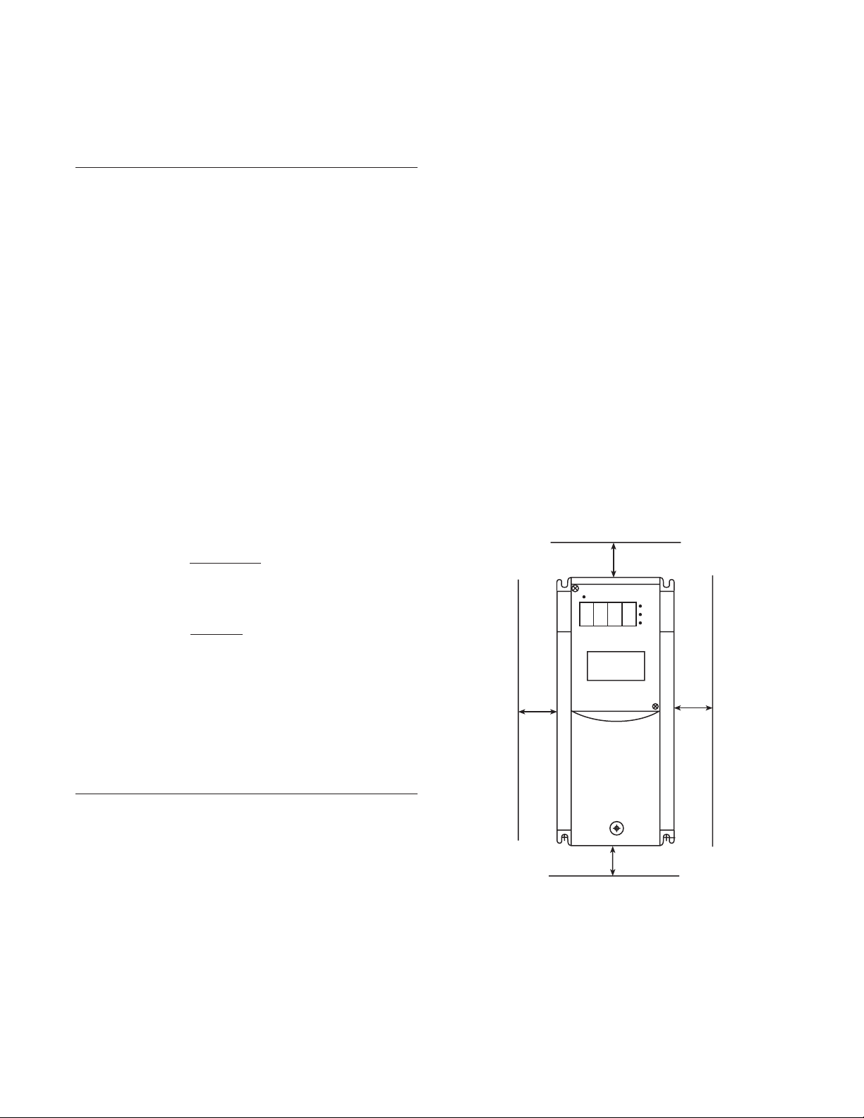
Installation Mounting Clearance
CAUTION:
Because the ambient temperature greatly
affects drive life and reliability, do not install the drive in any
location that exceeds the allowable temperatures.
— Install at a sufficient distance from other equipment,
walls, or wiring ducts as shown in Figure 3-1 (these
clearances are required to allow the heat generated by
the drive to escape).
— Install the drive perpendicular to the ground and with
the lettering right side up. (If the drive is installed
upside-down or horizontally, heat build-up will occur.)
100 - 1.8
( )
100
output current.
2.0” (5 CM)
or more
4.8” (12CM) or more
Figure 3-1. DRIVE MOUNTING CLEARANCE
2.0” (5 CM)
or more
3-1
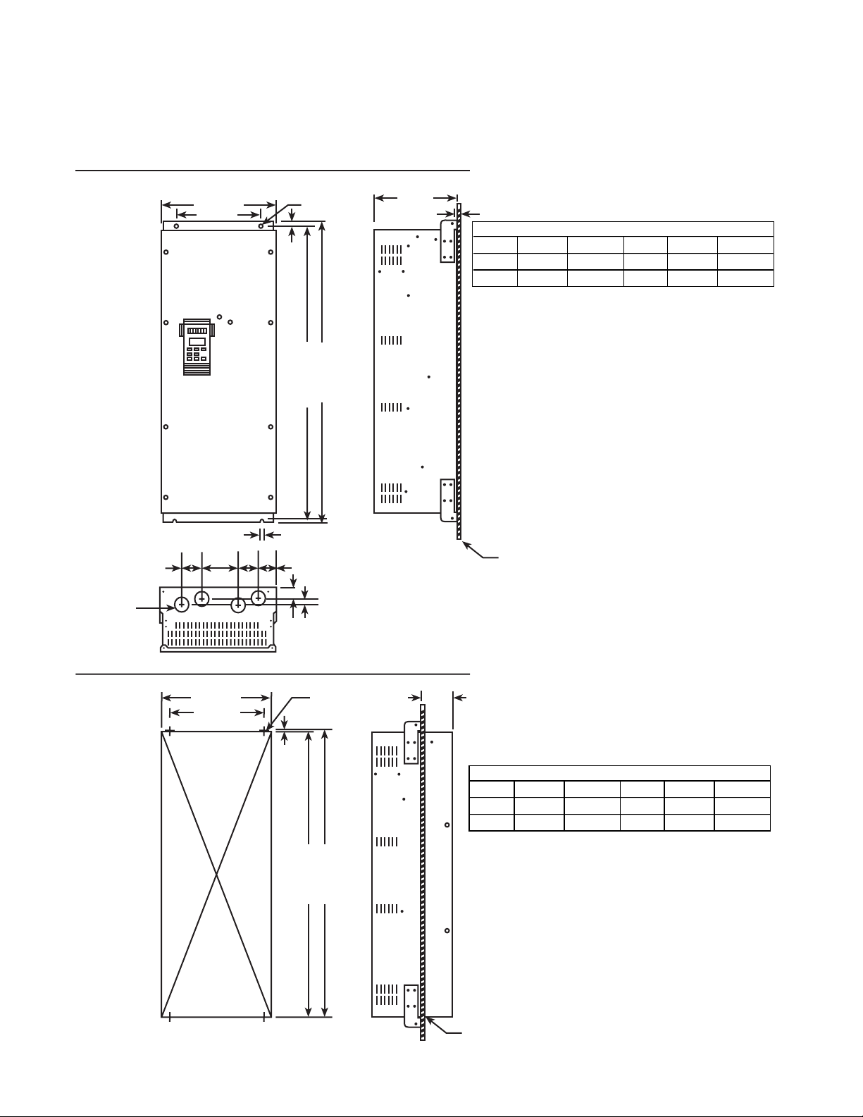
Page 17
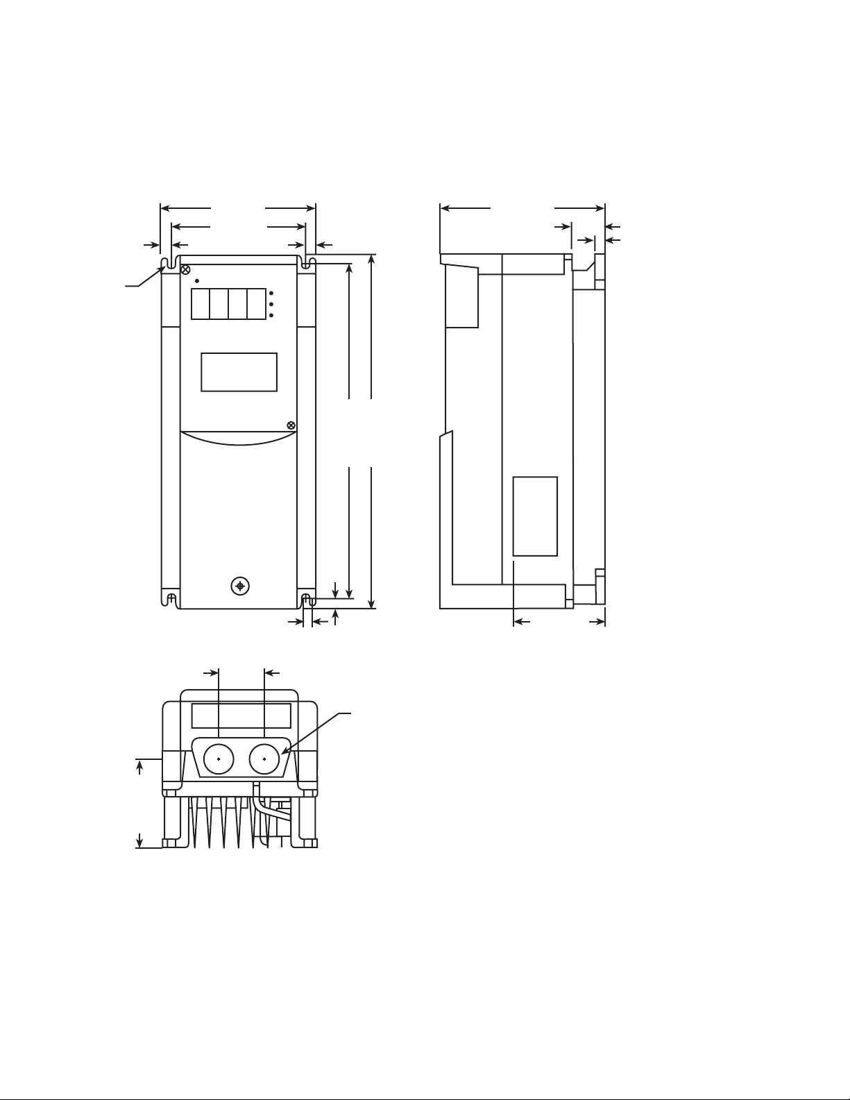
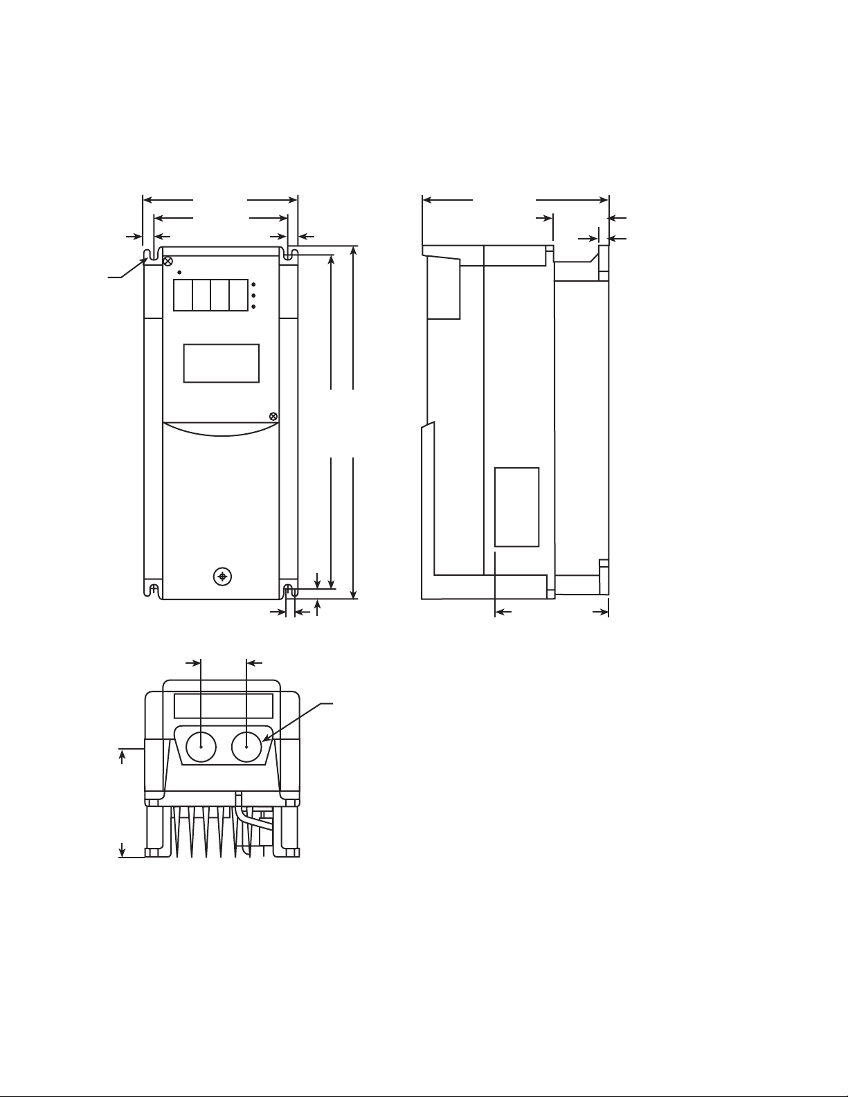
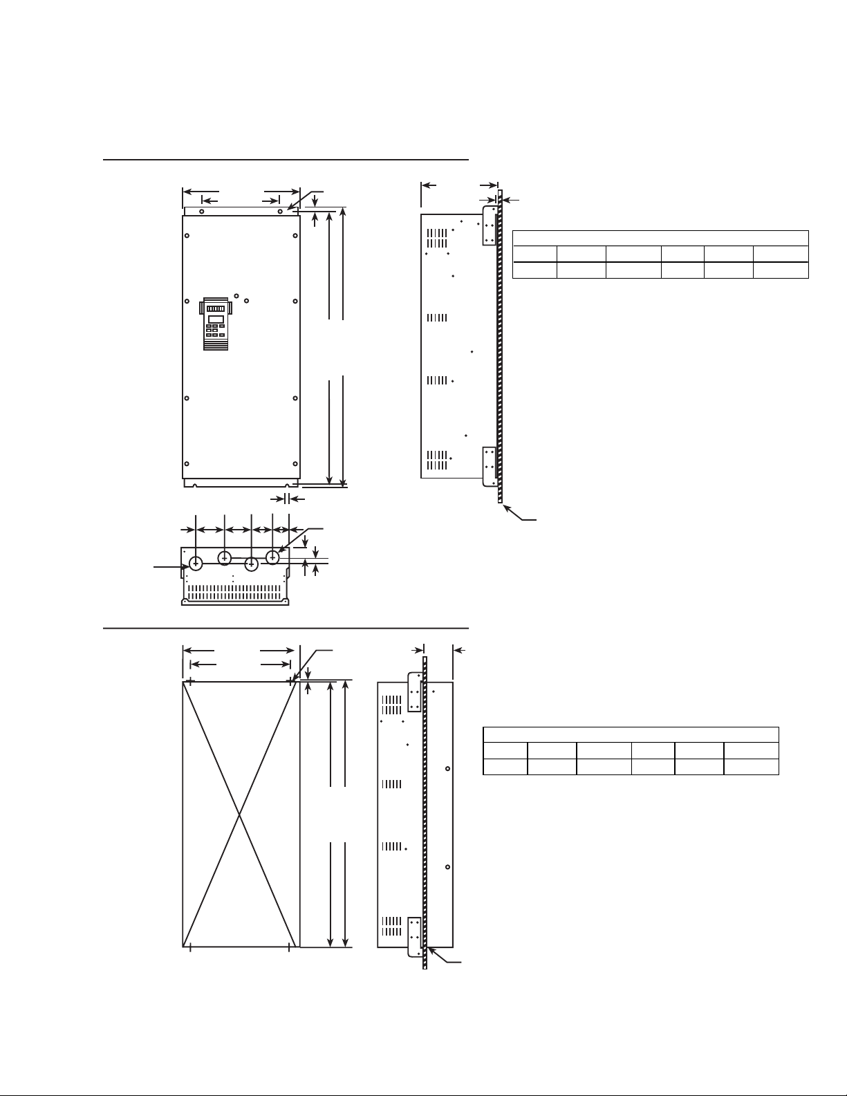
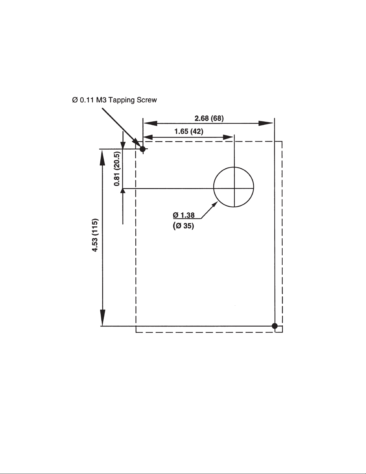
Dimensions 0.5 Hp 230 VAC
Dimensions in inches (mm)
0.24 (6)
4.33 (110)
3.78 (96)
0.28 (7) 0.28 (7)
9.69 (246)
.28 (7)
10.24 (260)
4.53 (115)
0.87 (22)
0.24 (6)
2.52 (64)
0.24 (6)
2.52 (64)
1.26 (32)
0.87 (22)
BUSHING SUPPLIED
3-2
Page 18
Dimensions 1 Hp 230 VAC
Dimensions in inches (mm)
0.24 (6)
4.33 (110)
3.78 (96)
0.28 (7) 0.28 (7)
9.69 (246)
.28 (7)
512 (130)
1.46 (37)
0.24 (6)
10.24 (260)
3.11 (79)
0.24 (6)
3.11 (79)
1.26 (32)
0.87 (22)
BUSHING SUPPLIED
3-3
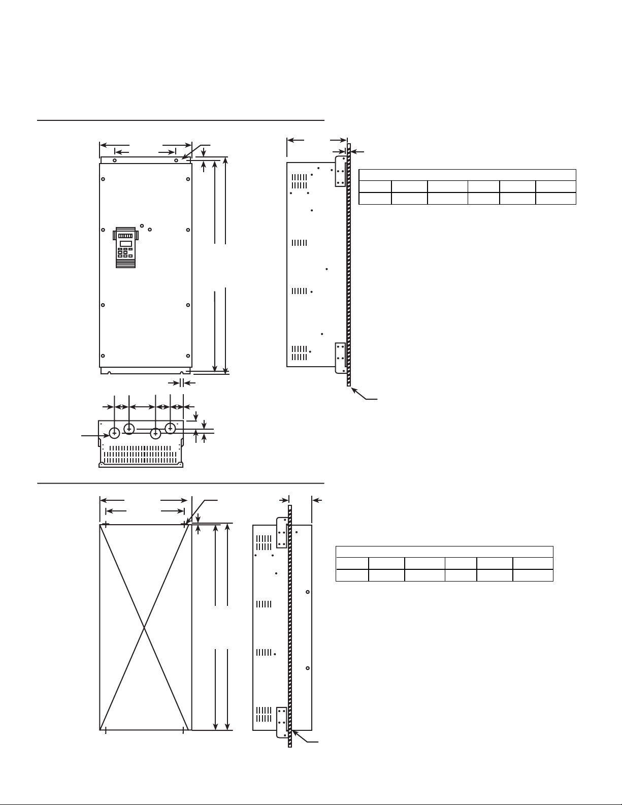
Page 19
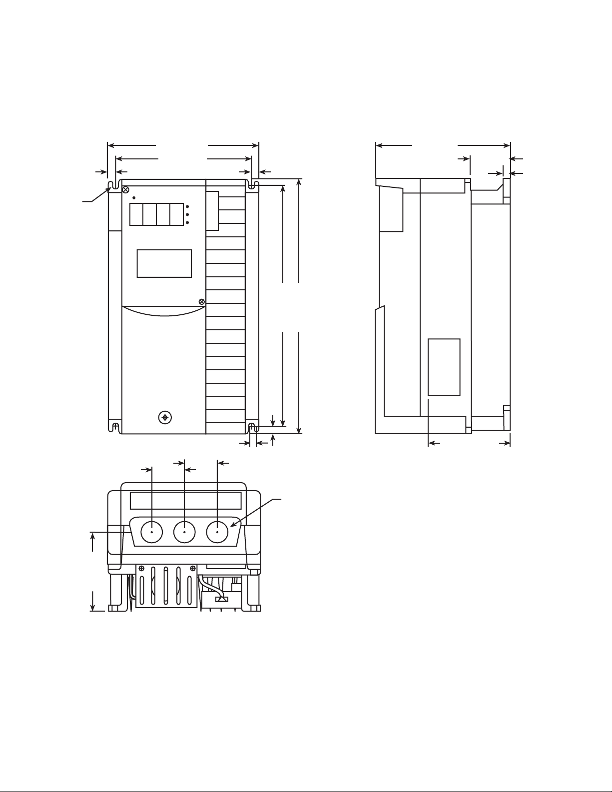
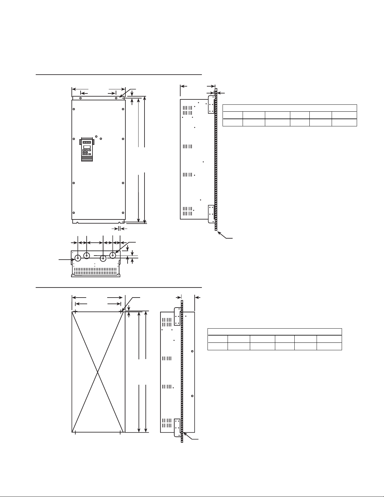
Dimensions 2, 3, 5 Hp 230 VAC and 1, 2, 3, 5 Hp 460 VAC
Dimensions in inches (mm)
0.24 (6)
5.91 (150)
5.35 (136)
0.28 (7) 0.28 (7)
9.69 (246)
.28 (7)
5.71 (145)
2.05 (52)
0.24 (6)
10.24 (260)
3.7 (94)
1.26 (32)
0.24 (6)
3.7 (94)
1.26 (32)
0.87 (22)
BUSHING SUPPLIED
3-4
Page 20
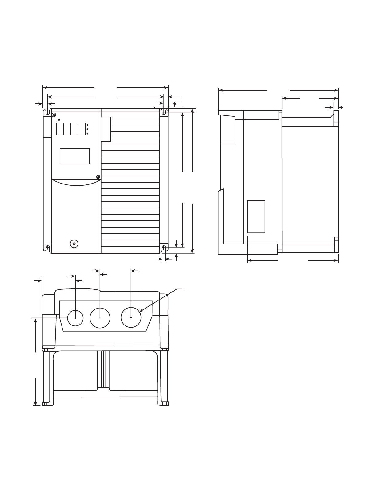
Dimensions 7.5 , 10 Hp 230 and 460 VAC
Dimensions in inches (mm)
0.47 (12)
2.26 (57.5)
1.81 (46)
8.66 (220)
7.72 (196)
2.07 (52.5)
0.39 (10)
0.47 (12)
0.47 (12)
9.37 (238)
0.39 (10)
0.87 (22)
7.68 (195)
3.82 (97)
0.39 (10)
10.24 (260)
6.18 (157)
6.18 (157)
BUSHING SUPPLIED
3-5
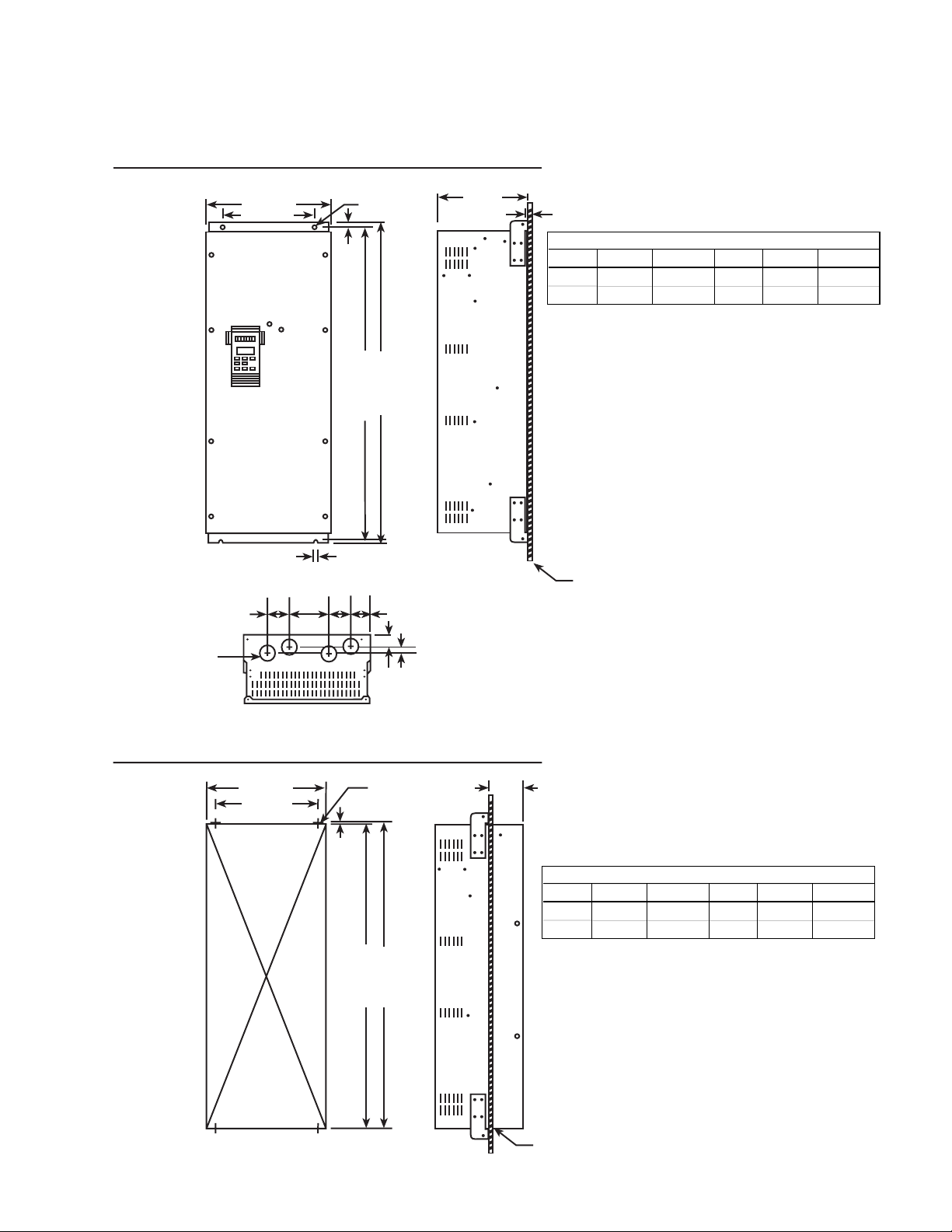
Page 21
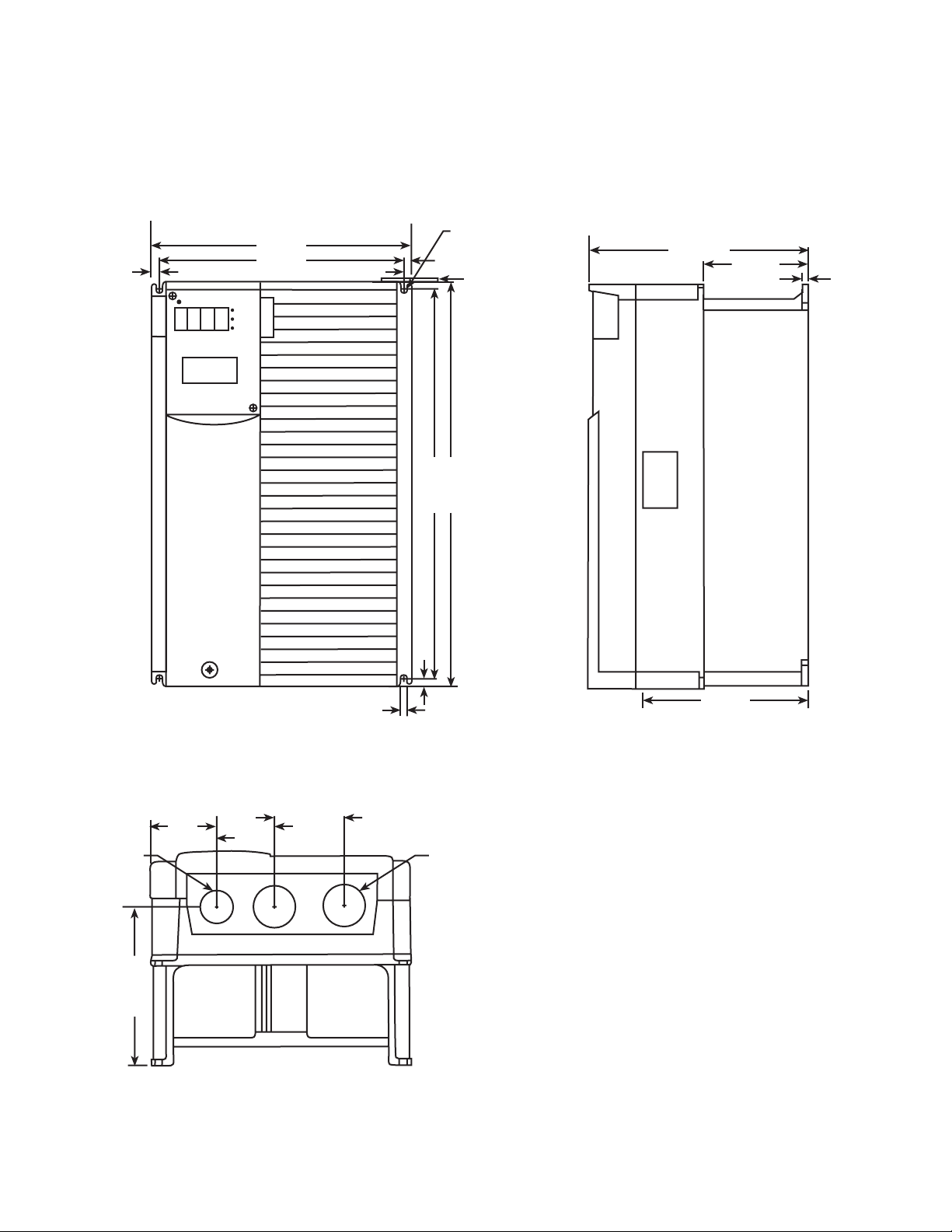
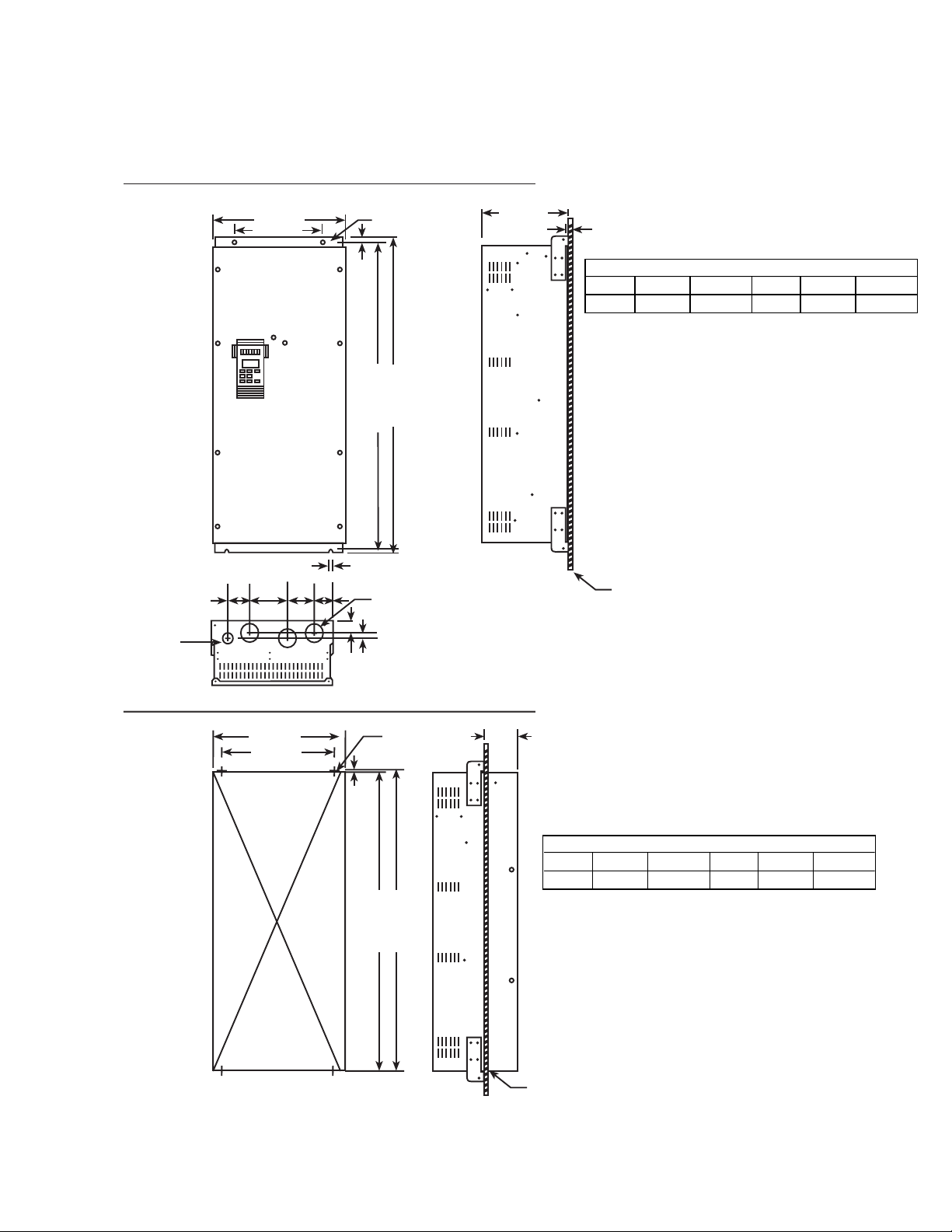
Dimensions 15, 20, 25, 30 Hp 230 and 460 VAC
Dimensions in inches (mm)
0.47 (12)
9.84 (250)
8.90 (226)
2-0.39 (10)
0.47 (12)
14.88 (378)
0.39 (10)
0.47 (12)
15.75 (400)
7.68 (195)
3.78 (96)
0.39 (10)
1.34 (34)
2.48 (63)
5.93 (150.5)
2.17 (55)
2.42 (61.5)
.0.39 (10)
6.02 (153)
BUSHING SUPPLIED
1.65 (42)
3-6
Page 22
Dimensions 35 , 40 Hp 460 VAC
Dimensions in inches (mm)
BACK PANEL MOUNTING
4-ø 1.9 (48)
wire inlet
Knock out hole
13.4 (340)
9.5 (240)
2.6
(65)
3.8
(97)
AF-300E$
2.8
(70)
2.3
(58)
0.5 (12)
0.4 (10)
2-ø 0.4 (10)
32.7 (830)
33.5 (850)
9.7 (245)
0.1 (2.3)
AF-300E$ Back-Panel Mounting: Interior Watts Loss
Hp (CT) 0 setting 10 setting Hp (VT) 0 setting 10 setting
35 40 650 850
40 850 1100 50 900 1050
BACK PANEL
THROUGH PANEL MOUNTING
12.8 (326)
9.5 (240)
1.6 (41)
1.0 (25)
4-MB (0.3) 4.1 (105)
0.4 (9)
32.7 (830)
32.0 (812)
AF-300E$ Thru-Panel Mounting: Interior Watts Loss
Hp (CT) 0 setting 10 setting Hp (VT) 0 setting 10 setting
35 40 195 255
40 255 330 50 270 315
BACK PANEL
3-7
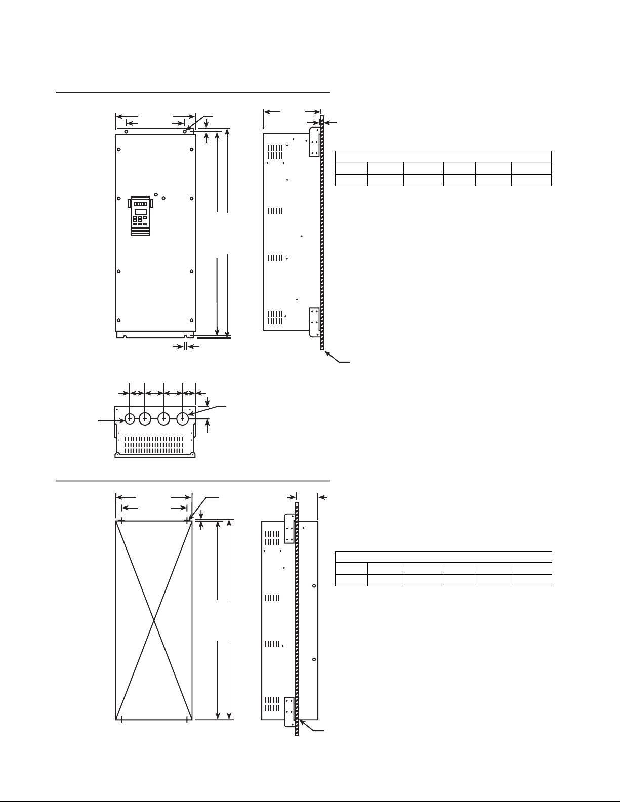
Page 23
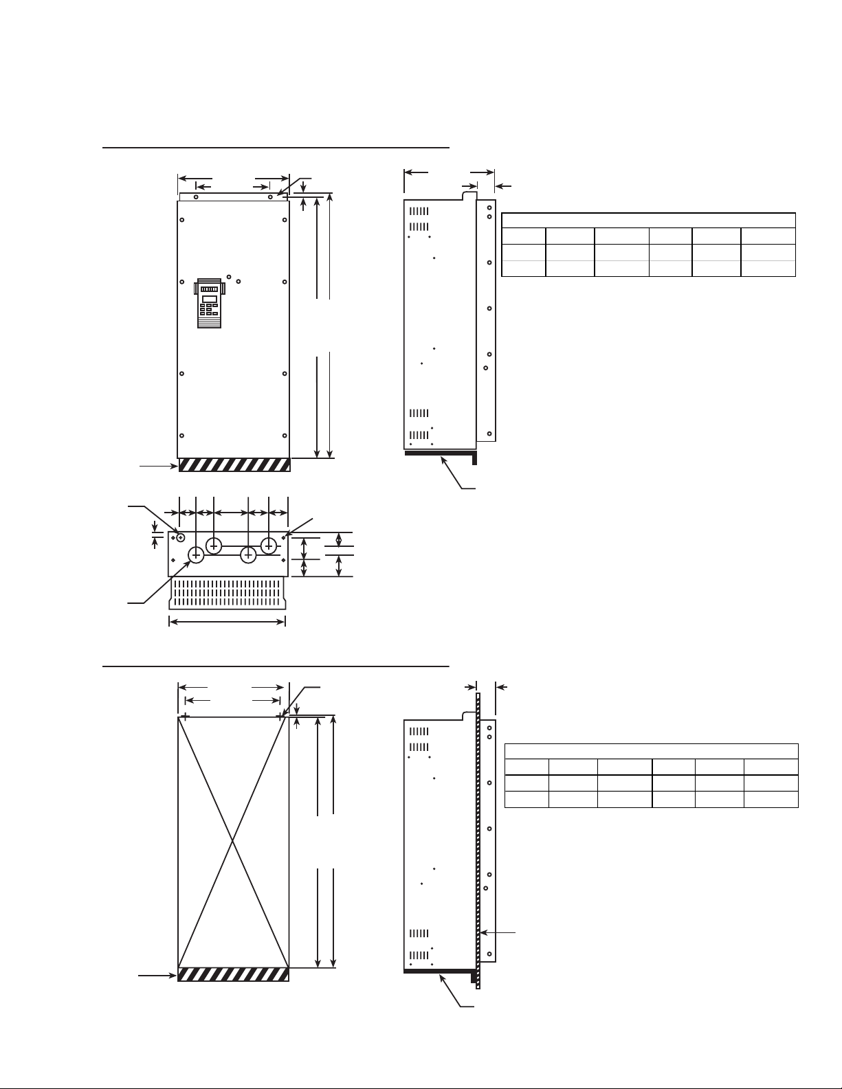
Dimensions 50 Hp 460 VAC
Dimensions in inches (mm)
BACK PANEL MOUNTING
4-ø 1.9 (48)
wire inlet
Knock out hole
2.6
(65)
14.8 (375)
10.8 (275)
AF-300E$
3.8
(97)
2.8
(70)
2.3
(58)
0.5 (12)
0.4 (10)
2-ø 0.4 (10)
32.7 (830)
33.5 (850)
9.7 (245)
0.1 (2.3)
AF-300E$ Back-Panel Mounting: Interior Watts Loss
Hp (CT) 0 setting 10 setting Hp (VT) 0 setting 10 setting
50 900 1200 60 950 1150
BACK PANEL
THROUGH PANEL MOUNTING
14.2 (361)
10.8 (275)
1.6 (41)
1.0 (25)
4-MB (0.3) 4.1 (105)
0.4 (9)
32.7 (830)
32.0 (812)
AF-300E$ Thru-Panel Mounting: Interior Watts Loss
Hp (CT) 0 setting 10 setting Hp (VT) 0 setting 10 setting
50 270 360 60 285 345
BACK PANEL
3-8
Page 24
Dimensions 60, 75 Hp 460 VAC
Dimensions in inches (mm)
BACK PANEL MOUNTING
4-ø 1.9 (48)
wire inlet
Knock out hole
14.8 (375)
10.8 (275)
2.6
(65)
AF-300E$
(100)
3.8
0.4 (10)
2.8
(70)
2-ø 0.4 (10)
0.5 (12)
38.61 (980)
3.7
(93)
9.7 (245)
0.1 (2.3)
AF-300E$ Back-Panel Mounting: Interior Watts Loss
Hp (CT) 0 setting 10 setting Hp (VT) 0 setting 10 setting
60 1000 1300 75 1050 1250
75 1150 1550 100 1300 1500
39.4 (1000)
BACK PANEL
THROUGH PANEL MOUNTING
14.2 (361)
10.8 (275)
0.4 (9)
1.6 (41)
4-M8 (0.3)
38.6 (980)
37.9 (962)
0.4 (10)
4.1 (105)
AF-300E$ Thru-Panel Mounting: Interior Watts Loss
Hp (CT) 0 setting 10 setting Hp (VT) 0 setting 10 setting
60 300 390 75 315 375
75 345 415 100 390 450
BACK PANEL
3-9
Page 25
Dimensions 100 Hp 460 VAC
Dimensions in inches (mm)
BACK PANEL MOUNTING
4 ø 1.9 (48)
wire inlet
Knock out hole
14.8 (375)
10.8 (275)
3.2
(80)
3.6
(92)
AF-300E$
3.6
(92)
2.5
(62)
0.5 (12)
0.4 (10)
2-ø 0.4 (10)
42.5 (1080)
43.3 (1100)
3-ø 2.5 (64)
wire inlet
Knock out hole
106 (270)
0.1 (2.3)
AF-300E$ Back-Panel Mounting: Interior Watts Loss
Hp (CT) 0 setting 10 setting Hp (VT) 0 setting 10 setting
100 1500 1600 125 1700 1850
BACK PANEL
THROUGH PANEL MOUNTING
14.2 (361)
10.8 (275)
1.7 (43)
0.4 (9)
4-M8 (0.3)
42.5 (1080)
41.8 (1062)
4.1 (105)
AF-300E$ Thru-Panel Mounting: Interior Watts Loss
Hp (CT) 0 setting 10 setting Hp (VT) 0 setting 10 setting
100 450 480 125 510 555
NOTE: Drive includes a separately mounted DC Link Reactor.
BACK PANEL
NOTE: Drive includes a separately mounted DC Link Reactor. See Page 4-10 for details
3-10
Page 26
Dimensions 125 Hp 460 VAC
Dimensions in inches (mm)
BACK PANEL MOUNTING
4 ø 1.9 (48)
wire inlet
Knock out hole
5.9
(150)
20.9 (530)
16.9 (430)
5.5
(139)
AF-300E$
3.7
(94)
2.4
(62)
2-ø 0.6 (15)
0.7 (18)
0.4 (10)
3-ø 2.5 (64)s
45 (1170)
47.2 (1200)
12.4 (315)
0.1 (3.2)
AF-300E$ Back-Panel Mounting: Interior Watts Loss
Hp (CT) 0 setting 10 setting Hp (VT) 0 setting 10 setting
125 1750 2000 150 1800 2000
BACK PANEL
THROUGH PANEL MOUNTING
20 (510)
16.9 (430))
1.9 (48)
1.0 (25)
0.5 (12.5)
45.1 (1145)
4-M12 0.5
46.1 (1170)
4.9 (125)
AF-300E$ Thru-Panel Mounting: Interior Watts Loss
Hp (CT) 0 setting 10 setting Hp (VT) 0 setting 10 setting
125 525 600 150 540 600
NOTE: Drive includes a separately mounted DC Link Reactor
BACK PANEL
NOTE: Drive includes a separately mounted DC Link Reactor. See Page 4-10 for details
3-11
Page 27
Dimensions 150 Hp 460 VAC
Dimensions in inches (mm)
BACK PANEL MOUNTING
ø 1.9 (48)
wire inlet
Knock out hole
3.2
(80)
20.9 (530)
16.9 (430)
AF-300E$
5.4
(136)
3.6
(92)
2.7
(68)
2-ø 0.6 (15)
0.7 (18)
0.6 (15)
3-ø 2.5 (64)s
55.9 (1420)
57.1 (1450)
14.2 (360)
0.1 (3.2)
AF-300E$ Back-Panel Mounting: Interior Watts Loss
Hp (CT) 0 setting 10 setting Hp (VT) 0 setting 10 setting
150 2050 2350 200 2050 2300
BACK PANEL
THROUGH PANEL MOUNTING
20 (510)
16.9 (430)
3.2 (81)
0.8 (20)
0.5 (12.5)
54.9 (1395)
4-M12 0.5
55.9 (1420)
5.5 (140)
AF-300E$ Thru-Panel Mounting: Interior Watts Loss
Hp (CT) 0 setting 10 setting Hp (VT) 0 setting 10 setting
150 615 705 200 615 690
NOTE: Drive includes a separately mounted DC Link Reactor.
BACK PANEL
NOTE: Drive includes a separately mounted DC Link Reactor. See Page 4-10 for details
3-12
Page 28
Dimensions 200 Hp 460 VAC
Dimensions in inches (mm)
BACK PANEL MOUNTING
4 ø 1.9 (48)
wire inlet
Knock out hole
3.7
(95)
20.9 (530)
16.9 (430)
AF-300E$
6.4
(162)
5.4
(138)
3.4
(86)
2-ø 0.6 (15)
0.7 (18)
0.6 (15)
3-ø 2.5 (90)
55.9 (1420)
57.1 (1450)
14.2 (360)
0.1 (3.2)
AF-300E$ Back-Panel Mounting: Interior Watts Loss
Hp (CT) 0 setting 10 setting Hp (VT) 0 setting 10 setting
200 2850 3250 250 2800 3150
BACK PANEL
THROUGH PANEL MOUNTING
20 (510)
16.9 (430)
2.8 (71)
0.6 (15)
0.5 (12.5)
54.9 (1395)
4-M12 0.5
55.9 (1420)
5.5 (140)
AF-300E$ Thru-Panel Mounting: Interior Watts Loss
Hp (CT) 0 setting 10 setting Hp (VT) 0 setting 10 setting
200 855 975 250 840 945
NOTE: Drive includes a separately mounted DC Link Reactor
BACK PANEL
NOTE: Drive includes a separately mounted DC Link Reactor. See Page 4-10 for details
3-13
Page 29
Dimensions 250, 300 Hp 460 VAC
Dimensions in inches (mm)
BACK PANEL MOUNTING
BRACKET AREA
(BRACKET
SUPPLIED BY
OTHERS, MUST
BE CAPABLE OF
SUPPORTING
500 LBS. MIN.)
4 ø 1.9 (48)
wire inlet
Knock out hole
4-ø 3.5 (90)
wire inlet
Knock out hole
1.6 (41)
2.4
(60)
4.3
(110)
26.8 (680)
22.8 (580)
6.7
(170)
24 (610)
AF-300E$
4.9
(125)
5.3
(134)
2-ø 0.6 (15)
0.7 (18)
43.
3.9
56.3 (1430)
57.1 (1450)
4-ø 0.6 (15)
3
(110)
1.6
(100)
14.2 (360)
4.5 (115)
AF-300E$ Back-Panel Mounting: Interior Watts Loss
Hp (CT) 0 setting 10 setting Hp (VT) 0 setting 10 setting
250 3500 4000 300 3450 3800
300 3850 4450 350 3900 4300
BRACKET REQUIRED FOR MOUNTING
(75)
(40)
THROUGH PANEL MOUNTING
26 (660)
22.8 (580)
2-M12 0.56
0.4 (10)
4.5 (115)
AF-300E$ Thru-Panel Mounting: Interior Watts Loss
Hp (CT) 0 setting 10 setting Hp (VT) 0 setting 10 setting
250 1050 1200 300 1035 1140
300 1155 1335 350 1170 1290
56.3 (1430)
55.7 (1415)
BRACKET AREA
(BRACKET
SUPPLIED BY
OTHERS, MUST
BE CAPABLE OF
SUPPORTING
500 LBS. MIN.)
NOTE: Drive includes a separately mounted DC Link Reactor
BRACKET REQUIRED FOR MOUNTING
BACK PANEL
NOTE: Drive includes a separately mounted DC Link Reactor. See Page 4-10 for details
3-14
Page 30
Keypad Mounting Hole (Panel Cutting)
Dimensions in inches (mm)
3-15
Page 31

Notes:
3-16
Page 32

Section 4: Wiring Procedures
WIRING PROCEDURES
REMOVE TERMINAL BLOCK COVER
Remove the terminal block cover as follows
(see Figure 4-1):
1. Remove the screw(s) located at the bottom of the
cover.
2. Press upward on bottom of cover and lift off.
3. See Figure 4-2 for the location of the Main Circuit
Terminal Block and the Control Circuit Terminal Block.
WARNING:
Some printed circuit boards and drive components may
contain hazardous voltage levels. If LED light CRG 1 on the
Base Driver Board is illuminated, hazardous voltages are
present in the drive circuit boards. Remove and lock out
power before you disconnect or reconnect wires, and
before you remove or replace fuses and circuit boards. Do
not attempt to service the drive until the LED indicator has
extinguished and the bus voltage has discharged to zero
CONTROL CIRCUIT WIRING
drive is wired at shipment for operation and frequency
setting through the keypad panel (frequency is set at 60 Hz.)
– See Figure 4-3 & 4-4 for wiring connections.
– See TABLE 4 for description of all terminals.
Make wire connections as shown in Figure 4-4 through 4-6
for desired mode of external operation through control
circuit terminals.
– See TABLE 4 for description of all terminals.
CAUTION:
The control circuit terminal wiring should be kept as far away
as possible from the main power wiring to prevent operational error due to noise interference. Never install both
types of wiring in the same duct or conduit. (A separation
distance of 4 inches [10 centimeters] or more is recommended.) If the control circuit wiring must cross the main
power wiring, it should cross at a right angle.
CAUTION:
volts.
Use shielded or twisted wire for the control circuit wiring
(wiring should be as short as possible, i.e. 65 feet or less [20
meters].) Connect outer covering of the shielded wires to the
drive ground terminal and leave the other end open, but
taped.
Figure 4-1. REMOVING THE FRONT COVER
CAUTION:
Install a supressor in parallel with any relays or solemoid
type coils that may be close to the drive to prevent noise
from causing drive misoperation.
DC RELAY
Figure 4-2.
AC CONTACTOR
4-1
Page 33

MAIN CIRCUIT WIRING
CAUTION:
Be sure that the power supply is never connected to the U,
3. Connect the 3-phase motor wires to the U, V, and W
V, W terminals or the N, P, DB terminals.
1. Connect the ground terminal as shown in the appropriate view of Figure 4-3 or 4-4. (Do not operate without
the unit being grounded.)
The ground wire must be as large and short as
possible (see TABLE 5 for application wiring list.)
2. Connect the power supply wires to the L1, L2, and L3
terminals of the Main Circuit Terminal Block as shown
NOTE: Motor will rotate counterclockwise when viewed
from the load side when connected normally. If the motor
rotates in reverse direction, interchange any two of the U,
V, or W terminal connections.
in the appropriate view of Figure 4-3 or 4-4. (See
TABLE 5 for description of all terminals and TABLE 4
for recommended wire sizes.)
Control Circuit Terminal
Block
terminals of the Main Circuit Terminal Block as shown
in the appropriate view of Figure 4-3 or 4-4. (See
TABLE 5 for description of all terminals and TABLE 4
for recommended wire sizes.)
Main Circuit Terminal
Block
Figure 4-3. TERMINAL BLOCKS
4-2
Page 34

Table 4: AF-300E$ Drive Cable Size Recommendations & Circuit Protection Rating
G
1
G
1
s
230V
DB UNIT & INCOMING POWER
HP CURRENT POWER DC LINK REACTOR
CONST VAR CONST VAR CABLE AMP CABLE AMP CIRCUIT
TRQ TRQ TRQ TRQ AWG QTY TERMINAL #
AW
QTY TERMINAL # FUSES BREAKER
0.5 0.5 3 3 16 1 – 14 1 – 6 15
1155161 – 141 – 10 15
2288141 – 141 – 15 15
3 3 11 11 14 1 – 14 1 – 20 20
5 5 17 17 10 1 – 10 1 – 30 30
7.5 10* 25 29 8 1 – 8 1 – 60 50
10 15* 33 42 6 1 – 6 1 – 80 60
15 20* 46 55 4 1 – 4 1 – 100 75
20 25* 59 68 2 1 – 2 1 – 125 100
25 30* 74 80 1 1 – 2 1 – 150 125
30 87 1 1 – 1/0 1 – 150 150
460V
DB UNIT & INCOMING POWER
HP CURRENT POWER DC LINK REACTOR
CONST VAR CONST VAR CABLE AMP CABLE AMP CIRCUIT
TRQ TRQ TRQ TRQ AWG QTY TERMINAL #
1 1 2.5 2.5 16 1 – 14 1 – 6 5
2 2 3.7 3.7 16 1 – 14 1 – 10 10
3 3 5.5 5.5 16 1 – 14 1 – 15 15
5599141 – 141 – 15 15
7.5 10 * 13 16.5 10 1 – 14 1 – 30 30
10 15 * 18 23 10 1 – 14 1 – 40 30
15 20 * 24 30 8 1 – 14 1 – 50 40
20 25 * 30 37 6 1 – 14 1 – 60 50
25 30 * 39 44 6 1 – 14 1 – 80 60
30 45 45 4 1 – 12 1 – 80 75
40 * 45 52 4 1 31812 12 1 321600 80 100
40 50 * 60 66 2 1 321600 12 1 321868 100 100
50 60 * 75 77 1/0 1 321868 10 1 31812 125 125
60 75 * 91 96 1/0 1 321868 8 1 321600 150 150
75 100 * 112 124 1/0 1 321868 6 1 321600 175 150
100 125 * 150 156 3/0 1 36927 6 1 321878 175 200
125 150 * 176 180 1/0 2 321868 6 1 321868 200 200
150 200 * 210 253 1/0 2 321868 4 1 36923 300 225
200 250 * 304 304 3/0 2 36929 4 2 171500-2 350 400
250 300 * 377 377 250 2 171500-2 4 2 171502-2 400 400
300 350 * 415 415 300 2 171500-2 4 2 171502-2 500 500
* In variable torque applications, Function Code 86 (Motor Hp Capacity) needs to be changed to Set Drive Hp vs. Load Hp.
40 Hp and above is 460-480 VAC input, VT applications only.
1 Device ratings such as system coordination, short-circuit rating and type must be carefully reviewed by the user.
2 Based on GE Fuji DB resistor designs. Other ratings require careful review.
3 Device ratings such as system coordination, short-circuit rating and type must be carefully reviewed by the user.
Note: Wire size from NEC table 310-16. Copper wire rated 60 Deg. C for 100 amps or less, 75 Deg. C for over 100 amps in 30 Deg. C
ambient and 1.25 times Drive rated amps. These are minimum wire sizes; consult and conform to local and national codes.
CAUTION: The grounding connector shall be sized in accordance with the NEC or Canadian Electrical Code. The connection shall be made
by a UL listed or CSA certified closed-loop terminal connector sized for the wire gauge involved. The connector is to be fixed using the
crimp tool specified by the connector manufacturer.
Recommend GE Spectra RMS MAG-BREAK Circuit Breakers.
CAUTION: Quick-acting bussman JKS or equivalent J-class AC line fuses are required on 30 Hp or lower Drives. Check local electrical code
for 40 Hp and higher.
AW
QTY TERMINAL # FUSES BREAKER
AC-LINE DEVICE
AC-LINE DEVICE
2
2
4-3
Page 35

Control Terminal Board 1⁄2 - 30 Hp
CAUTION
Remove Jumper from between terminals THR and
CM when thermal interlocks are used.
NOTE
Wiring connections for operation with kaypad
reference control.
CM-FWD and CM-THR terminals are jumpered
together at the factory.
Power Terminal Board
FUSES:
Reference UL power circuit
protection requirements.
Refer to Table 4 on page 4-4.
UL Listed non-time delay fuses
should be used.
✱
* Refer to Dynamic Braking Table on Page 4-16.
NOTE: P1 - P+ terminals are jumpered together at the factory.
Figure 4-4. 1⁄2 - 30 Hp TERMINAL BOARDS
4-4
Page 36

Control Terminal Board 40 - 300 Hp
CAUTION
Remove Jumper from between terminals THR and CM
when thermal interlocks are used.
CAUTION
Remove jumper from between terminals FWD and CM.
NOTE
Wiring connections for operation with kaypad reference
control.
CM-FWD and CM-THR terminals are jumpered
together at the factory.
Power Terminal Boards
40-75 Hp
100 – 300 Hp
NOTE: A DC Link Reactor is also shipped for connection between terminals P1 - P+, 100 Hp and greater.
Figure 4-5. 40 - 300 Hp TERMINAL BOARDS
4-5
Page 37

1⁄2 to 30 Hp AF-300E$ Drive Rating
Circuit
Breaker
380/460 VAC
3PH AC
50/60 Hz
L1
L2
L3
Main
Input
Power
U
V
W
Motor
Ground
+
CURRENT
_
Pulse Counter
Speed Pot
1-5K Ohm
REF
4 TO
20 mA
Frequency Meter 10V
(Movable coil type 10V)
_
_
0000
Start
Stop
2W
3
1
+
+
FWD
OFF
REV
FWD
OFF
REV
C1
13
2
+
12
11*
E(G)
P1
P+
DB
N-
Braking Section **
1/2 to 10 HP
P+
DB
12
Braking Resistor
FMA
FMP
FWD
REV
HLD
CM*
X1
X2
X3
X4
FAULT
30A
30B
30C
Y1
Y2
Y3
R-C
Breaking Section
15 to 30 HP
P+
P+
N- DB
N-
Thermal Switch
Power
On
Power
Off
P
P
DB
Customer
supplied
power for
}
contactor
coil
X5
BX
RST
CM*
THR
Y4
Y5
E(G)
CME*
Ground
12
Breaking
Unit
Any additional normally
closed protective interlocks
should be added in series.
12
Breaking
Resistor
*Terminal 11 should not be connected to either CM and/or CME.
** Refer to the Dynamic Braking Table on Page 4-13.
Figure 4-6. 1⁄2 - 30 Hp BASIC CONNECTION DIAGRAM
4-6
Page 38

40 to 300 Hp AF-300E$ Drive Rating
Curcuit
Breaker
380/460 VAC
460V
3PH AC
50/60 Hz
CURRENT
+
REF
4 TO
_
20 mA
Pulse Counter
VS
Speed Pot
1-5K Ohm
2W
+
FWD
OFF
REV
FWD
OFF
REV
VOLTAGE
REF
0 TO
± VDC
Frequency Meter 10V
(Movable coil type 10V)
_
+
_
0000
Start
Stop
3
2
1
L1
L2
L3
C1
V1
13
+
12
11*
E(G)
FMA
FMP
FWD
REV
HLD
CM*
X1
X2
X3
X4
Main
Power
Input
R0 T0
Control
Power
Input
AX
FAULT
U
V
W
P1
P+
N-
30A
30B
30C
Y1
Y2
Y3
***
Braking Unit
Run Relay
Dry Contact
Output
R-C
P+
N
Braking Section **
2
1
Power
On
Motor
Ground
P
DB
2
1
Braking Resistor
Power
Off
Customer
supplied
power for
}
contactor
coil
X5
BX
Y4
Y5
RST
CM*
THR
E(G)
CME*
Any additional normally
closed protective interlocks
should be added in series.
*Terminal 11 should not be connected to either CM and/or CME.
** Refer to the Dynamic Braking Table on Page 4-13
*** DC Link Reactor furnished and mounted external on 100 Hp and higher.
4-7
Page 39

Table 5: Terminal Identification/Function
Terminal Terminal
Label Name Function
POWER TERMINAL BOARD
L1, L2, ac Supply Line Connection for commercial power (200-230 VAC or 380-460 VAC);
L3 Input Terminals 3-phase; 50⁄60 Hz.
U, V, W Drive Output Connection for 3-phase induction motor.
Terminals
P+, DB External Braking Connection for external braking resistor.
Resistor Terminals (Only on 10 Hp or less.)
N-, P+ External Braking Connection for external braking resistor via external braking unit.
Unit Terminals (Only required on 15 Hp)
P+, P1 DC Reactor Connection for a dc link reactor on unit rated 100 Hp and greater.
These terminals are jumpered on units rated 75 Hp and less.
E (G) Ground Terminal Connection for ground. Note: Be sure to ground the chassis to
prevent electrical shock & to reduce radio noise.
RO, TO Control Power Connection point for single-phase, 460 ac power for backing up the
Auxiliary Input control circuit power when input starter is used (40 Hp and greater.)
U1, U2 Auxiliary Transformer Factory connection set at U1 for 400 - 460 VAC input.
Taps Reconnect to U2 for 380 VAC input. (40 Hp and greater)
CONTROL TERMINAL BOARD
Frequency Setting Common terminal for terminals 12, 13, C1 & V1, and FMA (Do not
11 Common Terminal connect to CM terminal or electrical noise immunity may be lost.)
12 Frequency Setting When 0 to +10 VDC (0 to 5V) is input, the maximum frequency is
Voltage Input reached at +10 VDC (5V) and is proportional to output frequency
down to 0 VDC. Input impedance is 22K ohm. Must be isolated source.
13 Frequency Setting Regulated +10 VDC power supply for frequency setting potentiometer,
Voltage Output Term. 10mA or less (13 to terminal 11.)
C1 Frequency Setting When the input signal is +4 to +20mA dc, the maximum frequency is
Current Input reached at 20mA and is proportional down to a minimum frequency
setting at 4mA. Input impedance is 250 ohm. Must be isolated source.
V1 Voltage Input Reaches maximum output frequency at +/- 10 VDC (the output
Auxiliary Terminal freq. is proportional down to 0 VDC.) Input impedance is 22K ohms.
Must be isolated source.
CM Control Circuit Common terminal for control input commands, and FMP pulse
Common Terminal output signal. (Do not connect to terminal 11.)
FWD Forward Command
Input Terminal Forward command via FWD-CM (closed). Reverse command via
REV-CM (closed). When FWD-CM is closed and REV-CM is closed
Reverse Command at the same time, the drive will decelerate to stop.
REV Input Terminal
BX Motor Coast-To-Stop Motor will coast-to-stop with BX-CM (closed). (For use when
Input Terminal applying mechanical brake with drive in operation.) Note: If
BX-CM is opened with FWD or REV closed, the drive will start
operating.
4-8
Page 40

Table 5: Terminal Identification/Function (continued)
Terminal Terminal
Label Name Function
Control Terminal Board Cont'd
HLD 3-wire Operation - When 3-wire operation is selected and HLD-CM is closed, the pulse
Stop Command signal input from FWD, REV terminals is held internally.
(Operation From
Momentary Contacts)
RST Reset Signal Input After removal of fault condition, Faults are reset when a momentary
contact closure is made between the RST-CM terminals for more than
0.1 seconds.
NOTE:
will not RESET.
THR External thermal trip With THR-CM (open), OH2 trip will occur and the motor will
command coast-to-stop.
NOTE:
thermostat, the THR-CM terminals must be closed or the drive
will not operate. OH2 is a latched fault.
FMA Frequency Meter Provides an output of 0 to +10 VDC (+10Vdc at max. frequency.)
Connection Points Available for connection of a voltmeter (with internal resistance of
Analog 10K ohms.) See Function Code 46 for monitoring selection. Meter
connects between terminal FMA & 11. Two (2) voltmeters, each having
an internal resistance of 10KΩ can be connected in parallel.
If there is an input to the FWD and/or REV terminals, the unit
With no external thermal relay or external braking resistor
FMP Frequency Meter Pulse frequency output equal to drive output frequency multiplied
Connection Points by the set value of Function Code 43. Meter connects between FMP
Pulse and CM.
AX1 Run Relay Dry Contact is closed when the drive is running. (Contact rating
AX2 Contact Output resistive load: 250 VAC, 0.3 Amps.) (Only applicable to 40 Hp and greater)
30A Fault Relay Output During normal operation, the relay is not energized and contact is made
30B Terminals between 30B and 30C. When a fault is detected, the relay is energized
30C and contact is made between 30A and 30C. (Contact rating resistive
load: 250 VAC, 0.3 Amps.)
X1-X5 Multi-step Input – Seven preset speed selection
Function Selection – Increment/Decrement function
– DC Brake command
– 2nd motor selection
– Switching operation from ac line to Inverter
– Data protection
Y1-Y5 Multi-step Output – Drive running
Function Selection – Frequency equivalence signal
– Frequency level detection
– Pattern timing signal
– Overload early warning
– Under voltage detection
– Keypad operation
– Auto restart
– Auto reset
4-9
Page 41

Auxiliary ControlPower Supply Connection
DC Link Reactor Dimensions
Weight Height Width Depth Watts
HP Lbs. KG Inches MM Inches MM Inches MM Loss
100 55 25 9.85 250 7.88 200 5.95 151 95
125 70.6 32 11.03 280 8.67 220 6.7 171 94
150 88 40 14.17 360 7.48 190 6.97 177 100
200 99 45 13.79 350 8.67 220 6.7 171 115
250 110 50 12.21 310 9.06 230 7.13 181 140
300 110 50 12.61 320 9.06 230 7.9 201 160
DC Link Reactor Connection
When using the circuit shown in Figure 4-8, it is necessary
to connect terminals "RO" and "TO" to the line side of the
MC Contactor.
CAUTION: Do not neglect to make these connections.
If not made, continuous cycling of the MC Contactor may
occur that will stress (or fail) the charge resistor and DC
link capacitors.
CAUTION: The RO and TO terminal control power cannot
be separate or isolated from the main AC power.
AF-300E$
MAIN POWER
INPUT
A DC Reactor is required on all AF-300 drives rated 100 Hp
and above. This reactor is included in the purchase of the
drive and shipped with the drive. This reactor must be
installed or the warranty will be voided.
1. Remove the jumper between the "P+" and "P1"
terminals (if required.)
2. Connect DC Reactor between these terminals as
shown in Figure 4-4 (see Table 4 for wire sizing.)
*
*
* 40 - 300 Hp typical fuse 10 amp
(similar to Gould A60Q10-2)
Figure 4-8. AUXILIARY CONTROL POWER SUPPLY CONNECTION
DETACH THE FACTORY INSTALLED JUMPER (IF REQUIRED)
Figure 4-9. DC LINK REACTOR CONNECTION
(100 Hp AND GREATER)
4-10
Page 42

Remote Operation
Y1
30B
30A
30C CME Y2 Y4
E
Y2
Y5 C1
12 13 CM
11
FMA FMP
JOG
01=1 (REMOTE)
33 JOG ACCEL TIME SETTING
34 JOG DECEL TIME SETTING
20 JOG SPEED (FREQUENCY) SETTING
X1
FWD
#2
RUN
X2
REV CM
STOP
X3 X4
#1
THR
X5
RST
BX
HLD
NOTE:
CONTACT BETWEEN FWD AND
CM MUST BE OPEN DURING
POWER-UP OR "Er6" TRIP
WILL OCCUR.
Figure 4-10A. REMOTE OPERATION WITH MAINTAINED contacts and JOG FUNCTION (NON-REVERSING)
Y1
30B
30A
30C CME Y2 Y4
Y2
Y5 C1
12 13 CM
11
FMA FMP
#2
X1
FWD
X3 X4
X2
REV CM
#1
THR
X5
RST
BX
HLD
E
JOG
OFF
F
01=1 (REMOTE)
33 JOG ACCEL TIME SETTING
34 JOG DECEL TIME SETTING
20 JOG SPEED (FREQUENCY) SETTING
Figure 4-10B. REMOTE OPERATION WITH MAINTAINED contacts and JOG FUNCTION with reversing capability
JOG REV
R
NOTE:
CONTACT BETWEEN FWD AND
CM MUST BE OPEN DURING
POWER-UP OR "Er6" TRIP
WILL OCCUR.
#1 CAUTION:
REMOVE JUMPER FROM BETWEEN
TERMINALS THR AND CM WHEN
THERMAL INTERLOCKS ARE USED.
#2 CAUTION:
REMOVE JUMPER FROM BETWEEN
TERMINALS FWD AND CM.
4-11
Page 43

Automatic Restart Circuit Connection
Figure 4-11. AUTOMATIC RESTART CIRCUIT CONNECTIONS
— Timer setting (TM) is fixed in software at 5 seconds.
— Timer starts after an initializing time of 2 seconds
maximum when power returns.
— Timer output is selectable from Y1 through Y5. This
function is active when "A" is selected and programmed into Function Code 47.
Drive Interface Details
27 VDC MAX
50 mA MAX
OUTPUT TERMINALS Y1 – Y5
INPUT TERMINAL FWD, REV, X1-X5, HLD, BX, THR, RST
— Used to avoid Er6 after power failure, and re-applica-
tion of main AC power.
WARNING:
Personal safety must be considered when activating this
function.
22K Ohms
22K Ohms
250 Ohms
1 - 5K Ohms
2 WATT
0 to +10 VDC
+4 to +20 mA dc
4-12
Page 44

Dynamic Braking
Braking Torque CT Applications VT Applications Dynamic
Model No. Built in Optional Duty Brake Duty Brake Braking Qty DB Resistor Qty Max Total
Resistor Resistor Factor Time Factor Time Module Reqd Model Reqd KW Ohms
230 VAC, 3 Phase, 60 Hz Input Power
6KE$223F50X1A1 100% 150% 22 45 SEC N/A N/A BUILT-IN N/A 6KE$32DBR001 1 0.2 100.0
6KE$223001X1A1 100% 150% 18 45 SEC N/A N/A BUILT-IN N/A 6KE$32DBR001 1 0.2 100.0
6KE$223002X1A1 100% 150% 10 45 SEC N/A N/A BUILT-IN N/A 6KE$32DBR003 1 0.4 40.0
6KE$223003X1A1 100% 150% 7 30 SEC N/A N/A BUILT-IN N/A 6KE$32DBR003 1 0.4 40.0
6KE$223005X1A1 100% 150% 5 20 SEC N/A N/A BUILT-IN N/A 6KE$32DBR005 1 0.4 40.0
6KE$223007X1A1 100% 150% 5 20 SEC 3.5 15 SEC BUILT-IN N/A 6KE$32DBR007 1 0.8 20.0
6KE$223010X1A1 100% 150% 5 10 SEC 3.5 7 SEC BUILT-IN N/A 6KE$32DBR010 1 0.9 15.0
6KE$223015X1A1 20% 150% 5 10 SEC 3.5 7 SEC 6KE$32DBU025 1 6KE$32DBR015 1 1.4 12.0
6KE$223020X1A1 20% 150% 5 10 SEC 4 8 SEC 6KE$32DBU025 1 6KE$32DBR020 1 1.4 12.0
6KE$223025X1A1 20% 150% 5 10 SEC 4 8 SEC 6KE$32DBU025 1 6KE$32DBR025 1 1.8 10.0
6KE$223030X1A1 20% 150% 5 8 SEC 6KE$32DBU030 1 6KE$32DBR030 1 1.8 8.6
460 VAC, 3 Phase, 60 Hz Input Power
6KE$243001X1A1, B1 100% 150% 10 45 SEC N/A N/A BUILT-IN N/A 6KE$34DBR001 1 0.2 160.0
6KE$243002X1A1, B1 100% 150% 10 45 SEC N/A N/A BUILT-IN N/A 6KE$34DBR003 1 0.4 160.0
6KE$243003X1A1, B1 100% 150% 7 30 SEC N/A N/A BUILT-IN N/A 6KE$34DBR003 1 0.4 160.0
6KE$243005X1A1, B1 100% 150% 5 20 SEC N/A N/A BUILT-IN N/A 6KE$34DBR005 1 0.4 160.0
6KE$243007X1A1, B1 100% 150% 5 20 SEC 3.5 15 SEC BUILT-IN N/A 6KE$34DBR007 1 0.8 80.0
6KE$243010X1A1, B1 100% 150% 5 10 SEC 3.5 7 SEC BUILT-IN N/A 6KE$34DBR010 1 0.9 60.0
6KE$243015X1A1, B1 20% 150% 5 10 SEC 3.5 7 SEC 6KE$34DBU030 1 6KE$34DBR015 1 1.4 48.0
6KE$243020X1A1, B1 20% 150% 5 10 SEC 4 8 SEC 6KE$34DBU030 1 6KE$34DBR020 1 1.4 48.0
6KE$243025X1A1, B1 20% 150% 5 10 SEC 4 8 SEC 6KE$34DBU030 1 6KE$34DBR025 1 1.8 40.0
6KE$243030X1A1, B1 20% 150% 5 8 SEC N/A N/A 6KE$34DBU030 1 6KE$34DBR030 1 1.8 34.4
6KE$243035X1A1 10% 100% N/A N/A 8 8 SEC 6KE$34DBU050 1 6KE$34DBR040 1 3.6
6KE$243040X1A1 10% 100% 10 10 SEC 8 8 SEC 6KE$34DBU050 1 6KE$34DBR040 1 3.6 15.0
6KE$243050X1A1 10% 100% 10 10 SEC 8 8 SEC 6KE$34DBU050 1 6KE$34DBR050 1 4.8 12.0
6KE$243060X1A1 10% 100% 10 10 SEC 8 8 SEC 6KE$34DBU075 1 6KE$34DBR060 1 6 10.0
6KE$243075X1A1 10% 100% 10 10 SEC 7 7 SEC 6KE$34DBU075 1 6KE$34DBR075 1 7.2 7.5
6KE$243100X1A1 10% 100% 10 10 SEC 8 8 SEC 6KE$34DBU150 1 6KE$34DBR050 2 9.6 6.0
6KE$243125X1A1 10% 100% 10 10 SEC 8 8 SEC 6KE$34DBU150 1 6KE$34DBR060 2 12 5.0
6KE$243150X1A1 10% 100% 10 10 SEC 8 8 SEC 6KE$34DBU175 1 6KE$34DBR060 3 18 3.75
6KE$243200X1A1 10% 100% 10 10 SEC N/A N/A 6KE$34DBU150 2 6KE$34DBR050 4 19.2 3.0
6KE$243250X1A1 10% 100% 10 10 SEC N/A N/A 6KE$34DBU150 2 6KE$34DBR060 4 24 2.5
6KE$243300X1A1 10% 100% 10 10 SEC N/A N/A 6KE$34DBU150 2 6KE$34DBR075 4 28.8 1.88
4-008
Note: Duty Factor is the % of calculated total cycle time NOT to exceed the listed brake time for the total cycle.
Total Cycle Time = ( Brake time Duty Factor)* 100
4-13
Page 45

Main Circuit Wiring for CE Mark
Connect the power supply of overvoltage category 2 to the main power input terminals L1, L2 and L3 via a
circuit breaker and/or a leakage current breaker. There is no need to match the phase when connecting.
If the power supply is overvoltage category 3, place the devices to limit overvoltage below 2.5 kV as shown.
LI
L2
L3
Isolation Transformer Inverter
Varistor
Surge Absorber
LI
L2
L3
Inverter
Figure 4-13. MAIN CIRCUIT WIRING FOR CE MARK
4-14
Page 46

Section 5: Drive Operation
Drive Operation
Pre-operation Inspection
After mounting and wiring has been completed, check the
drive for the following items before applying AC power:
— Check for wiring errors (especially main circuit wiring).
— Verify that there are no wiring chips, screws, etc.
remaining in the drive.
— Check that all screw and terminal connections are tight.
— Verify that no exposed wire ends are touching other
terminals.
Keypad Panel Identification
See TABLE 6 for Display and Keypad Operation description
when in the Operation Mode, Program Mode or Trip
Mode.
Function Code and Data Code Description/Selection
When AC power is applied to the drive, the operation panel
display will be as shown in Figure 5-1 and will be flashing on
and off. If the RUN key is pressed at this point, operation
will be at 60 Hertz according to the Function Code set at
the factory. (Use the STOP key to halt operation.)
-- A Flashing display indicates the set frequency when a
run command is not present.
Table 6: Keypad and Display Operation Programming
Keypad Panel
NOTE:
"Inv Running" on LCD display indicates Function Code
cannot be changed until drive is stopped.
-- A Solid display indicates the actual output frequency
when the drive is running.
If a test run is desired, press the DOWN key to change the
flashing display of 60.00 Hz frequency setting to 5.00 Hz.
Within 4 seconds, press the FUNC/DATA key to set the new
setting into software. Conduct the test run and check for
smooth rotation and correct direction of the motor.
Mode Selection
The Drive has three (3) modes:
(1) Operation Mode: Full operation of Drive.
(2) Program Mode: Drive Function Code settings.
(3) Trip Mode: Drive system faults.
The following is an example of the key functions in the
Programming Method:
(1) Push PRG: set Program Mode
(2) Push UP/DOWN: to move cursor to select a
Function Code
(3) Push FUNC/DATA: displays data setting of selected
Function Code
(4) Push UP/DOWN: changes setting. >> can shift
decimal point
(5) Push FUNC/DATA: to write the data into drive
memory and return to the
Program Mode
(6) Push PRG: return to last display
Figure 5-1. KEYPAD PANEL DISPLAY WHEN AC POWER IS APPLIED
(7) Push PRG: return to Drive Operation Mode
5-1
Page 47

Program Mode Example of Changing a Function Code
LCD Graphic Display
at Power Up.
STOP
PRG → DATA SET
>> → LED SEL
→
Press PRG Key to
Display Function Codes
00 FREQ COMND
01 OPR METHOD
02 MAX Hz
03 BASE Hz-1
→
→
Press DOWN Key to scroll
to Function Code 05,
which is highlighted.
02 MAX Hz
03 BASE Hz-1
04 Rated V-1
05 ACC TIME 1
→
Press FUNC/DATA Key to
indicate setting and range of
setting.
05 ACC TIME 1
→
Press UP Key to Increase
Accel Time. >> Key Can
Shift Decimal Point.
05 ACC TIME 1
6.00S
10.00S
Store F/D KEY
→
→
Setting Blinks until FUNC/DATA
Key is pressed setting it in
Software and returning to the next
screen.
06 DEC TIME 1
07 TRQ BOOST 1
08 ELCTRN OL
09 OL LEVEL
→
Press PRG Key to Return to
Operation Mode.
STOP
PRG → DATA SET
>> → LED SEL
6.00S
0.01 3600
˜
5-2
Page 48

Program Mode Example of Checking Function Codes (Also Allows Changing Settings)
LCD Graphic Display
at Power Up
STOP
PRG → DATA SET
>> → LED SEL
→
Press FUNC/DATA Key
➪ DATA CHECK
I/O CHECK
TRIP IND CK
TRIP FACTOR
→
Press FUNC/DATA Key to
Display Function Code
settings.
00 0
01 0
02 60 Hz
*03 60 Hz
→
*Would indicate a
change from
Factory Setting.
→
Press FUNC/DATA Key to
indicate setting and range
of setting.
05 ACC TIME 1
6.00S
0.01 3600
˜
→
Press UP Key to Increase
Accel Time. >> Key Can
Shift Decimal Point.
05 ACC TIME 1
6.00S
10.00S
Store F/D KEY
→
→
Setting Blinks until FUNC/DATA
Key is pressed setting it in
Software and returning to the
next screen.
Press DOWN Key to scroll
to Function Code 05,
which will be highlighted.
02 60 Hz
03 60 Hz
04 OV
05 6.00S
06 6.00S
07 0.0
08 1
09 14.5A
Continue through Function
Codes or Press PRG Key to
Return to Operation Mode.
STOP
PRG → DATA SET
>> → LED SEL
→
5-3
Page 49

Program Mode Checking Input/Output Signals
LCD Graphic Display at Power Up
STOP
PRG → DATA SET
>> → LED SEL
→
Press FUNC/DATA Key
to Display Program
Mode
➪ DATA CHECK
→
I/O CHECK
TRIP IND CK
TRIP FACTOR
→
Press DOWN Key to I/O
Check
→
DATA CHECK
➪ I/O CHECK
TRIP IND CK
TRIP FACTOR
→
→
→
FMA = 0.0 V
FMP = 0.0 V
FMP = 0 Hz
→
Press >> Key to Display Operating Time
and Version Numbers.
TIME = Oh
UNIT = S00000
KEYPAD = K00000
→
Press RESET key
to return to I/O
check display.
→
Press PRG Key to return
to Operation Mode.
→
STOP
PRG → DATA SET
>> → LED SEL
Press FUNC/DATA Key to
Display Input Terminal Points.
FWD
REV
HLD
BX
Press >> Key to Display Output
Y1
Y2
Y3
Y4
Press >> Key to Display
Reference Inputs.
12 = 0.0 V
V1 = 0.0 V
C1 = 4.0 ma
THR
RST
X1
X2
→
terminal points.
Y5
→
X3
X4
X5
: ON
: OFF
→
Press >> Key to Display Output signals.
5-4
Page 50

Keypad fault indication
LCD Graphic Display at Power Up
→
STOP
PRG → DATA SET
>> → LED SEL
→→
PressFUNC/DATA key to
display Program Mode.
➪ DATA CHECK
Press DOWN key to move
cursor toTRIP IND CK.
➪ TRIP IND CK
→
I/O CHECK
TRIP IND CK
TRIP FACTOR
→
DATA CHECK
I/O CHECK
TRIP FACTOR
→
Press DOWN key to move
cursor toTRIP FACTOR.
➪ TRIP FACTOR
→
DATA CHECK
I/O CHECK
TRIP IND CK
→
FWD
REV
HLD
BX
Press >> key to display output
terminal status.
Y1
Y2
Y3
Y4
Press >> key to display
current and last 3 faults.
THR
RST
X1
X2
→
→
Y5
→
→
0=LV
-1 = 0H2
-2 = 0C1
-3 = LV
X3
X4
X5
: ON
: OFF
→
Press FUNC/DATA key
The following displays would only be accessible after a fault and
→
before main power is removed.
OC3
LCD graphic display of the trip status.
Fout = .
Fref = .
Iout = .
Vout =
Hz
Hz
A
V
→
Press FUNC/DATA key
→
OC3
LCD graphic display
of the trip factors.
SHOCK LOAD
EXCESS LOAD
TRQ BOOST
▼ SHORT CIRCT
→
→
Press >> key to display
circumstances of trip.
TIME =
TRQ =
TEMP=
→
→
h
%
°C
(*See next page for
Conditions at Fault)
Press >> key to display any
additional trip factors.
▲ GROUND FAULT
→
→
Press >> key to return
to trip status display.
→
Press RESET key to
return to Operation Mode.
STOP
PRG → DATA SET
>> → LED SEL
→
Press >> key to display
input terminal status.
Press RESET key
→
to return to Operation Mode.
5-5
Page 51

Circumstances of Trip
Press >> key to
TIME =
TRQ =
TEMP=
Conditions at Fault
→
1
F W D
h
%
°C
Exploded view of Circumstances of Trip Display (from previous page.)
1
The above drawing shows the spacing of the display.
23
4
Blank – Normal Operation
Forward Direction
R E V
2
I L
3
U V
V L
4
Reverse Direction
Normal Condition
Current Limit Reached
Normal Condition
Undervoltage Condition
Voltage Limit Reached
Normal Condition
T L
Torque Limit Reached
5-6
Page 52

Display at a Fault
L U
*
LCD Graphic Display
LED Display on Digital Monitor
UNDER VOLTAGE
F/D → FACTOR
>> → ITEM SEL
RESET
→
Press FUNC/DATA Key to Indicate
Operating Conditions to be reviewed.
→
LOW SUP V
PWR FAILURE
→
Press RESET Key to Reset Fault
and Return to Program Mode.
STOP
PRG → DATA SET
>> → LED SEL
→
→
Press >> Key to Display
Status of the Trip.
Fout = .
Fref = .
Iout = .
Vout =
→
Press >> Key to Display
Conditions of the Trip.
TIME =
TRQ =
TEMP=
Press >> Key to Display
Input Terminal.
→
IL UV
→
→
Hz
Hz
A
V
h
%
°C
→
Press >> Key to
Return to Program Mode.
→
→
Press >> Key to Display last 3
Faults and Current Fault.
→
0=LV
-1 = 0H2
-2 = 0C1
-3 = LV
*
FWD
REV
HLD
BX
→
Press >> Key to
Display Output
Terminal.
→
Y1
Y2
Y3
Y4
THR
RST
X1
X2
Y5
X3
X4
X5
: ON
: OFF
<
It is possible that a 1 may appear in this column
when a fault occurs. This indicates that multiple
faults occurred at the same time. Press UP key
to acces the second or third fault.
5-7
Page 53

Accessing Fault History
STOP
PRG → DATA SET
>> → LED SEL
→
Press FUNC/DATA Key to Display
Program Mode.
➪ DATA CHECK
I/O CHECK
TRIP IND CK
TRIP FACTOR
→
Press DOWN Key to scroll
to Trip Indication Check.
DATA CHECK
I/O CHECK
➪ TRIP IND CK
TRIP FACTOR
→
Press FUNC/DATA Key to
Display the last 3 Faults
and Current Fault.
0=LV
-1 = 0H2
-2 = 0C1
-3 = LV
→
Press PRG Key to return
to Program Mode.
STOP
PRG → DATA SET
>> → LED SEL
5-8
Page 54

Notes
5-9
Page 55

Table 7: Function Code Settings
Function Code Numbers Followed by Function Descriptions
* Function can be changed while the Drive is operating.
Basic Functions
00 Frequency Command
01 Operation Method
02 Maximum Frequency
03 Base Frequency 1
04 Rated Output Voltage 1
05 * Acceleration Time 1
06 * Deceleration Time 1
07 * Torque Boost 1
08 * Electronic Thermal Overload
Relay (Select)
09 * OL Level
10 Restart After Instantaneous
Power Failure
11 * High Limiter
Basic Functions (cont'd)
23 * Multistep Frequency
Setting 4
24 * Multistep Frequency
Setting 5
25 * Multistep Frequency
Setting 6
26 * Multistep Frequency
Setting 7
27 * Electronic Thermal Overload
Relay (For Braking Resistor)
28 * Slip Compensation Control
29 Torque Vector Control
30 Number of Motor Poles
31 * Function Block
(32–41)
Input Terminal Functions
Analog Monitor Output
43 * FMP Terminal Pulse Rate
Multiplier
44 * FMP Terminal Voltage Adjust
45 * FM Terminal Output Voltage
Adjust
46 * FM Terminal Function
Output Terminal Functions
47 Y1 – Y5 Terminal Function
48 * FAR Function Signal
(Hysteresis)
49 * FDT Function Signal
(Level)
50 * FDT Function Signal
(Hysteresis)
51 * OL Function Signal (Level)
52 * Function Block
(53–59)
12 * Low Limiter
13 * Bias Frequency
14 * Frequency Setting Signal
Gain
15 * Torque Limiter (Driving)
16 * Torque Limiter (Braking)
17 * DC Brake Starting Frequency
18 * DC Brake Level
19 * DC Braking Time
20 * Multistep Frequency
Setting 1
21 * Multistep Frequency
Setting 2
22 * Multistep Frequency
Setting 3
32 X1 – X5 Terminal Function Select
Acc/Dec Times
33 * Acceleration Time 2
34 * Deceleration Time 2
35 * Acceleration Time 3
36 * Deceleration Time 3
37 * Acceleration Time 4
38 * Deceleration Time 4
Motor #2
39 Base Frequency 2
40 Rated Output Voltage 2
41 * Torque Boost 2
42 * Function Block
(43–51)
Frequency Control
53 Jump Frequency 1
(Frequency Rejection)
54 Jump Frequency 2
(Frequency Rejection)
55 Jump Frequency 3
(Frequency Rejection)
56 Jump Frequency Hysteresis
57 Starting Frequency
(Frequency)
58 Starting Frequency
(Holding Time)
59 * Frequency Setting Signal Filter
60 * Function Block
(61–79)
5-10
Page 56

LED & LCD Monitor
Special Functions (cont'd)
61 * LED Monitor (Function)
62 * LED Monitor
(Display at Stop Mode)
63 * Coefficient for Line Speed
64 * LCD Digital Monitor Selection
Pattern Operation
65 Pattern Operation (mode select)
66 * (Stage 1)
67 * (Stage 2)
68 * (Stage 3)
69 * (Stage 4)
70 * (Stage 5)
71 * (Stage 6)
72 * (Stage 7)
Motor Characteristics
86 Motor 1 (Capacity)
87 Motor 1 (Rated Current)
88 Motor 1 (No Load Current)
89 Motor 2 (Rated Current)
90 Motor 1 Impedance
(Tuning)
91 * Motor 1 Impedance
(% R1 Setting)
92 * Motor 1 Impedance
(% X Setting)
Special Functions
93 Dedicated Function for
Manufacturer
94 Dedicated Function for
Manufacturer
73 Accel/Decel Pattern
Special Functions
74 N/A
75 Energy Savings
76 Reverse Phase Sequence Lock
77 Data Initializing (Data Reset)
78 * Language
79 * LCD Display (Brightness)
80 * Function Block
(81–94)
81 * Motor Sound
82 Auto Restart (Restart Time)
83 Fall Rate
95 Data Protection
84 * Auto Reset (Times)
85 * Auto Reset (Reset Interval)
5-11
Page 57

Notes
5-12
Page 58

LCD
Section 6: Function Code Descriptions
FUNCTION DISPLAY SETTING DESCRIPTION SETTING
GRAPHIC FACTORY
BASIC FUNCTIONS
NOTE: * = Function can be changed while the Drive is operating.
LCD
GRAPHIC FACTORY
FUNCTION DISPLAY SETTING DESCRIPTION SETTING
00 FREQ COMND FREQUENCY COMMAND 0
Frequency reference can be supplied by
three different methods: Keypad
(digital), 0 to +10 VDC, 4 to 20 mA.
01 OPR METHOD
0:
1:
2:
0:
1:
2:
Keypad operation (Digital setting with
/\ or \/ keys).
0 to +10 VDC analog signal (terminal 12),
or a speed potentiometer connected to
terminal 11, 12 and 13.
Sum of 0 to +10 VDC (terminal 12) and 4 to
20 mA (terminal C1).
NOTE : Drives 40HP & greater can use a 0
to + 10 VDC analog signal input (terminal V1) which is summed with the
0 to +10 VDC input.
OPERATION METHOD 0
RUN, STOP, and RESET commands can be
supplied by two different methods: Keypad
(local) or terminal strip (remote).
Keypad operation (RUN, STOP keys).
Terminal strip operation (Keypad STOP key active).
Terminal strip operation (Keypad STOP key inactive).
NOTE: Remote/local operation can be
toggled by pressing RESET and STOP
keys simultaneously when the
drive is in the STOP condition.
NOTE: Contact between FWD or REV and CM must
be open during power-up or "Er6" trip
will occur.
6-1
Page 59

LCD
GRAPHIC FACTORY
FUNCTION DISPLAY SETTING DESCRIPTION SETTING
02 MAX Hz MAXIMUM HERTZ 60
Maximum output frequency is adjustable from
50 Hz to 400 Hz in 1 Hz steps.
V
Maximum frequency
WARNING: Review motor capabilities for operation above motors's base frequency.
03 BASE Hz-1
04 RATED V-1
* 05 ACC TIME 1
BASE FREQUENCY #1 60
Base frequency for motor #1 is adjustable
from 30 Hz to 400 Hz in 1 Hz steps.
(30 to 120 Hz, 40 Hp & above, var. torque loads.)
WARNING: Review motor capabilities for operation above motors's base frequency.
RATED VOLTAGE #1 230
Maximum output voltage for motor #1 is (460)
adjustable from 80 to 240 VAC (230V
Drives), or 320 to 480 VAC (460V
Drives)
NOTE: On 30 Hp and lower when set at zero (0),
the maximum output voltage will follow the
AC line input. Function Code 29 setting
will affect this Function Code.
ACCELERATION TIME #1 6.0
Acceleration time #1 is adjustable from (30HP and less)
0.01 to 3600 seconds. Note that this 20.0
setting defines the time to accelerate from (40HP and greater)
zero to maximum frequency (Function Code 02).
Smaller frequency steps will result in shorter
acceleration times because the rate is
constant.
Example: ACC TIME 1 = 10 seconds
MAX Hz = 60
The acceleration rate is 6 Hz/sec, therefore a
step from 8 to 42 Hz would take (42-8)/6 =
5.6 seconds.
* 06 DEC TIME 1
DECELERATION TIME #1 6.0
Deceleration time #1 is adjustable from (30HP and less)
0.01 to 3600 seconds. Rules are the same 20.0
as for Function Code 05 except that a (40HP and greater)
setting of zero (0) causes the motor to coast
down until it reaches the new set point.
(Available up to 30 HP only)
6-2
Page 60

LCD
GRAPHIC FACTORY
FUNCTION DISPLAY SETTING DESCRIPTION SETTING
* 07 TRQ BOOST1 TORQUE BOOST #1 2.0
Torque boost for motor #1 can be set to
optimize the V/Hz characteristics of the
drive according to the type of load the
motor will see. The factory setting of
zero (0) causes the drive to automatically select the boost level according to
its torque calculations
0.0:
0.1 - 0.9
1.0 - 1.9:
2.0 - 20:
Automatic
Variable torque loads (Fans)
Proportional torque loads (Machine tool spindle)
Constant torque loads (Conveyor)
NOTE : Function Code 29 setting will affect this
Function Code.
Volts
Hz
1.0 - 1.9
0.1 - 0.9
2.0
Base Frequency
20.0
2.1
0
CAUTION: When using Automatic (0.0 setting) be sure Function Codes
87 & 88 are set for the connected motor. With the motor connected,
not rotating, and with load disconnected, if possible, activate Function
Code 90 (Tuning) to reset Function Code 91 & 92.
* 08 ELCTRN OL
ELECTRONIC OVERLOAD 1
The Drive's Electronic Overload can be selected to
help protect the motor from thermal overload due to
various operating conditions. Selection should be
based on operating conditions, type of load, motor
thermal characteristics and the applicable NEC and
local electrical code requirements.
The motor thermal characteristics and the diagram
shown in Function Code 09 should be reviewed, and
their characteristics coordinated, to determine what
is the protection level available with the drive/motor
combination, and what additional protection will be
required. (Refer to Function Code 09.)
0:
1:
Inactive (Internal thermal overload device)
Active (Review motor thermal characteristics)
2: Special factory setting (Consult Company)
6-3
Page 61

LCD
GRAPHIC FACTORY
FUNCTION DISPLAY SETTING DESCRIPTION SETTING
Forced air cooled mo
* 08 (cont'd) NOTE: If the carrier frequency is set higher
than 10 KHz and an internal overheating
condition occurs, the drive will automatically reduce the carrier frequency to
10 KHz in order to avoid an overheating
fault (available up to 30 Hp only).
* 09 OL LEVEL
OVERLOAD LEVEL RATED
The overload level for the electronic CURRENT
overload protection algorithm (see Function
Code 08) can be adjusted from the factory
default setting of rated drive nameplate amps.
For example, if a 20 Hp/30A motor were
applied to a 30 Hp/45A drive, you would
change Function Code 09 from 45 to 30 amps to
protect the motor. The setting range is
approximately 20 to 135% of rated drive current.
Minutes
10
7
5
3
2
1
0
20 40 60 80 110 120 140 160 180 200
% of Drive Current Rating
60 Hz or more
10Hz
20 Hz
10 RESTART
RESTART 0
The AF-300E$ family of Drives are
designed to tolerate an AC line voltage dip
to 165V (230 VAC), 310V (230 VAC),
400V (575 VAC) 70% for 15 msec at 85% of full load
without any disturbance in output power delivered
to the load. However, in the event of a more
serious power dip or outage, the drive may
act in one of five ways depending on the
setting of this Function Code.
6-4
Page 62

LCD
GRAPHIC FACTORY
FUNCTION DISPLAY SETTING DESCRIPTION SETTING
10 (cont'd) 0 : Restart inactive - Drive will trip and
alarm when low voltage point is detected.
1:
Restart inactive - Drive will trip but
will not alarm until voltage recovers.
2:
Restart active - Normal smooth recovery
method: drive will continuously decrease
speed until voltage recovers, then accelerate
normally back to
3:
Restart active - Drive stops (motor coasts)
set point.
when low voltage detected, then restarts from
set frequency when power returns.
4:
Restart active - Drive stops (motor coasts)
when low voltage detected, then restarts at
starting frequency when power returns.
* 11 H LIMITER HIGH FREQUENCY LIMITER 70
The high frequency limiter sets a clamp
on the maximum drive output frequency
regardless of the frequency
reference setting. Adjustable from 0 to 400 Hz.
* 12 L LIMITER
LOW FREQUENCY LIMITER 0
The low frequency limiter sets a clamp
on the minimum drive output frequency
regardless of the frequency
reference setpoint. Adjustable from 0 to 400 Hz.
100%
Output
Frequency
Low Limiter
High Limiter
Starting
Frequency
Frequency Setting Hz
NOTE: If L Limiter is set higher than H
Limiter, the H Limiter setting takes
priority. If set frequency is higher
than H Limiter, the H Limiter takes effect.
6-5
Page 63

LCD
GRAPHIC FACTORY
FUNCTION DISPLAY SETTING DESCRIPTION SETTING
* 13 FREQ BIAS FREQUENCY BIAS 0
Frequency bias is an offset which is
added to the frequency set point when an
analog reference is selected. This will
allow for improved resolution when adjustment over the entire speed range is not
required. Adjustable from 0 to 400 Hz.
100%
Output
Frequency
Bias
Frequency Setting 100%
WARNING: Bias is operational only when
frequency setting method is analog (Function
Code 00 = 1 or 2). When the drive does
not have a run command, the reference or
output flashes on the display (see Function
Code 62). When bias is operational and the
speed reference is zero, the display flashes
bias frequency. When a RUN command is given,
the motor runs at the bias setting.
6-6
Page 64

LCD
GRAPHIC FACTORY
FUNCTION DISPLAY SETTING DESCRIPTION SETTING
* 14 FREQ GAIN FREQUENCY GAIN 100.0
Frequency gain is a multiplier on the
frequency set point when an analog reference is selected (100% equals unity gain).
Adjustable from 0 to 200%.
100%
70%
Output
Frequency
* 15 DRV TORQUE
Set Signal 100%
(Gain 70% Example)
NOTE: Frequency gain is operative only when
DRIVING TORQUE 999
This limit puts a hard clamp on the amount
of torque which the drive will provide
in the driving direction (i.e. delivering
power). It is set as a percentage of rated
torque and is adjustable from 20 to 180%.
Setting this Function Code to 999 will remove
the limit. This Function Code can be used to
avoid the breakdown torque region of the
motor (see related Function Code 86 concerning
motor capacity.)
200%
100%
Output
Frequency
(Gain 200% Example)
frequency setting method is analog
(Function Code 00 = 1 or 2).
CAUTION: If this Function Code is set too low when compared to the actual load
requirement, the motor may not accelerate.
6-7
Page 65

LCD
GRAPHIC FACTORY
FUNCTION DISPLAY SETTING DESCRIPTION SETTING
* 16 BRK TORQUE BRAKING TORQUE 999
This limit puts a hard clamp on the amount
of torque which the drive will provide
in the braking direction (i.e. absorbing
power). It is set as a percentage of rated
torque and is adjustable from 20 to 180%.
Setting this Function Code to 999 will
remove the limit.
A setting of zero (0) will activate automatic deceleration control. This feature
will decelerate according to programmed rate
unless the absorption capability of the Inverter is exceeded. Normally this would result
in a dc link overvoltage fault (OU2) but automatic deceleration control will stop deceleration long enough to avoid tripping. This
feature should not be used if smooth decel
torque is a requirement. Instead set torque
limit according to dynamic braking capability
and deceleration time proportionate to load
inertia to avoid overvoltage faults.
CAUTION: Setting this Function Code too low when compared to actual load
requirement could cause the motor to decelerate slower than the decel time setting.
If motor decel exceeds three (3) times the decel time setting, Torque Limiter
(Braking) will be ignored.
* 17 DC BRK Hz
* 18 DC BRK LVL
DC INJECTION BRAKE STARTING Hz 0.0
DC injection braking can provide an effective
means of stopping the motor, especially after
the motor has already reached a low speed
This setting determines the frequency at which
dc braking takes affect during a deceleration.
Adjustable from 0 to 60 Hz. (See related
Function Codes 18 and 19).
DC INJECTION BRAKE LEVEL (STRENGTH) 0.0%
The dc injection braking level is adjustable
from 0 to 100%. Note that the actual braking
strength is dependent on the motor characteristics. (See related Function Codes 17 and 19.)
6-8
Page 66

LCD
GRAPHIC FACTORY
FUNCTION DISPLAY SETTING DESCRIPTION SETTING
* 19 DC BRK t DC INJECTION BRAKING TIME "ON" 0.0S
The dc injection brake time is adjustable
from 0.1 to 30.0 seconds using this setting.
A setting of zero (0) causes dc braking to be
inactive.
Output
Frequency
Brake Start
Frequency
Brake
Output
Voltage
Time
Brake
Voltage
CAUTION: Use care when applying dc braking as motor
currents & temperatures can build up to very high levels in
a short period of time possibly resulting in motor damage.
MULTI STEP FREQUENCIES
Seven (7) digitally preset speeds can be programmed into Function Codes 20 through 26.
These can be used as part of a pattern operation (see Function Code 65) or individually selectable
through switching of control terminals X1, X2, and X3 (see Function Code 32.)
* 20 MULTI Hz-1
* 21 MULTI Hz-2
* 22 MULTI Hz-3
* 23 MULTI Hz-4
* 24 MULTI Hz-5
* 25 MULTI Hz-6
MULTI STEP FREQUENCY #1 0.0
MULTI STEP FREQUENCY #2 0.0
MULTI STEP FREQUENCY #3 0.0
MULTI STEP FREQUENCY #4 0.0
MULTI STEP FREQUENCY #5 0.0
MULTI STEP FREQUENCY #6 0.0
* 26 MULTI Hz-7
MULTI STEP FREQUENCY #7 0.0
(Relationship between the terminals and multi-step frequency 1 to 7)
s 00 20 21 22 23 24 25 26
Multi-step
Frequency
X1 – CM OFF ON OFF ON OFF ON OFF ON
X2 – CM OFF OFF ON ON OFF OFF ON ON
X3 – CM OFF OFF OFF OFF ON ON ON ON
Analog
Speed1Speed2Speed3Speed4Speed5Speed6Speed
Digital
7
6-9
Page 67

LCD
GRAPHIC FACTORY
FUNCTION DISPLAY SETTING DESCRIPTION SETTING
MULTI STEP FREQUENCIES (Cont'd)
Speed
Output
Frequency
X1-CM
X2-CM
X3-CM
FWD-CM
Analog
Digital
Speed
1
Speed
2
4
Speed
6
Speed
3
Speed
5
Speed
7
t
* 27 DBR OL
NOTES: – When X1 – CM, X2 – CM, and X3 –
CM are all OFF, frequency reference is
set by keypad (/\ \/ keys) or by the
analog inputs per Function Code 00 setting.
–A setting in Function Code 20 through 26
above the maximum frequency in Function
Code 02 is NOT possible.
–When Function Code 65 equals 1, 2, or 3,
pattern operation is active.
DYNAMIC BRAKING RESISTOR OVERLOAD 0
The drive has a pre-programmed electronic (15 Hp and UP)
thermal overload protection function for the 1
dynamic braking resistors for Drives rated (UP TO 10 Hp)
10 Hp and below. Drives rated 15 Hp and
above, or for non-standard braking resistor
packages, use a thermal overload sensing
device.
0:
Inactive (15 Hp and greater or non-standard
DB resistors)
1:
Active (for internal braking resistor, up to
10 Hp.
6-10
Page 68

LCD
GRAPHIC FACTORY
FUNCTION DISPLAY SETTING DESCRIPTION SETTING
* 28 SLIP COMP SLIP COMPENSATION 0.0
Slip compensation provides a means of
improving speed accuracy without employing
speed feedback (i.e. open-loop method). It
does this by adjusting output frequency as a
function of load and can be expected to improve speed fluctuations to within 1/3 of
normal slip. Adjustable from -9.9 Hz to +5 Hz.
NOTE: Function Code 29 setting will affect this
Function Code.
Example: A 4 pole motor is nameplated at a full load
speed of 1740 RPM for 60 Hz operation.
Therefore,
w
= 60 Hz x 120 (Constant) = 1800 RPM
sync
4 Poles
29 TRQ VECTOR
Slip = 1800 - 1740 = 0.0333
1800
Slip Freq = 0.0333 x 60 Hz = +2.0 Hz setting
at Function Code 28.
Note that slip compensation can also be less
than zero. A negative setting has the effect
of reducing speed fluctuations in the presence
of overhauling loads. A negative setting might
also be used when trying to get two motors with
a common shaft to load share better.
TORQUE VECTOR CONTROL 0
Sensorless torque vector control is a recently
developed control strategy which provides much of
the performance of AC flux vector drives without the
cost of an expensive motor mounted encoder. The
algorithm uses knowledge of motor parameters (see
Function Codes 90 through 92) to adjust voltage and
current in a way which optimizes motor torque under
all operating conditions.
0:
1:
Inactive
Active (SINGLE MOTOR APPLICATIONS ONLY)
NOTE: If this Function Code is set (i.e. active) it
will affect the following function codes as follows:
-Function Code 04 (Rated Voltage)
If “0” (Free) is set, the following will apply:
230 VAC Drives, 230 VAC maximum output
6-11
Page 69

LCD
GRAPHIC FACTORY
FUNCTION DISPLAY SETTING DESCRIPTION SETTING
29 (cont'd) 460 VAC Drives, 460 VAC maximum output
voltage to motor #1.
If a value other than “0” is set then value will apply.
-Function Code 07 (Torque Boost)
Automatic torque boost will always apply even if
a value other than “0.0” is set.
-Function Code 28 (Slip Compensation)
If “0.0” (no slip compensation) is set, the slip
compensation for a 4-pole GE Energy $aver®
motor will be used.
If a value other than “0.0” is set then that value
will apply.
Torque vector control will not work correctly if more
than one motor is to be driven from one drive or if
the motor does not have either 2, 4, or 6 poles. If
either of these situations apply, torque vector control
should be made inactive. If the motor cables exceed
164 feet (50m) in length, or if filters or reactors are
connected between the drive and the motor, the autotune feature (see Function Code 90) may not be able
to measure the motor parameters accurately enough
to provide the specified performance. However, torque
vector control may still be used if performance is
adequate for the application.
For your convenience we have pre-installed the
parameters for the 4-pole GE Energy $aver® motor
with horsepower rating corresponding to the drive
rating. If you are using any other motor you should set
Function Code 04 (Rated Voltage #1) and Function
Code 28 (Slip Compensation) per the motor's nameplate and use Function Code 90 (Motor Tuning) so the
drive can learn the motor's equivalent circuit parameters (Function Code 91 and 92.)
WARNING: An incorrect setting in Function Code 87 (Motor Full Load Current),
Function Code 88 (Motor No Load Current), Function Code 91 (% Motor Resistance),
and Function Code 92 (% Motor Impedance) will cause an error in the torque
calculation. This could result in motor hunting or abnormal vibration. If a STOP
command is applied, the motor could decel at a slow rate and if that rate exceeds
three (3) times the decel time setting, Torque Limiting (Braking) setting, Function
Code 16, will be ignored.
6-12
Page 70

LCD
GRAPHIC FACTORY
FUNCTION DISPLAY SETTING DESCRIPTION SETTING
30 MTR POLES MOTOR POLES 4
The number of motor poles is set only for
the display of synchronous RPM. It has NO
effect on drive operation. Adjustable from
2 to 14 (even numbers only).
2 Poles = 3600 RPM
4 Poles = 1800 RPM
6 Poles = 1200 RPM
8 Poles = 900 RPM
10 Poles = 720 RPM
12 Poles = 600 RPM
14 Poles = 514 RPM
Example: When a 4 pole motor is operated at 60
Hz, the synchronous RPM display should read
60 x 120/4 = 1800 RPM.
Recall, synchronous speed (in RPM) =
# poles
Hz x 120(Constant)
* 31 32-41 FUNCTION CODE BLOCK DISPLAY 0
This setting determines whether or not
Function Codes 32 through 41 will be displayed
and available for adjustment.
0:
1:
Function Codes 32 through 41 NOT displayed.
Function Codes 32 through 41 displayed.
INPUT TERMINAL FUNCTIONS
32 X1-X5 TERM X1 THROUGH X5 TERMINAL FUNCTIONS 0000
This Function Code determines the functions
of the X1 through X5 contact inputs on the
terminal block. It is adjustable from 0000
to 2223. Each of the four digits has a
separate meaning as defined below.
X1 and X2 - function selected by 1st digit:
0 - - 1 - - 2 - - -
Multistep speed selection (four steps)
UP/DOWN control 1 (start from 0 Hz)
UP/DOWN control 2 (start from previous
setting).
- 0 - -
- 1 - -
- 2 - -
X3 - function selected by 2nd digit:
Multistep speed selection (8 steps using
X1, X2, and X3).
Switching operation from line to drive
(50 Hz)
Switching operation from line to drive
(60 Hz)
6-13
Page 71

LCD
GRAPHIC FACTORY
FUNCTION DISPLAY SETTING DESCRIPTION SETTING
32 (cont'd)
X4 - function selected by 3rd digit:
- - 0 -
- - 1 -
- - 2 -
ACC/DEC time selection (two steps)
Selects 4 to 20 mA as an input for
frequency reference at terminal (C1) (will ignore
speed pot, V1 inputs and keypad)
DC brake command (can be used to maintain
stopped motor rotor position - see diagram and
notes)
Output
Frequency
DC Brake
Frequency
DC Brake
FWD-CM
X4-CM
NOTES: – Strength of the dc brake is set by
Function Code 18.
Operation command takes precedence
(RUN, FWD, REV) (While X4 to CM is
ON, if FWD to CM is ON: dc brake reset.
– As dc current continues to flow to the
motor during the X4 to CM - ON period,
be careful of motor temperature rise. (When
long periods of dc braking are required
measure the motor's temperature continuously).
– DC brake time (Function Code 19) is ignored.
CAUTION: Motor may overheat if the dc brake is left ON for too long.
6-14
Page 72

LCD
GRAPHIC FACTORY
FUNCTION DISPLAY SETTING DESCRIPTION SETTING
32 (cont'd)
ACCEL/DECEL TIMES
X5 - function selected by 4th digit:
- - - 0
- - - 1
- - - 2
- - - 3 Restart Function
ACC/DEC time selection (four steps
using X4 and X5)
Select motor #2 Function Codes
Function Code 03 to Function Code 39
Function Code 04 to Function Code 40
Function Code 07 to Function Code 41
Function Code 87 to Function Code 89
(This would
applications where a second motor
can be connected to the drive with
mechanical switchgear.)
Selects data protection mode (only
Function Code 95 can be changed)
X5 to CM contacts open - Protected (Change prevented)
X5 to CM contacts closed - Not Protected (Changeable)
NOTE: In order to bypass GE Safety software
(Er6), select "3" and install a wire jumper between
Terminal X5 and CM.
ONLY be useful for
* 33 ACC TIME 2 ACCELERATION TIME #2 10.0
Adjustable from 0.01 to 3600 seconds. (30Hp and less)
(40 Hp and
greater)
* 34 DEC TIME 2
greater)
* 35 ACC TIME 3 15.0 (30Hp and less)
* 36 DEC TIME 3 15.0 (30Hp and less)
* 37 ACC TIME 4 3.0 (30Hp and less)
* 38 DEC TIME 4 3.0 (30Hp and less)
DECELERATION TIME #2 10.0
Adjustable from 0.01 to 3600 seconds. (30Hp and less)
(40 Hp and
NOTE: 100 Seconds for 40 Hp and greater.
Acceleration/Deceleration times 2 through 4
are identical in behavior to Function Codes
05 and 06 respectively. They can be activated
via the X4 and X5 terminals as explained for
Function Code 32 and the following chart.
Adjustable from 0.01 to 3600 seconds.
100 (40 Hp and greater)
100 (40 Hp and greater)
100 30 Hp and greater)
100 (40 Hp and greater)
100
100
6-15
Page 73

LCD
GRAPHIC FACTORY
FUNCTION DISPLAY SETTING DESCRIPTION SETTING
MOTOR #2
NOTE: Motor #2 is a second motor NOT multi-motor.
39 BASE Hz-2
40 RATED V-2
* 41 TRQ BOOST2
BASE FREQUENCY #2 60
Base frequency for motor #2 is adjustable
from 30 Hz to 400 Hz in 1 Hz steps. Motor
#2 Function Codes become active when Function
Code 32 equals - - 1 and X5 – CM contacts are
closed.
(30 Hz to 120 Hz, 40 Hp & above, var. torque loads.)
WARNING: Review motor capabilities for operation above base frequency.
RATED VOLTAGE #2 230
Maximum output voltage for motor #2 is (460)
adjustable from 80 to 240 V (230 V Drives)
or 320 to 480 V (460 V Drives). Motor #2
Function Codes become active when Function
Code 32 equals - - - 1 and X5 – CM contacts
are closed.
NOTE: When set at zero (0), the maximum
output voltage will follow the input
AC line voltage. (30 Hp & lower only)
TORQUE BOOST #2 2.0
Torque boost for motor #2 can be set to
optimize the V/Hz characteristics of the
drive according to the type of load the
motor will see. Motor #2 Function Codes
become active when Function Code 32 equals
- - - 1 and X5 – CM contacts are closed.
* 42 43-51
0.1 - 0.9:
1.0 - 1.9:
2.0 - 20:
0:
1:
Variable torque loads
Proportional torque loads
Constant torque loads
FUNCTION CODE BLOCK DISPLAY 0
This setting determines whether or not
Function Code 43 through 51 will be
displayed and available for adjustment.
Function Code 43 through 51 NOT displayed.
Function Code 43 through 51 displayed.
6-16
Page 74

LCD
GRAPHIC FACTORY
FUNCTION DISPLAY SETTING DESCRIPTION SETTING
ANALOG MONITOR OUTPUT
* 43 FMP PULSES FMP FREQUENCY PULSE OUTPUT 24
The FMP terminal provides a pulse whose
output is proportional to drive output
frequency. The number of pulses per
second is given as output Hz multiplied by
the setting in Function Code 43 with a
maximum output of 6,000 pulses per second.
Function Code 43 is adjustable from 6 to
100. The output frequency is accurate to
within ±1 %. Ex: 60Hz, setting 24 – 60x24 = 1440 pulses.
* 44 FMP V-ADJ
* 45 FMA V-ADJ
FMP VOLTAGE ADJUST 100
The average voltage of the FMP terminal
pulsed output can be adjusted from approximately 5 to 12 VDC by changing Function Code
44 from 50 to 120, respectively. The voltage
will be accurate to ±5%. The peak voltage
of the pulses will be approximately 15.6 VDC
regardless of this setting, only the average
output voltage is changed. Ex: V
= 12V x 100 setting = 10V
avg.
120
CAUTION: The minimum load impedance which should be
placed between the FMP and CM terminals is 5,000 ohms.
FMA VOLTAGE ADJUST 100
The FMA terminal provides a 0 to +10 VDC
analog output which can indicate output
frequency, current, torque, or power (see
Function Code 46). This Function Code can
be used to adjust the voltage output by a
factor of 0.65 to 2.00 (note that the maximum available output is 10.3 VDC).
Adjustable from 65 to 200% for 10.3VDC output.
FMA
Adjustment
Range
11
6-17
Page 75

LCD
GRAPHIC FACTORY
FUNCTION DISPLAY SETTING DESCRIPTION SETTING
* 46 FMA FUNC FMA OUTPUT INDICATION 0
This Function Code selects the quantity
to be displayed via the analog output
between the FMA and II terminals.
0:
1:
2:
3:
Output frequency (0 to 100% full scale)
Output current (0 to 200% full scale)
Output torque (0 to 200% full scale)
Output power (0 to 200% full scale)
CAUTION: The load impedance placed between
the FMA and 11 terminals should be a minimum
of 10,000 OHMS.
OUTPUT TERMINALS
47 Y1-Y5 TERM Y1-Y5 OPEN COLLECTOR OUTPUT TERMINALS 01234
This Function Code determines the functions
of the Y1-Y5 open collector outputs on the
terminal block. It is adjustable from 00000
to FFFFF. Each of the five digits can be set
to one of the following selections to configure
its corresponding output.
0:
1:
2:
3:
4:
5:
6:
7:
8:
9:
A:
B: NOT USED.
C:
D:
Drive running (RUN), see Function Code 57.
Frequency at reference (FAR), see Function
Code 48.
Frequency level detection (FDT), see Function Codes 49 and 50.
Overload early warning (OL), see Function
Code 51.
Undervoltage detection (LU).
Keypad operation mode.
Torque limiting, see Function Codes 15 and 16.
Drive stopped (STOP).
Auto-restarting, see Function Code 10.
Auto-resetting.
Initializing restart timer, picks up when power returns.
Time-up signal (TP) for pattern operation,
picks up when changing to a new stage.
Cycle completion signal (TO) for pattern
operation, picks up at completion of stage 7,
see Function Code 65.
NOTE: Auto Restart, setting of A, requires two (2)
wire maintained contacts (see Pg. 4-14).
Auto Reset requires three (3) wire start/stop.
Auto restart and auto reset cannot be activated
at the same time.
6-18
Page 76

LCD
GRAPHIC FACTORY
FUNCTION DISPLAY SETTING DESCRIPTION SETTING
47 (cont'd) E Stage number indication for Pattern Operation,
requires Y3, Y4, and Y5 outputs, set Function
Code 47 equal - - EEE.
Stage
F
Alarm indication in alarm trip mode,
Y3
Y4
1
Off
Off
Off
On
On
On
On
Off
On
On
Off
Off
On
On
2
3
4
5
6
7
On
Off
On
Off
On
Off
On
Y5
requires Y2, Y3, Y4, and Y5 outputs, set
Function Code 47 equal - FFFF.
Terminal
Cause of trip
0 Off Off Off Off
1 OC1 Off Off Off On
2 OC2 Off Off On Off
3 OC3 and EF Off Off On On
4 OU1, OU2, OU3 Off On Off Off
5 LU Off On Off On
6 OL Off On On Off
7 OLU Off On On On
8 OH1, OH3 On Off Off Off
9 OH2, dbH On Off Off On
10 FUS On Off On Off
11 Er1, Er3 On Off On On
12 Er2 On On Off Off
13 Er4 On On Off On
14 Er5 On On On Off
15 Er6, Er7 On On On On
Y2 (F) Y3 (F) Y4 (F) Y5 (F)
6-19
Page 77

LCD
GRAPHIC FACTORY
FUNCTION DISPLAY SETTING DESCRIPTION SETTING
OUTPUT TERMINAL FUNCTIONS
* 48 FAR HYSTR FREQUENCY AT REFERENCE HYSTERESIS (WIDTH) 2.5
The signal is on when the output frequency
equals the frequency reference’s set point.
This is an open collector output and can be
used in conjuction with a relay unit to allow
connection to system control circuitry.
Adjustable from 0.0 to 10 Hz in 0.1 Hz steps.
Far
Hyster
Far
Hyster
* 49 FDT LEVEL
t
Far
Signal
FREQUENCY DETECTION THRESHOLD 60
The signal is on when the output frequency
exceeds the detection level setting. This
is an open collector output and can be used
in conjuction with a relay unit to allow
connection to system control circuitry.
Adjustable from 0 to 400 Hz.
6-20
Page 78

LCD
GRAPHIC FACTORY
FUNCTION DISPLAY SETTING DESCRIPTION SETTING
* 50 FDT HYSTR FREQUENCY DETECTION HYSTERESIS 1.0
The setting is the offset that FDT will
have from the FDT level. Adjustable from
0.0 to 30 Hz.
* 51 OL WARNING
* 52 53-59
Output
Frequency
Hz
FDT
Signal
0
FDT Hyster
OVERLOAD EARLY WARNING RATED
This open collector output is active when CURRENT
the output current exceeds the OL setting.
This output can be used in conjunction with
a relay unit to allow connection to system
control circuitry. Adjustable from approximately 20 to 135% of drive rated current.
NOTE: This is a timed function similar to
Function Code 08 and 09 (ELCTRN OL).
FUNCTION CODE BLOCK DISPLAY 0
This setting determines whether or not
Function Codes 53 through 59 will be displayed
and available for adjustment.
FDT Level
t
0:
1:
Function Codes 53 through 59 NOT displayed.
Function Codes 53 through 59 displayed.
6-21
Page 79

LCD
GRAPHIC FACTORY
FUNCTION DISPLAY SETTING DESCRIPTION SETTING
FREQUENCY CONTROL
These Function Codes are used to avoid the
natural mechanical vibration of the load.
The three jump frequencies can be set
independently and are adjustable from 0 to
400 Hz.
53 JUMP Hz-1
54 JUMP Hz-2
55 JUMP Hz-3
FREQUENCY JUMP SETTING 0
FREQUENCY JUMP SETTING 0
FREQUENCY JUMP SETTING 0
Output
Frequency
Hysteresis
Hysteresis
Jump
Frequency 2
Hysteresis
Jump
Frequency1
Setting Frequency
Jump
Frequency 3
t
56 JUMP HYSTR
FREQUENCY JUMP HYSTERESIS 3
This setting determines the hysteresis
(jump width) of the jump frequency setting.
Adjustable from 0 to 30 Hz.
Example: Function Code 53 set at 20 Hz, Function
Code 56 set at 4 Hz. Output frequency will reach
18 Hz, jump to 22 Hz and continue ramping if input
reference is set above 20 Hz. On a decel, output
frequency will reach 22 Hz and jump to 18 then
continue to decel.
6-22
Page 80

LCD
GRAPHIC FACTORY
FUNCTION DISPLAY SETTING DESCRIPTION SETTING
57 START Hz START FREQUENCY 0.5
Starting frequency set range is adjustable
from .2 to 60 Hz (used to optimize available
starting torque.)
Output
Frequency
Start Freq.
0.2 to 60 Hz
Holding time
0 - 10 sec.
58 HOLDING t
* 59 FILTER
* 60 61-79
START FREQUENCY HOLD TIME 0.0
A starting frequency and holding time can
be set that is suitable for the starting
torque characteristics of the load. Function
Codes 57 and 58 are only effective from a
START command. Adjustable from 0.0 to 10.0
seconds. This function will also operate when
Pattern Operation has been selected using
Function Code 65, and includes the timer's time.
REFERENCE SIGNAL FILTER 0.05
This Function Code is used to set the time
constant for the input filter in order to
eliminate the effects of noise present in
the analog signals (voltage and current
references). If the time constant set point
is too long, the response to changes in analog
commands will become inadequate for the
required performance level. Adjustable from
0.01 to 5.00 seconds.
FUNCTION CODE BLOCK DISPLAY 0
This setting determines whether or not
Function Codes 61 through 79 will be
displayed and available for adjustment.
0:
1:
Function Codes 61 through 79 NOT displayed.
Function Codes 61 through 79 displayed.
6-23
Page 81

LCD
GRAPHIC FACTORY
FUNCTION DISPLAY SETTING DESCRIPTION SETTING
LED & LCD MONITOR
* 61 LED MNTR 1 LED MONITOR SELECTION #1 0
Setting from 0 to 8 for a total of nine (9)
selectable indicating modes. See table below:
Setting Running
0 Output Frequency Set frequency Setting frequency Hz
1 Output current Setting frequency A, Hz
2 Output voltage Setting frequency V, Hz
3 Motor Speed
4 Line Speed Set Line Speed Setting line speed m/min
5 Machine rotating Speed Set Machine Rotating speed Setting Machine Rotating Speed r/min
6 Torque Limiter/Driving Setting Frequency %, Hz
7 Torque Limiter/Braking Setting Frequency %, Hz
8 Calculated torque Setting Frequency %, Hz
(w/o slip)
* 62 LED MNTR 2
Stopping
Set Motor Speed
(w/o slip)
LED MONITOR SELECTION #2 0
When speed is controlled from KEYPAD (00=0),
displays changes to indication below if speed is changed
Setting Motor Speed
(w/o slip)
This setting determines the LED display
in the STOP Mode of operation.
0:
1:
* 63 SPEED COEF
Setting value
Output value
MOTOR POLE SPEED CONVERSION COEFFICIENT 0.01
The LED display for machine speed and line speed
can be changed by setting this Function Code.
Output Hz indication multiplied by this value
will be shown on the LED display. Adjustable
from 0 to 200.
Unit
r/min
6-24
Page 82

LCD
GRAPHIC FACTORY
FUNCTION DISPLAY SETTING DESCRIPTION SETTING
* 64 LCD MNTR LCD GRAPHIC DISPLAY SELECTION 0
LCD GRAPHIC DISPLAY is selectable from the
the following:
0:
RUN or STOP
RUN STOP
Prg ➮ DATA SET Prg ➮ DATA SET
>> ➮ LED SET >> ➮ LED SET
1:
Bar graph (set frequency and output frequency)
Stop
Hz
100%
Hz
100%
F
ref /F out
2:
Bar graph (output frequency and output current)
Stop
Hz
100%
A
200%
F
out /I out
3:
Bar graph (output frequency and motor torque)
Stop
Hz
100%
%
200%
F
out /Trq
6-25
Page 83

LCD
GRAPHIC FACTORY
FUNCTION DISPLAY SETTING DESCRIPTION SETTING
PATTERN OPERATION
65 PATTERN PATTERN OPERATION 0
A pattern operation can be set for seven
(7) individually set speeds (Function Codes
20 through 26) to run up to 6,000 seconds
each, forward or reverse direction (Function
Codes 66 through 72) with the following choice
of cycles:
0:
1:
2:
3:
* 66 STAGE 1
* 67 STAGE 2 Each of the pattern operation’s seven (7)
* 68 STAGE 3 stages can be set based on the following
* 69 STAGE 4 codes that includes direction of rotation,
* 70 STAGE 5 selection of acceleration/deceleration
* 71 STAGE 6 times (Function Codes 5, 6, 33 through 38),
* 72 STAGE 7 and a maximum duration running time of 6,000
Inactive
Single cycle
Continuous cycle (repeating)
Single cycle with continuous seventh speed
PATTERN STAGES 0.00S:F1
seconds each.
Code FWD/REV ACC/DECEL
F1 FWD ACC1/DEC1 0.00S:F1
F2 FWD ACC2/DEC2 0.00S:F1
F3 FWD ACC3/DEC3 0.00S:F1
F4 FWD ACC4/DEC4 0.00S:F1
R1 REV ACC1/DEC1 0.00S:F1
R2 REV ACC2/DEC2 0.00S:F1
R3 REV ACC3/DEC3 0.00S:F1
R4 REV ACC4/DEC4 0.00S:F1
Example: Function Code 66 set at 15.00F2
15:00 -Run time is 15 seconds to
include accel rate.
F2 -Foward direction, ACC2/DEC2
timing set in Function Codes
33 and 34.
NOTES: –If a stage’s timer is set at 0.00,
it will be skipped.
– /\ or \/ keys select the direction of
rotation, rate of acceleration and deceleration, and length of pattern stage run
time. The SHIFT >> key selects the digit of
the run time to be set using the /\ or \/ keys.
6-26
Page 84

LCD
GRAPHIC FACTORY
FUNCTION DISPLAY SETTING DESCRIPTION SETTING
65 Pattern Operation (cont’d)
NOTES : – When Function Code 65 is set
to 1, 2 or 3, pattern operation is made
possible by setting the multi-step
frequency combination of stages 1 through 7
(Function Codes 66 through 72).
– When in the pattern operation,
frequency changeover via the X1, X2 and X3
terminals is not required.
– Pattern operation switches to set
frequencies 1 through 7 in ascending numerical
order only.
Stage 4
Time
Stage5
Stage 5
Stage 1
Time
Stage1
Stage 2
Time
Stage2
Stage 3
Time
Stage 3
Time
Stage 4
– To set motor’s direction of
rotation and acceleration/deceleration time,
utilize Function Codes 66 through 72.
– If each subsequent frequency is
higher or lower than the present frequency, the
acceleration or deceleration time will be automatically selected based on the Stage setting
(Function Codes 66 through 72).
Time
Stage6
Stage 6
Time
Stage7
Stage 7
6-27
Page 85

LCD
GRAPHIC FACTORY
FUNCTION DISPLAY SETTING DESCRIPTION SETTING
Example 1: when Function Code is 67 (stage 2) 5.00 F1.
f
f
Stage 2
Stage 1
t
Example 2: when Function Code is 67 (stage 2) is set at 5.00R1.
f
Forward
Stage 1
Stage 1
Stage 2
t
t
Reverse
Stage 2
05
Function Code 05 setting
Acceleration Time
Function Code 06 setting
Deceleration Time
06
The timer’s setting includes the time required for the
motor to accelerate or decelerate to the set frequency.
Therefore, if the time set on the timer is less than
the time required for the acceleration/deceleration
conditions, it will proceed to the next process, before
the original set frequency is reached.
Output
Frquency
Stage 1
Stage 2
Stage 2
Timer
Required acceleration
time due to load
6-28
t
Page 86

LCD
GRAPHIC FACTORY
Pattern Operation Method #1: Keypad Panel
FUNCTION DISPLAY SETTING DESCRIPTION SETTING
The key functions are changed as follows:
RUN key: Start operation
STOP key: Temporary stop of drive
operation (pause)
RESET key: Resets pattern to original
starting point.
The next RUN input will start operation from
pattern stage 1.
Output
Frequency
Stage 1
Stage 2
NOTE: The RESET key only functions when the drive is stopped or paused.
Stage 4
Stage 3
Stage 5
Output
Frequency
Stage 6
Stage 7
Stage 1
t
During this span
time is not
counted
Remaining
operation time
for Time 1
Stage 2
Output
Frequency
RUN
Stage 1
Stage 2
STOP
RESET
6-29
RUN
RUN
STOP RUN
Stage 3
Stage 2
Stage 1
Page 87

LCD
PATTERN OPERATION METHOD #2: CONTROL TERMINAL BOARD
FUNCTION DISPLAY SETTING DESCRIPTION SETTING
GRAPHIC FACTORY
“REMOTE”
The terminal functions are changed as follows:
FWD-CM = ON :Start operation
FWD-CM = OFF :Stops timer operation (Pause)
RESET key :Timer reset
NOTE: The RESET key only functions when the drive
is stopped or paused.
Example #1:
Output
Frequency
Stage 4
FWD-CD
Stage 1
Example #2:
Output
Frequency
Stage 2
Stage 3
Stage 1
Stage 5
Stage 6
Stage 7
t
Stage 3
Stage 2
Stage 2
Stage 1
FWD-CM
t
6-30
Page 88

LCD
GRAPHIC FACTORY
FUNCTION DISPLAY SETTING DESCRIPTION SETTING
73 ACC PTN ACCELERATION/DECELERATION PATTERN 0
Selection can be made from the following
types:
0:
1:
2:
Linear acceleration/deceleration (Fig. a)
S curve acceleration/deceleration (Fig. b)
Non-linear for variable torque load (Fig. c)
Output
Frequency
Accel
Fig. A
Linear
Frequency
Decel
Output
t
Accel
Fig. B
S Curve
Frequency
Decel
Output
Accel
t
Fig. C
Non-Linear
Decel
SPECIAL FUNCTIONS
74 N/A NOT USED 0
75 ENERGY SAV
0:
1:
ENERGY SAVINGS 0
Automatically saves energy by weakening
the V/Hz pattern during light load operation.
Inactive
Active-Volt/Hz ratio is decreased automatically at light loads. Not active
during acceleration or deceleration.
t
76 REV-PH LOC
0:
1:
77 DATA INIT
0:
1:
* 78 LANGUAGE LANGUAGE SELECTION 1
0:
1:
2:
3:
REVERSE DIRECTION LOCK OUT 0
Prevents the drive from operating in
a reverse direction.
Inactive
Active-Will not allow the motor to run in
reverse direction even in pattern mode.
DATA INITIALIZATION 0
Allows resetting Function Codes to factory
settings.
Manual setting value (customized drive
settings).
Return to factory default setting values.
Allows selection of the language in which
the LCD Graphic Display will be shown.
Japanese
English
Spanish
French
6-31
Page 89

LCD
GRAPHIC FACTORY
FUNCTION DISPLAY SETTING DESCRIPTION SETTING
* 79 BRIGHTNESS LCD GRAPHIC DISPLAY MONITOR BRIGHTNESS 5
1 TO 10
* 80 81-94 FUNCTION CODE BLOCK DISPLAY 0
0:
1:
* 81 MTR SOUND MOTOR SOUND 0
0 TO 10
82 RESTART t RESTART TIME 0.1S
Bright (1) to Dark (10)
This setting determines whether or not
Function Codes 81 through 94 will be
displayed and available for adjustment.
Function Codes 81 through 94 NOT displayed.
Function Codes 81 through 94 displayed.
Allows the selection of the carrier frequency that determines the quality of the
sound produced by the motor.
Low carrier (0) to High carrier (10)
Time from frequency output reaching zero to (30HP and less)
frequency output restarting. 0.5S
See Function Code 10 (Restart) (40HP and greater)
0.0 TO 5.0
83 FALL RATE RATE OF FALL 10.00
0:
1 TO 100
* 84 AUTO-RESET
0 TO 7
Time in seconds
This Function Code sets the deceleration rate
for the motor during lead-in when Function
Code 10 (RESTART) is active and a momentary
power failure occurs.
Deceleration occurs for the set decel time.
Deceleration occurs for the value set in
Hz per second.
AUTOMATIC RESET TIMES 0
Selects the number of times the drive
will attempt to reset after a fault condition.
Reset after overcurrent, overvoltage, low
voltage, overheating and overload faults.
WARNING: Personal safety must be considered when activating
this function.
6-32
Page 90

LCD
GRAPHIC FACTORY
FUNCTION DISPLAY SETTING DESCRIPTION SETTING
* 85 RESET INT RESET INTERVAL 5
Time interval between reset attempts as set
in Function Code 84.
2 TO 20
Time in seconds.
MOTOR CHARACTERISTICS
86 MOTOR CAP MOTOR Hp CAPACITY 1
This Function Code is used to select the
motor Hp capacity in relation to the
drive Hp capacity.
0:
1:
2:
3:
87 MOTOR 1-Ir 0.00 TO
2000 AMPS
88 MOTOR 1-Io 0.00 TO MOTOR #1 NO LOAD CURRENT (Magnitizing
2000
One frame up in Hp capacity (variable torque
application).
Standard capacity (constant torque application).
One frame down in Hp capacity.
Two frames down in Hp capacity.
MOTOR #1 NAMEPLATE FULL LOAD CURRENT RATED
current).
89 MOTOR 2-Ir 0.00 TO
2000 AMPS
90 TUNING MOTOR TUNING 0
CAUTION: When using motor tuning, be sure the correct values are set in Function Code 03, 04 and 87.
0:
1:
WARNING: Ensure the motor is connected, free to rotate and at a standstill. Upon setting
Function Code 90 equal to 1, the drive will pulse the motor three (3) times in order to calculate
the settings in Function Codes 91 and 92.
MOTOR #2 NAMEPLATE FULL LOAD CURRENT RATED
This Function Code is used to tune the
primary resistance and inductance of the
motor.
Inactive
Active
6-33
Page 91

LCD
GRAPHIC FACTORY
FUNCTION DISPLAY SETTING DESCRIPTION SETTING
* 91 %R1 SET MOTOR #1 CALCULATED % PER UNIT RESISTANCE %
0.00 TO Percent of motor resistance.
50.00 %:
%R1 =
R1 + Cable R x 100
V/ (
R1 is motor resistance;
Cable R is resistance of cable between drive
and motor; V is rated motor voltage.
√ 3 x I)
* 92 %X SET
0.00 TO Percent of motor impedance.
50.00 %:
MOTOR #1 CALCULATED % PER UNIT IMPEDANCE %
%X =
X1 + X2 x XM/ (X2 + XM) + Cable X x 100
V/ (
X1, X2, XM are motor values;
Cable X is inductance of cable between drive
and motor; V is rated motor voltage.
SPECIAL FUNCTIONS
93 DD FUNC 1 DO NOT USE
94 DD FUNC 2 DO NOT USE
95 DATA PRTC
DATA PROTECTION 0
Once the Function Codes have been set, the
data protection can be activated and prevent
any further changes.
√ 3 x I)
0:
1:
Not protected (changeable)
Protected (change prevented)
Press >> and UP Key together to change Function
Code 95 to 1.
Press >> and DOWN Key together to change Function
Code 95 to 0.
Press FUNC DATA to store change in software.
6-34
Page 92

Section 7: Maintenance and Inspection
So that the AF-300E$ drive may give long periods of
trouble-free operation and to prevent potential problems
from occuring, the following items should be periodically
inspected.
CAUTION: Do not conduct any inspections until after
disconnecting the power supply and after the “CRG” light
on the drive has gone out.
MEGGER TEST
1. Disconnect all drive terminals and never apply test
voltage to the drive when conducting an external circuit
megger test.
2. Perform the test only on the main circuit as shown in
Figure 7-1 when conducting a megger test on the drive
itself.
— Do not conduct a megger test on the control
circuits.
— Short L1, L2, L3, U, V, W, P, N, DB, and P, then
megger to ground.
3. Use a high resistance range type tester to conduct a
continuity test on the control circuits and not a megger
or a buzzer.
PERIODIC PARTS REPLACEMENT
The life of the drive will vary according to the installation
environment and the amount of running time. However, if
continuous operation is within the allowable limits, the life of
the dc Link capacitor is approximately five years and the life
of the cooling fan is approximately three years. It is recommended that these parts be replaced before failure occurs.
INSPECTION ITEMS
Refer to the Inspection Items Chart in this section for
inspection points and corrective action.
POWER
MEGGER
MEGGER TEST OUTLINE
•
•
•
•
P(+) DB
P1
L1
IF SINGLE PHASE
}
L2
L3
•
+
+
–
•
–
GROUND
Figure 7-1. MAIN CIRCUIT MEGGER TEST CONNECTIONS
E (G)
W
U
V
•
•
•
Motor
IM
7-1
Page 93

INSPECTION ITEMS CHART
Item Inspection Criteria Corrective Action
Power Source Within permissible limits (170 - 253 VAC) Adjust the power supply voltage
Voltage for 230 VAC drives; or (323 - 506) for
460 VAC drives; or (480-575) for
575 VAC drives.
Ambient Within permissible limits (-10o to +50o C) Investigate cause and make corrections
Temperature (+14o to +122oF) until environment is within permissible limits.
Ambient Within permissible limits (20 - 90% RH) Investigate cause and make corrections
Humidity No dew condensation or freezing until environment is within permissible limits.
Vibration Within permissible limit (0.6G or less) Investigate cause and make adjustments
until within permissible limits.
Noise Abnormal Audio Noise from cooling Contact the supplier where the Drive
fan, etc. was purchased.
Odor Smell or burning Contact the supplier where the Drive
was purchased.
Dust Dust accumulation on cooling fins, Clean and blow out with compressed air.
cooling fan, or on the control board.
Screws/ Check for any loosening Retighten as needed.
Connectors
MEASUREMENT POINTS AND METERS
Since the Drive's input/output voltage and current
contain high frequencies, selection of the wrong measuring device can lead to gross miscalculations. When
using a CT (current-detection transformer) to measure
the current, the amount of error will be large if the
frequency is low. Because of this, always use a CT with
as large a capacity as possible. See the following chart
and Figure 7-2 for recommended measurement devices.
RECOMMENDED MEASUREMENT DEVICE CHART
Item Simple Measurement Precision Measurement
Input Voltage Tester Moving-Iron type voltmeter
Input Current Clamp Meter Moving-Iron type ammeter
Input Power — Electrodynamometer type wattmeter
Output Voltage Tester Rectifier type voltmeter
Output Current Clamp Meter Moving-Iron type ammeter
Output Power — Electrodynamometer type wattmeter
7-2
Page 94

Figure 7-2. MEASUREMENT LOCATIONS AND DEVICES EXAMPLE
7-3
Page 95

Notes:
7-4
Page 96

Section 8: Troubleshooting
TABLE 11: Fault Condition Description and Operation
The following GE AF-300E$ drive protection functions have been incorporated in the basic drive software and will be
indicated in the LED display as well as listed in the fault table display.
Protective
Function
Overcurrent Protects the Drive when the output current reaches the
momentary overcurrent protection level.
The protection is effective for Drive output terminals- U, V, W.
Ground Fault Grounded output. The protecction is effective for Drive output
Over voltage Protects the Drive when the DC bus voltage reaches the
Under voltage Protects the Drive when the DC bus voltage reaches the
Over heat Protects the Drive against overheating caused by
DB (Dyn Brk) Protects the dynamic brake resistor from over-heating d b H X
Electronic
thermal
overload
Inside fuse Detects the DC bus failed fuse, 15 Hp and above. F U S X
terminals - U, V, W.
momentary overvoltage protection level by a braking operation.
(Drive cannot protect against an input line overvoltage.)
momentary low voltage protection level. Output alarm relay
(30a, b & c) is dependent on function.
overload operation, cooling fan failure, abnormal high ambient
temperatures, etc.
Protects the Drive with electronic overload.
Protects the motor with electronic overload sense
Range of setting: 20 to 135% of Drive rated current.
Function Explanation
LED
Display
O C 1
O C 2
O C 3
EF Grnd Fault X
O U 1
O U 2
O U 3
L U Function
O H 1
O H 3
O L U
O L
Remarks
At accel
At decel
At oper
At accel
At decel
At oper
10: 0 or 1
10: 2,3,4
Fin temp.
Internal
temp.
Alarm RY
(30A, B & C)
X
X
X
- no
X
X
External Stops Drive by an external alarm signal. O H 2 X
Memory error Detects memory EE-PROM malfunction. E r 1 X
Keypad
communication
CPU error Detection of a CPU malfunction. E r 3 X
Option
communication
Option error Detects Drive option failure. E r 5 X
Operating
Proc. Error
Tuning error Detects missing connection to the motor @ auto-tune. E r 7 X
Prevent
stall
Detects a continuous communication error between
control PCB and keypad panel.
Detects a continuous communication error between
control PCB and option PCB.
Detects Drive operating procedure error during Drive startup.
FWD or REV connected to terminal CM at time of main power
being applied to Drive. Stop keypad in remote operation.
Prevents OC-trip by ceasing frequency output at high current when
torque limit is disabled and drive is accelerating, or when high impact
loads are applied to the motor. Second, by decreasing frequency
level when torque limit is activated and its value is being exceeded
during steady state operation and load acceleration.
E r 2 X
E r 4 X
E r 6 X
8-1
Page 97

FAULT CONDITION DISPLAY AND CORRECTIVE ACTION
CAUTION:
Electrostatic Discharge: The AF-300E$ has components
and board assemblies that are sensitive to electrostatic
charges. These parts can be damaged if electrostatic
CAUTION:
Do not conduct any inspection until after disconnecting the
power supply and after the "CHG" light on the drive has gone
out.
discharge procedures are not implemented during
disassembly, handling of electronic components, reassembly and equipment checkout.
PROTECTIVE FUNCTIONS: (Individual listings & drive displays.)
Protective
Function
Overcurrent Protects the Drive when the output current reaches the
momentary overcurrent protection level.
The protection is effective for Drive output terminals- U, V, W.
Function Explanation
OVERCURRENT OC1, (during ACC) Operating conditions that need to be reviewed:
LED
Display
O C 1
O C 2
O C 3
Remarks
At accel
At decel
At oper
Alarm RY
(30A, B & C)
X
Drive
▲
GROUND FAULTACCEL TIME
Display
EXCESS LOAD
TRQ BOOST
SHORT CIRCT
▼
OVERCURRENT OC2, (during DEC) Operating conditions that need to be reviewed:
Drive
Display
DECEL TIME
EXCESS LOAD
TRQ BOOST
SHORT CIRCT
▼
GROUND FAULT
▲
OVERCURRENT OC3, (during CONST. SPD) Operating conditions that need to be reviewed:
Drive
Display
SHOCK LOAD
EXCESS LOAD
GROUND FAULT
▲
TRQ BOOST
SHORT CIRCT
▼
8-2
Page 98

Protective
Function
Function Explanation
LED
Display
Remarks
Alarm RY
(30A, B & C)
Ground Fault Grounded output. The protecction is effective for Drive output
terminals - U, V, W.
EF Grnd
Fault
GROUND FAULT EF, (during CONST. SPD) Operating conditions that need to be reviewed:
Drive
GROUND FAULT
Display
(40 Hp and Greater)
Protective
Function
Over voltage Protects the Drive when the DC bus voltage reaches the
momentary overvoltage protection level by a braking operation.
(Drive cannot protect against an input line overvoltage.)
Function Explanation
LED
Display
O U 1
O U 2
O U 3
Remarks
At accel
At decel
At oper
X
Alarm RY
(30A, B & C)
X
OVERVOLTAGE OU1 – OU3, Operating conditions that need to be reviewed:
Drive
Display
Protective
Function
Under voltage Protects the Drive when the DC bus voltage reaches the
momentary low voltage protection level. Output alarm relay
(30a, b & c) is dependent on function.
DECEL TIME
HIGH SUPV
SHOCK LOAD
DB SPEC
Function Explanation
UNDERVOLTAGE LU, Operating conditions that need to be reviewed:
Drive
LOW SUPV
Display
PWR FAILURE
LED
Display
L U Function
Remarks
10: 0 or 1
10: 2,3,4
Alarm RY
(30A, B & C)
X
- no
8-3
Page 99

Protective
Function
Function Explanation
LED
Display
Remarks
Alarm RY
(30A, B & C)
Over heat Protects the Drive against overheating caused by
overload operation, cooling fan failure, abnormal high ambient
temperatures, etc.
O H 1
O H 3
OVER HEAT OH1 (drive heatsink), Operating conditions that need to be reviewed:
Drive
FAN FAILURE
Display
HIGH TEMP
FIN STUFF
L AIR FLOW
OVER HEAT OH3 (drive PCB), Operating conditions that need to be reviewed:
Drive
Display
HIGH TEMP
L AIR FLOW
Fin temp.
Internal
temp.
X
Protective
Function
DB (Dyn Brk) Protects the dynamic brake resistor from over-heating d b H X
Function Explanation
LED
Display
Remarks
Alarm RY
(30A, B & C)
OVER HEAT dbH (Drive Dynamic Braking), Operating conditions that need to be reviewed:
Drive
Display
BRK INTERVAL
2 8 SETTING
8-4
Page 100

Protective
Function
Electronic Protects the Drive with electronic overload. O L U X
thermal Protects the motor with electronic overload sense O L
overload Range of setting: 20 to 135% of Drive rated current.
Function Explanation
LED
Display
Remarks
OVER LOAD OL (Motor Overload), Operating conditions that need to be reviewed:
Alarm RY
(30A, B & C)
Drive
Display
EXCESS LOAD
O L LEVEL
O L PROPERTY
OVERLOAD OLU (Drive Overload), Operating conditions that need to be reviewed:
Drive
EXCESS LOAD
Display
Protective
Function
Function Explanation
LED
Display
Remarks
Alarm RY
(30A, B & C)
Inside fuse Detect the DC bus failed fuse, 15 Hp and above. F U S X
INSIDE FUSE (FUS) (DC Fuse Open), Operating conditions that need to be reviewed:
Drive
DC FUSE OPEN
Display
8-5
 Loading...