

Page 1
GE Energy
Industrial Solutions
GEH-6250 Installation Instructions
Voltage Module
For Spectra® RMS Molded-Case Circuit Breakers with microEntelliGuardTM,
®
MicroVersaTrip
PM or MicroVersaTrip® Plus Trip Units
For Catalog Numbers ADSVMA120Y, ADSVMA208Y, ADSVMA240D,
ADSVMA277Y, ADSVMA480Y, ADSVMA480D, ADSVMA600D
Circuit Breaker Accessory
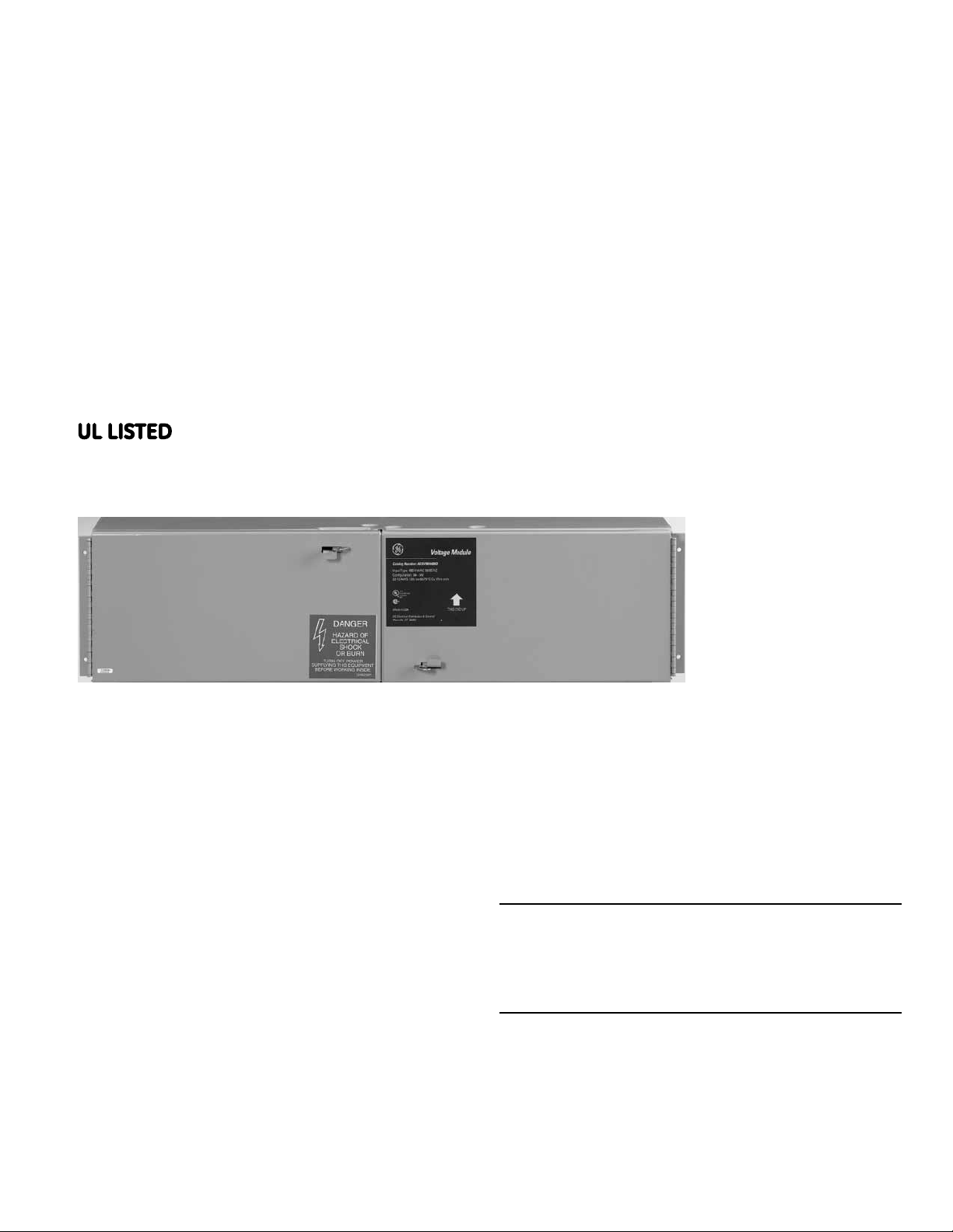
Overview
The General Electric Voltage Module is used to provide
+24Vdc Control Power to Spectra
Case Circuit Breakers with microEntelliGuard
MicroVersaTrip
Cable System. The Module also provides voltagesensing signals to Spectra
Breakers with microEntelliGuard
PM Trip Units on the same UL Listed Circuit Breaker
Accessory Distribution Cable System. The Voltage
Module is rated 24 watts (+24Vdc @ 1.0 Amp) and
has the maximum capacity to power a Distribution
Cable System consisting of 20 Spectra
Case Circuit Breakers with microEntelliGuard
MicroVersaTrip
system cable length of 40 feet. The Voltage Module is
designed to operate in temperature between 0°C and
70°C.
®
PM/Plus Trip Units via the Distribution
®
®
PM/Plus Trip Units with a maximum
®
RMS Molded-
RMS Molded-Case Circuit
TM
or MicroVersaTrip®
TM
,
®
RMS Molded-
TM
or
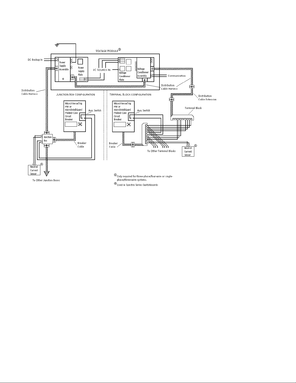
Figure 1 shows how the Voltage Module is used in a
typical MicroVersaTrip
the Voltage Module is used in a typical MicroVersaTrip
Plus system. The microEntelliGuard
support either configuration.
WARNING: Danger of electrical shock or injury. Turn
OFF power ahead of the switchboard before working
inside the equipment. Do not remove or install any circuit
protective devices, or any other component until the
power is turned OFF.
®
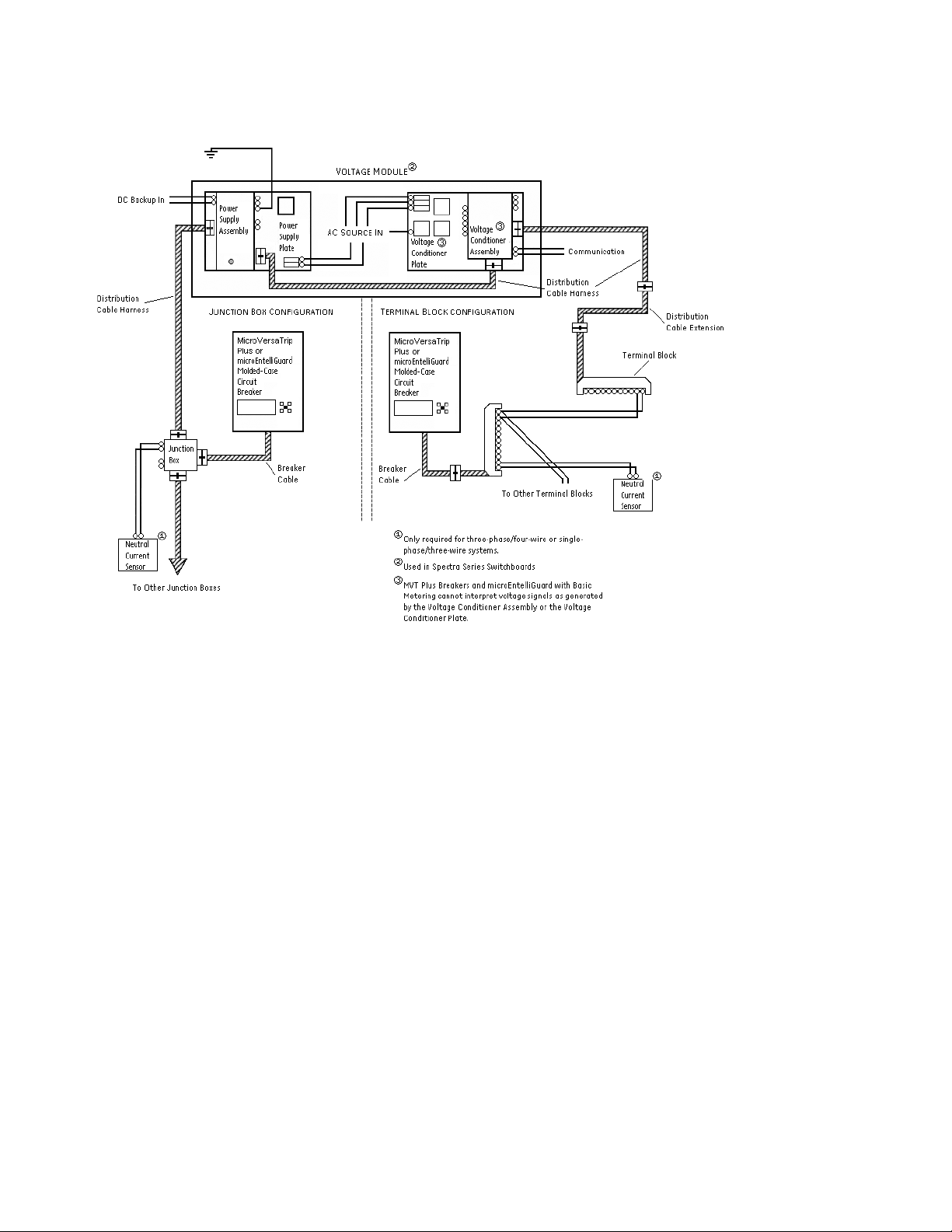
PM system. Figure 2 shows how
TM
Trip Unit can
®
Page 2
GEH-6250 Installation Instructions
Figure 1. Typical microEntelliGuardTM or MicroVersaTrip® PM Trip Unit System detailing the Voltage Module.
Page 3
GEH-6250 Installation Instructions
Figure 2. Typical microEntelliGuardTM or MicroVersaTrip® Plus Trip Unit System detailing the Voltage Module.
Page 4
GEH-6250 Installation Instructions
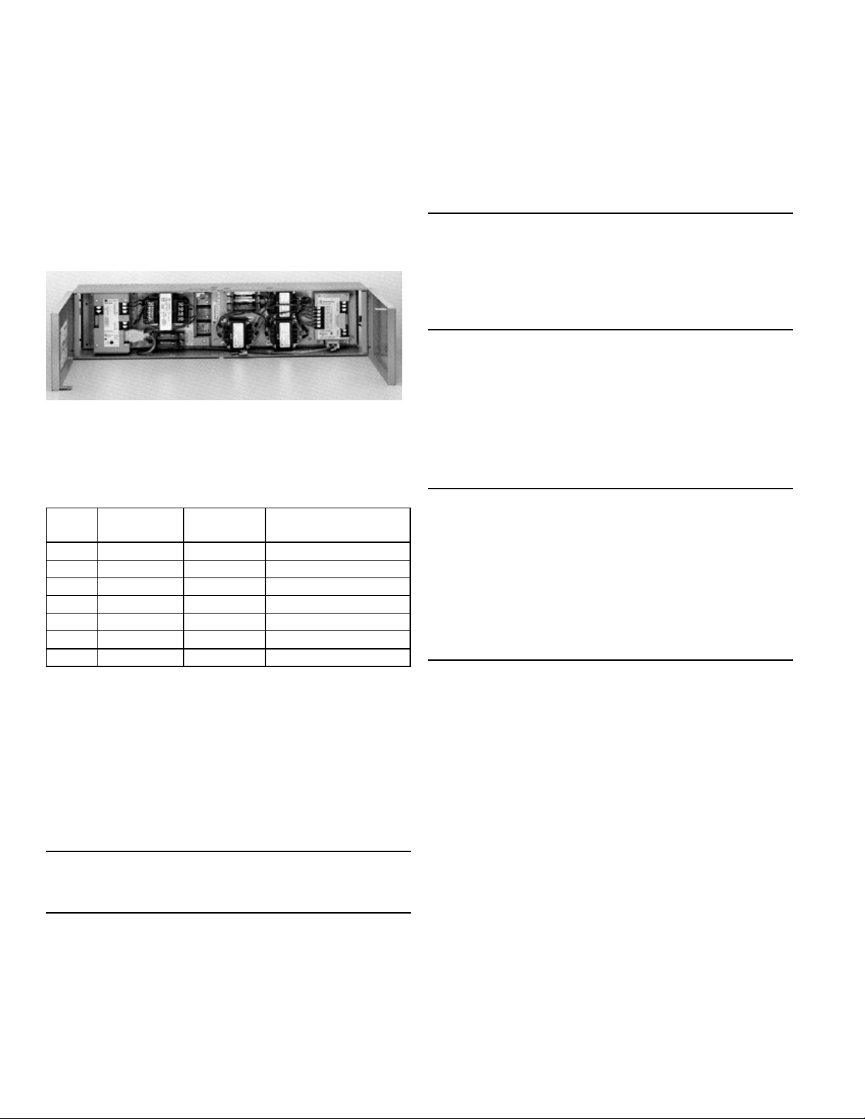
The Voltage Module contains both a Power Supply
Plate and a Voltage Conditioner Assembly as integral
components. The module also includes fuse protection
for the AC source input terminals (see Figure 3). The
Voltage Module is available in seven ratings. Table 1
contains a listing of all GE Voltage Modules. All units are
rated 60 Hz.
Figure 3. Interior view of the Voltage Module (left side Power
Supply Plate, right side Voltage Conditioner Plate)
Table 1. GE Voltage Modules
Voltage
Rating
120Vac 3f4W – Wye ADSVMA120Y Phase to Neutral potential
208Vac 3f4W – Wye ADSVMA208Y Phase to Phase potential
240Vac 3f3W – Delta ADSVMA240D Phase to Phase potential
277Vac 3f4W – Wye ADSVMA277Y Phase to Neutral potential
480Vac 3f4W – Wye ADSVMA480Y Phase to Phase potential
480Vac 3f3W – Delta ADSVMA480D Phase to Phase potential
600Vac 3f3W – Delta ADSVMA600D Phase to Phase potential
System
Configuration
Catalog
Number
Sensing Connection
EntelliGuard™ TU or a MicroVersaTrip® PM Trip Unit. (Do
®
not connect this voltage signal to a Spectra
Trip Unit.
The voltage signal structure is different between the
MCCB and ACB/ICCB Trip Unit platforms).
CAUTION: The voltage-sensing signal structure for
®
MicroVersaTrip
PM and EntelliGuard™ TU Trip Units
used in Air Circuit/Insulated Case Breakers is different
than the voltage-sensing signal structure used on
®
Spectra
RMS Breakers with MicroVersaTrip® PM or
microEntelliGuard™ Trip Units.
Additional 24Vdc output connections are supplied for
applications where +24Vdc control power is required
independent of the Distribution Cable System (i.e.
feeding Air Circuit Breakers and/or Insulated Case
®
Breakers with a MicroVersaTrip
PM/Plus Trip Units).
NOTE: THE VOLTAGE MODULE IS SIZED FOR A MAXIMUM
OF 20 BREAKERS. Use of the Voltage Module to provide
voltage-sensing signals and/or +24Vdc control power
to a main Air Circuit Breaker or a main Insulated Case
®
Breaker with a MicroVersaTrip
Trip Unit reduces the total quantity of 20 Spectra
Molded-Case Circuit Breakers with microEntelliGuard
®
or MicroVersaTrip
PM/Plus Trip Units by one. The overall
or EntelliGuardTM TU
®
RMS
TM
maximum cabling length of the system remains 40 feet.
A communications connection is provided for
applications where data is transmitted to an external
intelligent device (See Table 2). The distribution cable
system is used to interconnect the voltage signal on
®
the Voltage Conditioner Plate and the Spectra
RMS
Molded-Case Circuit Breakers.
CAUTION: The microEntelliGuard™ trip unit system
uses modbus communications and should never be
connected to a Commnet bus
An additional voltage output connection is available for
applications where a voltage signal is needed on an Air
Circuit Breaker or Insulated Case Circuit Breaker with an
Supplemental 24Vdc input terminals are provided
for systems that have access to an external +24Vdc
power supply. If this supplemental input is connected,
the Voltage Module will continue to pass the control
power to breakers and accessories connected to the
Distribution Cable System if the primary AC power is
lost or drops below the minimum requirement. This
backup input must meet ANSI C37.90.1 for oscillatory
and fast transient surges or damage to the Voltage
Module may result (the Voltage Module provides this
protection for the primary AC input). By plugging the
Voltage Module into the Distribution Cable System,
you create system wide signals that are available to
®
all Spectra
microEntelliGuard
RMS Molded-Case Circuit Breakers with
TM
or MicroVersaTrip® PM/Plus Trip
Units connected to the system; a list of available signals
appears in Table 2.
Page 5
GEH-6250 Installation Instructions
Table 2. Signals available on the Distribution Cable System by
connection of the Voltage Module.
Spectra® RMS Breaker
with MicroVersaTrip
PM Trip Unit
control power (+24vdc)
control power
(common)
system
communications
(comm. +)
system
communications
(comm. -)
voltage 1 (defined as
potential between Af &
N or between Af & Cf)
voltage 2 (defined as
potential between Bf &
N or between Cf & Bf)
voltage 3 (defined as
potential between Cf &
N or between Bf & Af)
®
Spectra
Breaker with
MicroVersaTrip
Plus Trip Unit
control power
(+24vdc)
control power
(common)
®
RMS
Spectra
Breaker with
®
microEntelliGuard
Trip Unit
control power (+24vdc)
control power
(common)
system
communications
(comm. +)
system
communications
(comm. -)
voltage 1 (defined as
potential between Af &
N or between Af & Cf)
voltage 2 (defined as
potential between Bf &
N or between Cf & Bf)
voltage 3 (defined as
potential between Cf &
N or between Bf & Af)
®
RMS
TM
The Voltage Module contains eight connection points.
Refer to Figures 5A and 5B or 6A and 6B for connection
details and location information. The following is a
detailed list of the Voltage Module connection points:
• “To Distribution Cable” (2x)
– 12-pin plug connectors that mate with the 12-pin
receptacle of a Distribution Cable Harness (catalog
number SDCHA11, SDCHA30 or SDCHA60). If the
®
Voltage Module is factory installed in a Spectra
Series Switchboard these connections are factory
wired to Distribution Cable Junction Boxes (catalog
number SDCJBB).
• “Input”
– Three-screw terminal block on the Power Supply
assembly. Use the one-terminal “GND” screw for
connection of the ground. If the Voltage Module is
®
factory installed in a Spectra
Series Switchboard,
this connection is wired to the switchboard
equipment ground (the other two-terminal screws
are pre-wired to the load side of the Power Supply
Plate fuse block).
• “Communications”
– Two-screw terminal block for Modbus
communications link or for Commnet link to the GE
POWER LEADER™ Network.
• “Supplemental Input 24Vdc”
– Two-screw terminal block for connection to an
external +24Vdc power supply.
• “Output to ACB/ICCB”
– Three-screw terminal block for an additional voltage
®
sensing signal output to MicroVersaTrip
™
EntelliGuard
TU Trip Units in Air Circuit Breakers
PM or
and/or Insulated Case Breakers.
• “Output to 24Vdc”
– Two-screw terminal block for an additional control
®
power output to MicroVersaTrip
or EntelliGuard™
TU Trip Units in Air Circuit Breakers and/or Insulated
Case Breakers.
• Three-phase rear pressure connector
– Provides an AC source connection for control power
and voltage sensing signals. If the Voltage Module is
®
factory installed in a Spectra
Series Switchboard,
these connections mate with the vertical bus bars in
the switchboard. For catalog number ADSVMA120Y
and ADSVMA277Y, an additional AC neutral
connection must be made at one of the potential
transformers. This connection is factory wired if the
®
Voltage Module is factory installed in a Spectra
Series Switchboard.
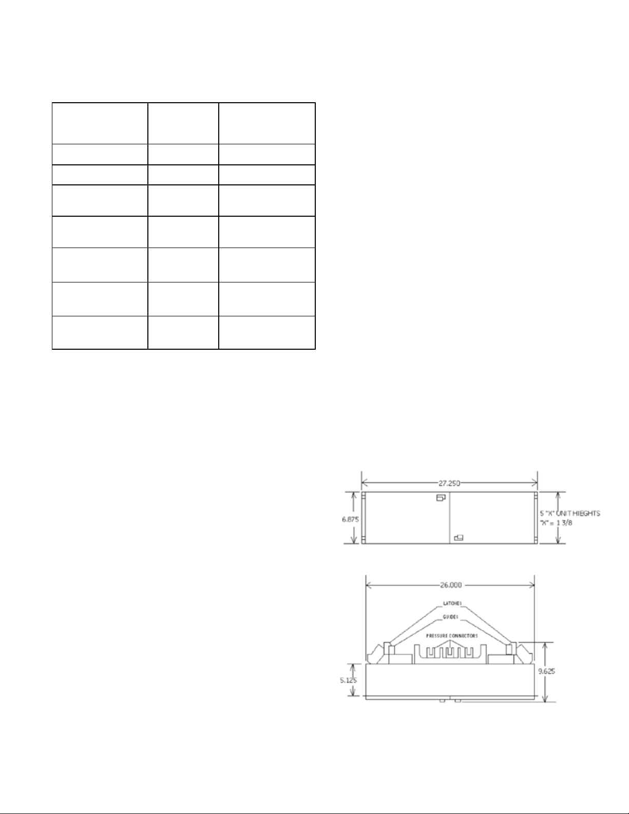
Dimensions, Weights and Wiring Diagrams
A Voltage Module dimensioned drawing is provided
in Figure 4 to assist in mounting the accessory. The
maximum unit weight is 38 pounds.
Figure 4. Dimensioned drawing of the Voltage Module
(dimensions shown in inches).
Page 6

GEH-6250 Installation Instructions
Figures 5A and 5B contain point-to-point wiring diagrams for a Voltage Module as it integrates into a typical
®
microEntelliGuard
or MicroVersaTrip™ PM Trip Unit System.
Figure 5A. Wiring Connections to the Voltage Module (left side) for a typical microEntelliGuardTM or MicroVersaTrip® PM System.
Page 7

GEH-6250 Installation Instructions
Figure5B. Wiring connections to the Voltage Module (right side) for a typical microEntelliGuardTM or MicroVersaTrip® PM System
Page 8

GEH-6250 Installation Instructions
Figures 6A and 6B contain point-to-point wiring diagrams for a Voltage Module as it integrates into a typical
®
MicroVersaTrip
Plus or microEntelliGuard™ with Basic Metering Trip Unit System.
Figure 6A. Wiring connections to the Voltage Module (left side) for a typical microEntelliGuardTM or MicroVersaTrip® Plus System.
Page 9

GEH-6250 Installation Instructions
Figure 6B. Wiring connections to the Voltage Module (Right side) For a typical microEntelliGuardTM or MicroVersaTrip® Plus System.
Page 10

GEH-6250 Installation Instructions
Installation and Connections
Prior to installing the Voltage Module confirm that the
module matches the voltage and system requirements
(refer back to Table 1). Also turn OFF power ahead of the
switchboard before proceeding with these instructions.
Step 1.
®
To install the Voltage Module into a Spectra
Series
Switchboard, first loosen the rail latch screws (A) and
retract latches (B) on both ends of the module as shown
in Figure 7.
Step 3. Finally push inward until the Voltage Module
pressure connectors are fully engaged (plugged) into
the interior bus bars. Release the latches. The latches
will automatically lock into the interior rail when the
module is fully engaged and installed. Tighten the
rail latch screw to bolt and lock the Voltage Module
in Module pressure connectors are fully engaged
(plugged) into place as shown in Figure 9.
Figure 9. Locking the Voltage Module in place.
Figure 7. Retracting the rail latches of a Voltage Module.
Step 2.
Then line up the guides on both ends of the Voltage
®
Module to notches in the Spectra
Series Switchboard
interior vertical rails (C) as shown in Figure 8.
Figure 8. Aligning the Voltage Module.
Once the Voltage Module is locked into place in the
switchboard, wiring to the Voltage Module interior
points should be made.
The screw terminals on the Voltage Module are labeled
by function for clarity (refer back to Figures 5A and 5B
or 6A and 6B for location information). The terminal
strip pockets on all terminals will accommodate a
spade lug or ring terminal with a tongue width up to
0.320 inches. The terminal screw size is 10-32. To make
the connections, attach an appropriate spade lug or
ring terminal to the wire, then slip the fastener beneath
the terminal screw and tighten.
The Voltage Module also contains two 12-pin plug
connectors. The connectors are keyed so they
cannot be inserted incorrectly into a mating 12-pin
receptacle connector. To connect to the Voltage
Module plugs, align the receptacle interlock connector
of a Distribution Cable Harness with the plug hook
connector of the Voltage Module. Insert the receptacle
until the interlock and hook catch (see Figure 10). To
disconnect from the Voltage Module, press down at the
rear of the receptacle interlock until the interlock clears
the plug hook and withdraw the receptacle interlock
(see Figure 11).
Page 11

GEH-6250 Installation Instructions
Figure 10. Side view of receptacle-plug insertion into the
Voltage Module.
Figure 11. Side view of receptacle-plug removal from the
Voltage Module.
screw terminals on the breaker. If the Air Circuit Breaker
TM
or Insulated Case Breaker has an EntelliGuard
®
MicroVersaTrip
PM Trip Unit then you must also wire
TU or
the “OUTPUT TO ACB/ICCB -VI, V2, V3” three-screw
terminal block to the appropriate voltage sensing screw
terminals on the breaker.
These last connections are necessary only when
the Voltage Module is being connected to a +24Vdc
supplemental power supply and/or a communications
network; For supplemental control power attach the
+24Vdc and 24Vdc common wires from the external
power supply to the “SUPP. INPUT 24Vdc” twoscrew terminal block. For communications network
connection, attach the black (-) and clear (+) wires of
the network bus to the “Communications” two-screw
terminal block.
®
Note: MicroVersaTrip
PM and microEntelliGuard™
Trip Units communicate via different communication
networks; microEntelliGuardTM uses Modbus and
®
MicroVersaTrip
PM uses Commnet. NEVER connect a
microEntelliGuard™ Trip Unit to a Commnet bus.
Step 4.
IMPORTANT: The following connections are mandatory
and MUST be made for all installations.
First, wire the 1-terminal “GND” screw on the Power
Supply assembly to the switchboard ground. For
catalog numbers ADSVMA120Y and ADSVMA277Y
connect a wire from the appropriate potential
transformer terminal screw on the Voltage Conditioner
Plate to the switchboard neutral bus AND ground
the secondary neutral on one of the potential
transformers.
These additional connections are required if the
®
Spectra
Series Switchboard has Air Circuit Breakers
or Insulated Case Breakers installed; If the Air Circuit
Breaker or Insulated Case Breaker has an EntelliGuard
TM
TU, MicroVersaTrip® PM, or a MicroVersaTrip® Plus Trip
Unit, then wire the “OUTPUT TO 24Vdc” two-screw
terminal block to the appropriate +24Vdc control power
The Voltage Module is now functionally wired and
ready to receive connections to the Distribution Cable
System.
Step 5.
Spectra
®
Series Switchboards incorporate the
Distribution Cable Junction Box (Cat. Nos. SDCJBB
and SDCJBBC) in the front vertical support for each
®
Spectra
microEntelliGuard
RMS Breaker with MicroVersaTrip® PM or
TM
Trip Units. Interconnection of the
breakers (Refer back to Figures 1 and 2 for connections)
is accomplished via the Distribution Cable Harness
(Cat Nos. SDCHA11, SDCHA30, and SDCHA60) linking
the Junction Box to the Voltage Module and additional
Junction Boxes. THE OVERALL MAXIMUM CABLING
LENGTH OF THE SYSTEM IS 40 FEET. Distance includes
®
the Voltage Module and ALL breakers (Spectra
Molded-Case Circuit Breakers with microEntelliGuard
®
or MicroVersaTrip
PM/Plus Trip Units, Air Circuit
RMS
TM
Breakers and Insulated Case Breakers with
TM
EntelliGuard
TU or MicroVersaTrip® PM/Plus Trip Units).
Page 12

GEH-6250 Installation Instructions
Step 6.
®
After a Spectra
microEntelliGuard
Unit is mounted on a Spectra
RMS Molded-Case Circuit Breaker with
TM
or MicroVersaTrip® PM/Plus Trip
®
Series Circuit Breaker
Module, the breaker/ mounting module assembly
®
can be installed in the Spectra
Series Switchboard.
If the breaker has a breaker cable with a 12-pin
receptacle connector, plug the breaker receptacle into
the “BREAKER” 12-pin plug connector of the nearest
Distribution Cable Junction Box.
Step 7.
®
Spectra
microEntelliGuard
RMS Molded-Case Circuit Breakers with
TM
or MicroVersaTrip® PM Trip Units
require one additional step. You MUST install an
TM
auxiliary switch (microEntelliGuard
Trip Units require
an auxiliary switch with gold plated contacts) in the
right accessory pouch of the breaker and route the
red and white wires of the switch to the “AUX SWITCH”
two-screw terminal block of the junction box. The
installation of this auxiliary switch will also require that
an IX filler plate (catalog number APPIW) be installed
®
between every Spectra
Breaker with microEntelliGuard
RMS Molded-Case Circuit
TM
or MicroVersaTrip® PM
Trip Unit.
Another use of the junction box (independent of the
Distribution Cable System) is the connection of the
®
neutral current sensor to any Spectra
Case Circuit Breaker with a microEntelliGuard
®
MicroVersaTrip
PM or a MicroVersaTrip® Plus Trip Unit
RMS Molded-
TM
,
that has the equipment ground fault option. 3Ø/3W
systems need no connection in order to function
properly. Wire the black and white wires of the neutral
current sensor to the “NEUTRAL CURRENT SENSOR”
two-screw terminal block on the junction box.
Figure 12 shows a completely wired installation of a
®
Spectra
MicroVersaTrip
RMS Molded-Case Circuit Breaker with a
®
PM Trip Unit detailing an installed
Voltage Module (D), mounted Junction Box (E),
connected Distribution Cable Harness (F), breaker
connection (G), wired auxiliary switch leads (H), and
connected current sensor wires (I).
Figure 12. Voltage Module, Spectra® RMS Molded-Case Circuit
Breakers with MicroVersaTrip
Cable Junction Boxes installed in a Spectra
®
PM Trip Units and Distribution
®
Series Switchboard.
Step 8.
Filler plates (J) are included with the Voltage Module to
assure a dead front and install the front plate (K) to the
supports of the 1X filler plate as shown on Figure 13.
Page 13

GEH-6250 Installation Instructions
Figure 13. Voltage Module installed in the Spectra® Series
Switchboard.
Parts and Options
The only user-serviceable components or parts on
the Voltage Module are the fuses in the AC INPUT fuse
blocks. The fuses listed in the Table 4 are recommended
as Replacements for use with the voltage Module.
Failure to use the proper type of fuses can result in the
damage to the Voltage Module. Five fuses per Voltage
Module are required.
Table 4. Recommended Replacement Fuses for use with the
Voltage Module
Ampere
Rating
2 amp Gould-Shawmut ATMR 2
Catalog
Manufacturer
Number Comments
Class CC current
limiting fuse
Additional Information
Refer to these other user’s manuals for more details·:
®
GEH-5934 MicroVersaTrip
PM Trip Units in Spectra
Plus and MicroVersaTrip®
®
RMS Molded-
Case Circuit Breakers
®
GEH-700 Spectra
G Breaker w/
microEntelliGuard™ Trip Unit
®
GEH-701 Spectra
K Breaker w/
microEntelliGuard™ Trip Unit
GEH-702 microEntelliGuard™ Trip Unit Users Manual
DEH-41318 Universal Rating Plug
GEH-6251 Power Supply Plate
GEH-6252 Voltage Conditioner Plate
GEH-6253 Power Supply Assembly
GEH-6254 Voltage Conditioner Assembly
GEH-703 MET Battery Pack Adapter
GEH-704 MET Advanced Distribution Cable
Junction Box
DEH-006 Distribution Cable Junction Box
GEH-705 MET Distribution Cable Extension (20-pin)
GEH-6256 Distribution Cable Extension (12-pin)
GEH-6255 Distribution Cable Harness (12-pin)
GEH-706 MET Distribution Cable Terminal Blocks
(11 point & 22 point)
GEH-6257 Distribution Cable Terminal Block (11 point)
GEH-6491 POWER LEADER™ Modbus Concentrator
GEH-6502 POWER LEADER™ PMCS 5.0 Network
Architecture Guide
GEH-707 MET Sealable Cover kits
DEH-4568 GTU digital test kit (GTUTK20)
GEH-5551 Shunt Trip and UVR instructions
GEH-5593 Aux switch and bell alarm
GEK-64467 TIM-1 Zone Selective Interlock Module
Page 14

GEH-6250 Installation Instructions
Notes
Page 15

GEH-6250 Installation Instructions
Notes
Page 16

Spectra and MicroVersaTrip are registered trademarks and EntelliGuard and
microEntelliGuard are trademarks of the General Electric Company.
These instructions do not cover all details or variations in equipment nor do they
provide for every possible contingency that may be met in connection with installation,
operation, or maintenance. Should further information be desired or should particular
problems arise that are not covered sufficiently for the purchaser’s purposes, the
matter should be referred to the GE Company.
GE Energy
41 Woodford Avenue, Plainville, CT 06062
www.geelectrical.com
© 2011 General Electric Company
imagination at work
GEH-6250 Rev. 4 (11/11 M45)
 Loading...